#esp 32 datasheet
Video
youtube
IoT Web based Smart Shopping🛒Trolley with ESP32-CAM QR Code Mobile📱Cart Application | iot based smart shopping cart using rfid and nodemcu | smart trolley using barcode scanner | smart car parking system using arduino literature review | rfid based car parking system using arduino and vb.net | smart shopping cart | Trolley for malls near me | Foldable Trolley for Shopping | Grocery Trolley with Wheels | Supermarket Trolley manufacturers | Shopping Trolley Bag | Mall Trolley price | IOT BASED SMART SHOPPING TROLLEY | IOT Based Smart Shopping Trolley for Mall.***********************************************************If You Want To Purchase the Full Working Project KITMail Us: [email protected] Name Along With You-Tube Video LinkWe are Located at Telangana, Hyderabad, Boduppal. Project Changes also Made according to Student Requirementshttp://svsembedded.com/ https://www.svskits.in/ http://svsembedded.in/ http://www.svskit.com/M1: 91 9491535690 M2: 91 7842358459 We Will Send Working Model Project KIT through DTDC / DHL / Blue Dart / First Flight Courier ServiceWe Will Provide Project Soft Data through Google Drive1. Project Abstract / Synopsis 2. Project Related Datasheets of Each Component3. Project Sample Report / Documentation4. Project Kit Circuit / Schematic Diagram 5. Project Kit Working Software Code6. Project Related Software Compilers7. Project Related Sample PPT’s8. Project Kit Photos9. Project Kit Working Video linksLatest Projects with Year Wise YouTube video Links157 Projects https://svsembedded.com/ieee_2022.php135 Projects https://svsembedded.com/ieee_2021.php 151 Projects https://svsembedded.com/ieee_2020.php103 Projects https://svsembedded.com/ieee_2019.php61 Projects https://svsembedded.com/ieee_2018.php171 Projects https://svsembedded.com/ieee_2017.php170 Projects https://svsembedded.com/ieee_2016.php67 Projects https://svsembedded.com/ieee_2015.php55 Projects https://svsembedded.com/ieee_2014.php43 Projects https://svsembedded.com/ieee_2013.php1100 Projects https://www.svskit.com/2022/02/900-pr...***********************************************************1. Smart Shopping Trolley with Automated Billing using Arduino2. RFID Based Smart Shopping Cart Using Arduino | RC5223. Automated Smart Trolley with Smart Billing Arduino | RFID4. IoT based Smart Shopping Cart using RFID and NodeMCU5. RFID based Shopping trolley6. IoT based Smart Door Lock System using NodeMCU7. IOT Based Smart Attendance System Project using NodeMCU ESP82668. DIY Smart Wi-Fi Video Doorbell using ESP32 and Camera9. IoT based Fire Alarm System Project using NodeMCU ESP826610. The Internet of Things with ESP32 | webserver | IoT Design Pro11. IoT based Smart Irrigation System using Soil Moisture Sensor12. Moduino X Series - Industrial IoT module based on ESP3213. Iot Home Automation Using ESP-32 with videos (Hindi
0 notes
Text
Power Supply for Espressif Module with Battery Charger & Boost Converter
We will discuss the integration of a power supply for the ESP32 Board. Additionally, we will add a Boost Converter Circuit to enable the use of a 3.7V Lithium-Ion Battery for powering the ESP32. Since Lithium-Ion Batteries can discharge, we will integrate a Battery Charger Circuit along with a Battery Management System. Many Lithium-Ion/Lithium Polymer Batteries can only charge up to 4.2V, which is low for the ESP32 Board.
Therefore, we need to increase the battery voltage from 2.8V-3.7V to 5V. This necessitates the use of a compact Boost Converter Module build with inductors, ICs, and resistors. To facilitate battery charging and management, we will use the TP4056 Battery Charger Module. Alternatively, we can also power the circuit using a 9V/12V DC Adapter. The LM7805 Voltage Regulator IC restricts the voltage to 5V. If you are not going to use a battery for power, you can utilize the DC Power Adapter or a 9V Battery.
ESP32 Power Requirement
The ESP32 Board’s operating voltage is between 2.2V to 3.6V. But we can supply 5V from the Micro-USB port. For applying 3.3V there is already an LDO voltage regulator on the module to keep the voltage steady at 3.3V. ESP32 can be powered using Micro USB port and VIN pin (from external supply).
The power requirement of ESP32 is 600mA of that ESP32 pulls only 250mA during the RF transmissions. When it is performing boot or wifi operation it’s drawing more than 200mA current. Thus supplying power from Micro-USB Cable is not enough for ESP32 Board when we need to add multiple sensors or modules to the Board. This is because Computer USB port can provide less than 500mA of current. Check more on power requirements of ESP32 here ESP32 Datasheet.
Hardware Requirements
Following are the components required for making this ESP32 Power Supply project. You can get all the components from our Campus Component store.
ESP32 Board-ESP32 ESP-32S Development Board (ESP-WROOM-32)
Battery Charger Module-TP4056 5V,1A Battery Charging Module
Voltage Regulator IC-LM7805 5V IC
Female DC Power Jack-DCJ0202
Step-Up Boost Converter Module-3.7V to 5V Boost Converter Module
Switch-3 Pin SPDT Switch
Electrolytic Capacitor-470uF, 25V
Electrolytic Capacitor-100uF,16V
LED-5mm LED Any Color
Resistor-220 ohm
3.7V to 5V Step-Up Boost Converter Module
The above shown is the Step-Up DC-DC Boost converter module which provides 5V DC stable voltage output for various input ranges between 1.5V to 5V. This small tiny circuit boosts the voltage level and provides the amplified stabilized 5V output. This module operates at a frequency of 150KHZ. It utilizes varying amounts of current to generate a balanced output for different input ranges.
Read more about Boost Converter
1. Input 1-1.5V, output 5V 40- 100mA
2. Input 1.5-2V, output 5V 100-150mA
3. Input 2-3V, output 5V 150-380mA
4. Input more than 3V, output 5V 380-480mA.
TP4056 Battery Charger Module
The TP4056 module is designed specifically for charging rechargeable lithium batteries through the constant-current/constant-voltage (CC/CV) charging technique. Apart from ensuring the safe charging of lithium batteries, the TP4056 BMS Board incorporates essential protection mechanisms for lithium batteries. It is compatible with both USB power and adapter power supplies. Also because of its internal PMOSFET architecture and anti-reverse charging path, there is no need for external isolation diodes.
TP4056 Module Datasheet.
Power Supply for ESP32 with Battery Charger & Boost Converter
The circuit can be powered by using two methods, one with 9V/12V DC Adapter and other with 3.7V Lithium-Ion Battery.
To power the board through the DC Jack, we've added here a DCJ0202 Female Jack. Also we have added 470uF and 100uF Electrolytic Capacitors that serve to lower the DC fluctuations and eliminate voltage spikes. The LM7805 Voltage Regulator IC is capable of handling input voltages ranging from 7V to 35V, although it's advisable to stay within the 15V limit. Higher input voltages result in increase in heat dissipation thus we have to add a larger heat sink. Connecting the Voltage regulator's output to the Vin pin of the ESP32 and grounding it ensures the module can be powered using a 9V/12V DC Adapter or a 9V Battery.
Alternatively, if opting not to utilize a DC Adapter for ESP32 power, a 3.7V Lithium-Ion or Lithium Polymer Battery can be used. Utilizing the Boost Converter Module, the 3.7V is increased to 5V, operating within the 2.8V to 4.2V input range. The boosted 5V is connected to a switch, and the switch is linked to the 5V Vin pin of the ESP32. The Battery terminal is also connected to the output terminal of the TP4056 Battery Charger Module, allowing the battery to be charged using a 5V MicroUSB Data Cable.
Conclusion
Thus by including a Battery Charger and Boost Converter to power up the esp32, we can create a flexible and efficient power for the unique requirements of the ESP32 platform. Reach out to the Campus Component- an electronics parts suppliers today, if you are building a Battery charger, Boost converter and looking for electronic components such as ESP32 and other microcontrollers from trusted brands such as Mornsun, Espressif, AIT, IKSEMI other components.
0 notes
Text
MAKER Pi Pico #2 - Sensordaten auf einer SD-Card speichern
In diesem Beitrag möchte ich dir zeigen, wie du Sensordaten am MAKER Pi Pico mit dem SD-Card Adapter auf einer entsprechenden Micro SD-Card speichern kannst.
https://youtu.be/HII4YTjos3g
Im letzten Beitrag habe ich dir gezeigt wie du Sensordaten an den IoT Service ThingSpeak senden kannst, wenn du aber einmal keine WiFi Verbindung hast oder aber dein eigenes Dashboard erstellen möchtest dann kannst du mit diesem Feature deine Daten sicher zwischenspeichern.
Den MAKER Pi Pico selber, habe ich dir bereits im Beitrag Maker Pi Pico von Cytron vorgestellt.
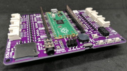
MAKER Pi Pico
Benötigte Ressourcen zum Nachbau
Möchtest du die Beispiele aus dem Beitrag nachbauen, so benötigst du folgende Ressourcen:
- MAKER Pi Pico,- Micro USB Datenkabel,
- DHT11 Sensor,
- SD-Card mit 16 GB,
- USB SD-Card Reader für den PC

MAKER Pi Pico mit Micro SD-Card
Schaltung & Aufbau
In diesem Beitrag verwende ich den DHT11 Sensor mit Grove Schnittstelle. Der DHT11 Sensor hat den Vorteil das diese zwei Werte liefert (Temperatur, rel. Luftfeuchtigkeit), jedoch den Nachteil das dieser nicht zuverlässig Werte liefert bzw. das Auslesen nicht zuverlässig funktioniert.
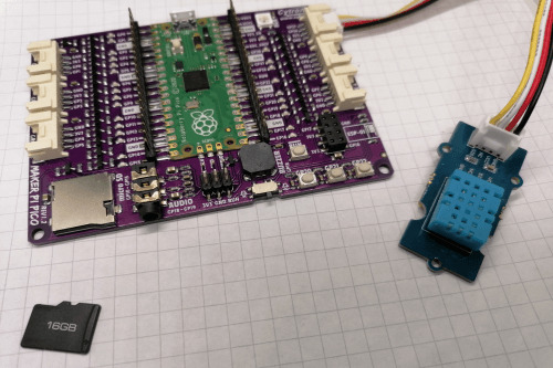
MAKER Pi Pico mit DHT11 Sensor und Micro SD-Karte
Pinout des SD-Card Adapters
Der MAKER Pi Pico hat einen SD-Card Adapter onBoard d.h. wir müssen uns nicht zusätzlich ein Modul besorgen und ggf. umständlich anschließen.
Wenn du "nur" den Raspberry Pi Pico verwenden möchtest dann gebe ich dir hier das Pinout des SD-Card Adapters.
Raspberry Pi
Pico GPIOSD ModeSPI ModeGP10CLKSCKGP11CMDSDI / MOSIGP12DAT0SDO / MISOGP13DAT1XGP14DAT2XGP15CD/DAT3CSnPinout des SD-Card Adapters am MAKER Pi Pico
Auf der Seite Maker Pi Pico Datasheet findest du weitere technische Daten zum MAKER Pi Pico.

Anschluss eines SD-Card Adapters an den Raspberry Pi Pico
In meinem Fall brauche ich nur den DHT11 Sensor anschließen und das Micro USB Kabel anschließen und bin mit dem Aufbau für diesen Beitrag fertig.
Programmieren des SD-Card Adapters am MAKER Pi Pico
Für die nachfolgenden Beispiele verwende ich das Tutorial "Write Read Data to SD Card Using Maker Pi Pico and CircuitPython" als Basis. Dieses Tutorial ist zwar in Englisch, aber durch die recht einfache Skriptsprache CircuitPython kann man den Quellcode gut lesen und verstehen.
Mounten einer SD-Card & schreiben einer Zeile in eine Textdatei
Zunächst wollen wir eine SD-Karte mounten quasi einbinden und in eine Datei eine Textzeile schreiben.
from board import *
from time import *
import busio
import sdcardio
import storage
# eine Pause von 1 Sekunde
sleep(1)
# definieren der Pins der SD-Card
spi = busio.SPI(GP10, MOSI=GP11, MISO=GP12)
cs = GP15
sd = sdcardio.SDCard(spi, cs)
# einbinden der SD Karte
vfs = storage.VfsFat(sd)
storage.mount(vfs, '/sd')
# öffnen der Datei pico.txt zum schreiben
# wenn diese Datei nicht existiert dann
# wird diese zuvor erstellt
with open("/sd/pico.txt", "w") as file:
# schreiben einer Zeile in die Datei
file.write("Hello, world!")
# schreiben eines Zeilenumbruchs
file.write("rn")
lesen von Dateien einer SD-Card
Da wir nun Daten auf die SD-Karte geschrieben haben, möchten wir diese ggf. auch auslesen.
Im Beitrag Python #10: Dateiverarbeitung habe ich dir gezeigt wie man mit Dateien & Verzeichnisse in Python arbeitet. Dieses können wir auf die leicht abgewandelte Skriptsprache CircuitPython anwenden.
from board import *
from time import *
import busio
import sdcardio
import storage
# eine Pause von 1 Sekunde
sleep(1)
# definieren der Pins der SD-Card
spi = busio.SPI(GP10, MOSI=GP11, MISO=GP12)
cs = GP15
sd = sdcardio.SDCard(spi, cs)
# einbinden der SD Karte
vfs = storage.VfsFat(sd)
storage.mount(vfs, '/sd')
# schreiben von 3 Einträgen in die Datei "greeting.txt"
# durch den Parameter "a" (a - append / anhängen )
# wird beim nächsten Start des Programmes die Datei
# NICHT überschrieben sondern 3 zusätzliche Einträge hinzugefügt
for i in range(3):
# Datei "greeting.txt" zum schreiben öffnen, die Daten werden
# an das Ende der Datei geschrieben
with open("/sd/greeting.txt", "a") as file:
# schreiben einer Zeile in die Datei
file.write("Hello World!")
# schreiben eines Zeilenumbruchs
file.write("rn")
# lesen der zuvor geschriebenen Daten von der SD Karte
with open("/sd/greeting.txt", "r") as file:
for line in file:
print(line)
Ausgabe auf der Konsole
Auf der Konsole werden nun die zuvor geschriebenen Daten angezeigt.
code.py Ausgabe:
Hello World!
Hello World!
Hello World!
Sollte das Programm jedoch mehrfach gestartet werden, so werden je Start 3 weiteren Datenzeilen hinzugefügt.
Schreiben von Sensordaten auf der SD-Karte
Möchte man Sensordaten schreiben so empfiehlt es sich diese Strukturiert zu schreiben. Man kann hierfür das JSON Format, XML oder auch das recht einfache CSV Format wählen.
Da wir lediglich die 4 Werte,
- Index,
- Zeitstempel,
- Temperatur,
- rel. Luftfeuchtigkeit
schreiben möchten, reicht für diesen Fall das CSV Format aus. (Mit den anderen beiden Formaten werde ich mich gesondert auf meinem Blog befassen.)
Was ist das CSV Format?
Das CSV Format ist wie erwähnt das einfachste Format. Die Daten werden dabei mit einem definierten Symbol getrennt in einer Zeile gespeichert. Eine Zeile endet immer mit einem Zeilenumbruch "rn".
1;2021-08-22 13:30;13;52
2;2021-08-22 13:31;15;49
Das Symbol zum Trennen von Daten innerhalb einer Zeile ist normalerweise das Semikolon. Aber es kann auch jedes andere Symbol verwendet werden. Ein Problem tritt jedoch auf wenn dieses Symbol innerhalb eines Textes in der Zeile vorkommt, dann kann ein Parser schon an seine grenzen stoßen.
Daten im CSV Format schreiben & lesen
Wollen wir zunächst ein paar Daten im CSV Format schreiben und lesen.
for i in range(3):
with open("/sd/date.txt", "a") as file:
# schreiben einer CSV Datenzeile in die Datei
file.write(str(i))
# Trenner der CSV Datei
file.write(";")
file.write("2021-08-22 13:3"+str(i))
file.write(";")
file.write(str(24))
file.write(";")
file.write(str(48))
# schreiben eines Zeilenumbruchs
file.write("rn")
# lesen der zuvor geschriebenen Daten von der SD Karte
with open("/sd/date.txt", "r") as file:
for line in file:
single_line = line.strip()
# entpacken einer Zeile in die Variablen
index, timestamp, temp, humi = single_line.split(";")
# ausgeben der Daten auf der Konsole
print("Index:", str(index))
print("Zeitstempel:", str(timestamp))
print("Temperatur:", str(temp))
print("rel. Luftfeuchtigkeit:", str(humi))
Ausgabe auf der Konsole
Auf der Konsole werden nun 3 Blöcke ausgegeben mit den zuvor gespeicherten Daten.
code.py Ausgabe:
Index: 0
Zeitstempel: 2021-08-22 13:30
Temperatur: 24
rel. Luftfeuchtigkeit: 48
Index: 1
Zeitstempel: 2021-08-22 13:31
Temperatur: 24
rel. Luftfeuchtigkeit: 48
Index: 2
Zeitstempel: 2021-08-22 13:32
Temperatur: 24
rel. Luftfeuchtigkeit: 48
Zeitstempel für die Sensordaten
Der MAKER Pi Pico verfügt über ein paar sehr nützliche Features aber eine RealTimeClock ist (bisher) nicht verbaut somit müsste man über die Pins ein solches Modul zusätzlich anschließen oder aber über einen aufgesteckten ESP01 und einer WiFi Verbindung von einem NTP Server die Zeitstempel holen.
In diesem Beispiel möchte ich einen Zeitstempel von einem kleinen PHP-Skript auf einer meiner Subdomains lesen (https://zeitstempel.draeger-it.blog/). Der Vorteil ist, dass ich das Format gleich definieren kann und somit der Code im Mu-Editor recht übersichtlich bleibt. Für diese Lösung benötigst du ein aktive WiFi Verbindung zu einem lokalen WLAN Netzwerk.
Aufbau einer WiFi Verbindung und laden des Zeitstempels von der Webseite
Wie du am MAKER Pi Pico mit dem ESP01 eine WiFi Verbindung zu deinem WLAN Netzwerk aufbaust habe ich dir im Beitrag Maker Pi Pico von Cytron bereits gezeigt.
Hier möchte ich dir lediglich das fertige Programm zum lesen eines Zeitstempels zeigen. Dieser Beitrag soll sich hautpsächlich darum drehen wie du nun die Sensordaten mit eben diesem Zeitstempel auf einer SD-Card im CSV Format speicherst.
import time
import board
import adafruit_dht
import busio
import adafruit_requests as requests
import adafruit_espatcontrol.adafruit_espatcontrol_socket as socket
from adafruit_espatcontrol import adafruit_espatcontrol
secrets = {
"ssid" : "FRITZBox7590GI24",
"password" : "abc"
}
timestamp_url = "http://zeitstempel.draeger-it.blog/"
RX = board.GP17
TX = board.GP16
uart = busio.UART(TX, RX, receiver_buffer_size=2048)
esp = adafruit_espatcontrol.ESP_ATcontrol(uart, 115200, debug=False)
requests.set_socket(socket, esp)
print("Resetting ESP module")
esp.soft_reset()
# Aufbau der WiFi Verbindung
while not esp.is_connected:
print("Connecting...")
esp.connect(secrets)
print("lesen des Zeitstempels von ", timestamp_url)
# Endlosschleife...
while True:
try:
r = requests.get(timestamp_url)
print("Zeitstempel:", r.text)
time.sleep(2)
except:
print("Fehler beim lesen des Zeitstempels von", timestamp_url)
In diesem kurzen Video zeige ich dir nun die Ausführung des oben gezeigten Programmes. (Das Passwort zu meinem WiFi-Netzwerk habe ich hier mit einem schwarzen Balken unkenntlich gemacht.)
Auf der Konsole sieht man den gelesenen Zeitstempel sowie ab und zu das nicht erfolgreich gelesen werden konnte. Ich denke das liegt hier vielmehr an einem Timeout der Verbindung, welcher zu kurz gewählt wurde. Hier kann man sich aber Abhilfe schaffen und ggf. eine kleine Schleife von 10 Durchläufen erzeugen und somit 10-mal probieren einen gültigen Zeitstempel zu laden.
Lesen eines Zeitstempels von einer Webseite.
schreiben der Sensordaten im CSV Format
Da wir nun wissen wie wir Daten auf die SD-Card schreiben und lesen, sowie einen Zeitstempel haben ist der nächste Schritt die Sensordaten auszulesen und diese Daten auf die SD-Card zu schreiben.
Damit unser Index (die erste Spalte in der CSV Datei) fortlaufend geschrieben wird, laden wir die CSV Datei beim starten des Mikrocontrollers und speichern und die Anzahl der Zeilen dieser Datei in einer Variable "index".
import time
import board
import adafruit_dht
import busio
import adafruit_requests as requests
import adafruit_espatcontrol.adafruit_espatcontrol_socket as socket
from adafruit_espatcontrol import adafruit_espatcontrol
import adafruit_dht
import sdcardio
import storage
secrets = {
"ssid" : "FRITZBox7590GI24",
"password" : "abc"
}
timestamp_url = "http://zeitstempel.draeger-it.blog/"
RX = board.GP17
TX = board.GP16
uart = busio.UART(TX, RX, receiver_buffer_size=2048)
esp = adafruit_espatcontrol.ESP_ATcontrol(uart, 115200, debug=False)
requests.set_socket(socket, esp)
# initialisieren eines DHT11 Sensors am GP27
dhtDevice = adafruit_dht.DHT11(board.GP27)
# Zähler für den Index innerhalb der CSV Datei
index = 0
# Dateiname für die Sensordaten
csv_filename = "/sd/measurements.csv"
# definieren der Pins der SD-Card
spi = busio.SPI(board.GP10, MOSI=board.GP11, MISO=board.GP12)
cs = board.GP15
sd = sdcardio.SDCard(spi, cs)
# einbinden der SD Karte
vfs = storage.VfsFat(sd)
storage.mount(vfs, '/sd')
# lesen der Sensorwerte des DHT Sensors
def read_dht_values():
result = {}
# Schleife von 0 bis 9
for i in range(9):
try:
# lesen der Sensorwerte
result = dhtDevice.temperature
result = dhtDevice.humidity
# Wenn die Temperatur ODER die rel. Luftfeuchtigkeit nicht vom Typ None ist dann,
# soll die aeussere Schleife verlassen werden.
if(result is not None or result is not None):
break;
else:
# Wenn die Daten nicht gelesen werden konnten, dann eine kleine
# Pause von 2 Sekunden einlegen.
time.sleep(2)
except RuntimeError as error:
print(error.args)
except Exception as error:
# Im Fall eines Schwerwiegenden Fehlers, so wird das Programm beendet.
dhtDevice.exit()
raise error
return result
def setup():
# Zugriff auf die Globale Variable "index"
global index
print("Setup")
# Reset des ESP01 Modules
esp.soft_reset()
# Aufbau der WiFi Verbindung
while not esp.is_connected:
print("Verbindung zu", secrets,"wird aufgebaut...")
esp.connect(secrets)
try:
index = sum(1 for line in open(csv_filename))
print("Datei", csv_filename,"enthaelt", str(index), "Zeilen")
except:
print("Datei wurde nicht gefunden.")
index = 0
# lesen des Zeitstempels von der Webseite
def read_timestamp():
timestamp = "-undefined-"
for i in range(10):
try:
r = requests.get(timestamp_url)
timestamp = r.text
# Wenn der Code bis hier funktioniert hat,
# dann kann die aeussere Schleife verlassen werden.
break;
except:
pass
time.sleep(1)
return timestamp
def loop():
global index
# lesen des Zeitstempels
timestamp = read_timestamp()
# lesen der Sensordaten
dht_values = read_dht_values()
# incrementieren des Indexes
index = index + 1
# Aufbau der CSV Datenzeile
csv_line = str(index) + ";" + timestamp + ";" + str(dht_values) + ";" + str(dht_values)
# Ausgeben der CSV Datenzeile auf der Komandozeile
print(csv_line)
# schreiben der CSV Datenzeile in die Datei
with open(csv_filename, "a") as file:
file.write(csv_line)
# hinzufügen eines Zeilenumbruchs am Zeilenende
file.write("rn")
# einmaliges Ausführen der Funktion "setup"
setup()
# Endlosschleife, welche die Funktion "loop" ausführt
while True:
loop()
# eine Pause von 1 Sekunde
time.sleep(1)
Video - schreiben der DHT11 Sensorwerte in eine CSV Datei auf der SD-Karte
Read the full article
0 notes
Text
Getting the ESP8266 Code Ready for C
Espressif chips are the sexy mcu’s these days. If you’re reading this, it’s more likely because you’re already familiar with their with what they’ve got to offer. They made their first splash - and I mean like the bombest cannonball you’ve ever seen - with the esp8266 which explorers spent some good time opening the SDK and even going so far as decapping and tracing the silicon. The chip came as an oddly shaped module with 8 pins (the ESP8266-01) then exploded into a bunch of others.

I’m here to convince you to get one if you haven’t and experiment with me because there’s a world of possibility with these. If qualitative statements don’t do it for ya, then check out these specs mostly from its wikipedia entry:
32-bit CPU (Tensilica Xtensa L106 operating at 80MHz
64KiB of instruction RAM and 96KiB of data RAM
802.11 b/g/n wifi with WPA/WPA2, WEP, and open security
2 GPIOs exposed to us (their MUXed functions aren’t great-GPIO 0 is muxed to SPI chip select and GPIO 2 is muxed to I2C SDA... ^^; buuut...)
Each GPIO can be configured for pull-up, can trigger interrupts, be configured as open drain or push-pull. Reportedly (from the datasheet), we can also do PWM but it says in another breath that it is “software programmable” which I take to mean DIY.
500kB or 1MB external SPI flash on the module (not on the SoC)
Afraid you’re going to be spending too much to get all that? YOU CAN GET 4 FOR $14.00 SO NO EXCUSES!
Of course not all of the pins are exposed so that stinks and means we don’t get all of the functionality but we’ll see what we can do with what we’ve got and maybe I’ll do another blog entry if that’s what we’d like to do.
Anyway, I love these and think you should too. I wanted to share how to get as close to main() as possible, and how to make your own tiny programming jig so....let’s GO!
Hardware
Can’t start the software without a little hardware! We need to make a quick programming jig to move between “serial programming” and “run” mode.
I used parts-box parts but you can get similar parts from almost anywhere. Just in case, here’s an ingredients list:
3.3v FTDI cable/module
ESP8266-01
Push button switch (for the reset line which is active low. You’ll see I used a mouse button for some reason but if you use a push button, you’ll need a pull up resistor)
A latched push button (for power but I used another mouse button)
DPST/DPDT switch
Headers (both female and male)
Some perf board
Here are the pin configs for serial programming:

and so this is the schematic we’re after:

Again, I only had the parts I had so here’s the schematic with what I had:

And here’s a quick map of how the perfboard is laid out:

(The boxes and blue lines represent top-layer components and wires, the red lines represent solder mazes)

(Here’s the back side so you can basically put the parts in as in the first photo and solder the traces on the back like this photo)
When all is said and done, you end up with this:

Easy as pie and hardware part done!
Software
Alright, so next up let’s get the toolchain setup, upload the blinky code, modify, and upload again so we feel good and ready to move onto projects. I chose open-esp-sdk purely because others really liked it.
This process is pretty typical but here’s the idea:
Install Dependencies (apt-get) -> Clone the Repository (git) -> Build the Project (make) -> Globalize the Tools (assigning to a global)
Then it’s time to build the example and load it up on the ESP.
Build Blinky (make) -> Power Cycle the device in program mode -> Load the new binary to the board (esptool.py) -> drink beer in celebration
Setting up the Environment
Install the Dependencies - download and install all the programs that will help you build the environment, build the esp binaries and use the upload tools
sudo apt-get install make unrar-free autoconf automake libtool gcc g++ gperf flex \ bison texinfo gawk ncurses-dev libexpat-dev python-dev python python-serial \ sed git unzip bash help2man wget bzip2 libtool-bin
Clone the repository - for those who are new to git (many at my company were when they came aboard, obviously me included) all this is is just copying a project that someone has posted to git down to your computer. Make sure you go to the directory where you want your project to reside and type:
`git clone --recursive https://github.com/pfalcon/esp-open-sdk.git`
Build the Environment - When it’s done, cd into the esp-open-sdk directory and make the project
cd esp-open-sdkmake STANDALONE=y
The “STANDALONE=y” ensures you get the xtensa toolchain and the esp SDK.
Depending on your hardware this may take a while. Just for shits and giggles I installed it on my Crubuntu laptop which took an hour (to be fair I was watching netflix on the Chrome side). If it goes off without a hitch, it will report
Espressif ESP8266 SDK is installed, its libraries and headers are merged with the toolchain
Pitfalls
I’ve encountered two errors when I tried this though - one was when I followed the github instructions and didn’t try to install libtools-bin (since it said you may not require it). For safety, I just put it in my apt-get command above.
The other was because I had played around a bunch on my computer and had the LD_LIBRARY_PATH variable set to which it complained
[ERROR] Don't set LD_LIBRARY_PATH. It screws up the build.
If that happens, make sure you clear your LD_LIBRARY_PATH environmental variable with
unset LD_LIBRARY_PATH
and try again.
Globalize the Tools - We’ll want to make it so that we can access the xtensa gcc toolchain (which we’ll use to compile link and convert our sourcecode to ELF) and the esptools (which we’ll use to convert to a binary and write to flash locations on the chip over serial) everywhere. To make that happen, we need to add the path to xtensa-lx106-elf-gcc and esptool.py to the ~/.bashrc - the file that loads every time we load a terminal session.
There should have been a line above the success message that says
Xtensa toolchain is built, to use it:
export PATH=[your_path_to_esp_open_sdk]/esp-open-sdk/xtensa-lx106-elf/bin:$PATH
Go ahead and do that - type:
export PATH=[your_path_to_esp_open_sdk]/esp-open-sdk/ xtensa-lx106-elf/bin:$PATH
But let’s also add it to our ~/.bashrc which controls what happens when we open a new terminal:
echo “export PATH=[your_path_to_esp_open_sdk]/esp-open-sdk/ xtensa-lx106-elf/bin:$PATH” >> ~/.bashrc
and then we’re good! To test if that worked, cd to the esp-open-sdk directory and then do
cd examples/blinky
and type
make
If that went through well (i.e. it didn’t throw any complaints to you), you’ve properly configured your environmental path variable. Now remove the blinky binaries (make seems to make different binary locations than those used in make flash and make clean)
rm -f blinky blinky.o blinky-0x00000.bin blinky-0x10000.bin
Testing with blinky.c
Our next goal is to run blinky on the board.
Test the Serial Port
First let’s make sure we have access to the serial port so we can program the device. Connect your FTDI programmer to your USB port and type
dmesg | grep FTDI
It should list a line like this to tell you which /dev the FTDI connected to like
usb 1-2: FTDI USB Serial Device converter now attached to ttyUSB0
Next, send something like (where ttyUSB0 is the device you got)
echo -ne “\r\n” > /dev/ttyUSB0
If you just get another prompt pop up immediately after, you shouldn’t have anything to worry about and can move to the next section. If you get the Permission Denied message, you need to add yourself to the same group as your FTDI port. Let’s find out which group we need to be a part of. Type:
ls -l /dev/ttyUSB0
and you should get something like:
crw-rw---- 1 root serial 188, 0 Jun 19 02:52 /dev/ttyUSB0
Many sites online just say to add to “dialout” but you see that my port is connected to the group “serial.” I can add myself to that group with:
sudo usermod -a -G serial alexmo
and then log out and log back in.
Now when you’re back in, if you retype
echo -ne “\r\n” > /dev/ttyUSB0
you shouldn’t see the permission denied message.
Build
Build with
make
You’ll see a few new files. The binaries marked blinky-0x00000.bin and blinky-0x10000.bin tell you where they should be written.
Program
Now let’s program the device with the binaries. If you see blinky-0x00000.bin and blinky-0x10000.bin, just type
esptool.py write_flash 0 blinky-0x00000.bin 0x10000 blinky-0x10000.bin
It will work on it:
esptool.py v1.2
Connecting...
Auto-detected Flash size: 4m
Running Cesanta flasher stub...
Flash params set to 0x0000
Writing 36864 @ 0x0... 36864 (100 %)
Wrote 36864 bytes at 0x0 in 3.2 seconds (91.5 kbit/s)...
Writing 196608 @ 0x10000... 196608 (100 %)
Wrote 196608 bytes at 0x10000 in 17.1 seconds (92.1 kbit/s)...
Leaving...
and then start blinking!

0 notes
Video
youtube
IoT Web based Smart Shopping🛒Trolley with ESP32-CAM QR Code Mobile📱Cart Application | IoT based Smart Shopping Cart using RFID and NodeMCU | Smart Shopping Trolley using QR Code and ESP32Cam | IoT based Smart Shopping Trolley with Mobile Cart Application | Smart Shopping Using QR Code and ESP32-CAM | IOT | AUTOMATED BILLING SYSTEM SMART TROLLEY USING ESP32 CAM MODULE WITH THE HELP OF ARDUINO UNO | Scanning QR Codes With the ESP32-CAM | qr code based examination room guidance system using esp32-cam and raspberry pi pico.***********************************************************If You Want To Purchase the Full Working Project KITMail Us: [email protected] Name Along With You-Tube Video LinkWe are Located at Telangana, Hyderabad, Boduppal. Project Changes also Made according to Student Requirementshttp://svsembedded.com/ https://www.svskits.in/ http://svsembedded.in/ http://www.svskit.com/M1: 91 9491535690 M2: 91 7842358459 We Will Send Working Model Project KIT through DTDC / DHL / Blue Dart / First Flight Courier ServiceWe Will Provide Project Soft Data through Google Drive1. Project Abstract / Synopsis 2. Project Related Datasheets of Each Component3. Project Sample Report / Documentation4. Project Kit Circuit / Schematic Diagram 5. Project Kit Working Software Code6. Project Related Software Compilers7. Project Related Sample PPT’s8. Project Kit Photos9. Project Kit Working Video linksLatest Projects with Year Wise YouTube video Links157 Projects https://svsembedded.com/ieee_2022.php135 Projects https://svsembedded.com/ieee_2021.php 151 Projects https://svsembedded.com/ieee_2020.php103 Projects https://svsembedded.com/ieee_2019.php61 Projects https://svsembedded.com/ieee_2018.php171 Projects https://svsembedded.com/ieee_2017.php170 Projects https://svsembedded.com/ieee_2016.php67 Projects https://svsembedded.com/ieee_2015.php55 Projects https://svsembedded.com/ieee_2014.php43 Projects https://svsembedded.com/ieee_2013.php1100 Projects https://www.svskit.com/2022/02/900-pr...***********************************************************1. Smart Shopping Trolley with Automated Billing using Arduino2. RFID Based Smart Shopping Cart Using Arduino | RC5223. Automated Smart Trolley with Smart Billing Arduino | RFID4. IoT based Smart Shopping Cart using RFID and NodeMCU5. RFID based Shopping trolley6. IoT based Smart Door Lock System using NodeMCU7. IOT Based Smart Attendance System Project using NodeMCU ESP82668. DIY Smart Wi-Fi Video Doorbell using ESP32 and Camera9. IoT based Fire Alarm System Project using NodeMCU ESP826610. The Internet of Things with ESP32 | webserver | IoT Design Pro11. IoT based Smart Irrigation System using Soil Moisture Sensor12. Moduino X Series - Industrial IoT module based on ESP3213. Iot Home Automation Using ESP-32 with videos (Hindi
0 notes
Photo

Buy Espressif ESP Wrover kit & development board online at affordable price from Campus Component a leading electronic component provider in India. The ESP-WROVER-KIT-VB is a variant of ESP-WROVER-KIT that comes with an ESP32-WROVER-B module by default. This board features support for an LCD and Micro SD card. The I/O pins have been broken out from the ESP32-WROVER-B for easy extension.
The board carries an advanced multi-protocol USB bridge (the FTDI FT2232HL), enabling developers to use JTAG directly to debug the ESP32 module through the USB interface. The development board makes secondary development easy and cost-effective. Module is FCC/ CE/ KCC/ IC/ TELEC/ SRRC/NCC certified. To know more about this product call on
+919767444555
or visit website
https://www.campuscomponent.com/products/espressif-esp-wrover-kit-vb-2-4-ghz-wifi-and-bt-ble-development-board/2208614000001841096
#Espressif ESP Wrover#esp32 wrover#esp32 development board#esp 32 datasheet#esp32 espressif#esp8266 wifi module#esp module
0 notes
Link
Buy Espressif ESP Wrover kit & development board online at affordable price from Campus Component a leading electronic component provider in India. The ESP-WROVER-KIT-VB is a variant of ESP-WROVER-KIT that comes with an ESP32-WROVER-B module by default. This board features support for an LCD and Micro SD card. The I/O pins have been broken out from the ESP32-WROVER-B for easy extension.
The board carries an advanced multi-protocol USB bridge (the FTDI FT2232HL), enabling developers to use JTAG directly to debug the ESP32 module through the USB interface. The development board makes secondary development easy and cost-effective. Module is FCC/ CE/ KCC/ IC/ TELEC/ SRRC/NCC certified. To know more about this product call on
+919767444555
or visit website
https://www.campuscomponent.com/products/espressif-esp-wrover-kit-vb-2-4-ghz-wifi-and-bt-ble-development-board/2208614000001841096
#Espressif ESP Wrover#esp32 wrover#esp32 development board#esp 32 datasheet#esp32 espressif#esp8266 wifi module#esp module
0 notes
Last Seen Blogs

countingoutbigtime
my prog blog

quibbling-xeno
Queer Quibblings and Serendipitous Somethings

conversionfeatures
Sin título


vol5anthology
Homestuck Vol. 5 Track Art Fan Anthology