#esp8266 wifi module
Explore tagged Tumblr posts
Visit Tumblr Blog
Explore Tumblr blogs with no restrictions, modern design and the best experience.
Last Seen Tumblr Blogs


Fun Fact
1,644 Tumblr posts in 1 second.
Text
DESCRIPTION:
NodeMCU is an IoT Module based on the ESP8266 wifi Module. NodeMCU uses Lua Scripting language and is an open-source Internet of Things (IoT) platform. This module has CH340g USB to TTL IC.
2 notes
·
View notes
Text
DIY: Easiest Standalone Deauther

Previously, I have built a standalone Deauther with an OLED display and buttons over here, but realistically, everyone is just going to use the web interface. So, I recently found an ESP8266 ESP-07 USB module that is perfect for a standalone Deauther, since it has a USB connector built-in and you can just plug it into any powerbank. This module cost me around USD3 and you can find it in AliExpress.


First, we need to download the Deauther firmware. Go to this page and download this file: esp8266_deauther_2.6.1_DSTIKE_NODEMCU_07_V2.bin
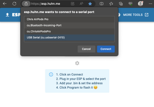
Next, set the switch on the ESP module to "PROG" and plug it into your computer's USB. Run Google Chrome or Microsoft Edge browser and go to https://esp.huhn.me. Click CONNECT and select the USB Serial item and click Connect.

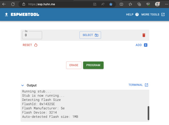
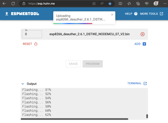
Now that it has successfully connected, click SELECT and choose the firmware file you downloaded earlier, then hit the PROGRAM button.

It should now start flashing, so just let it finish the job.
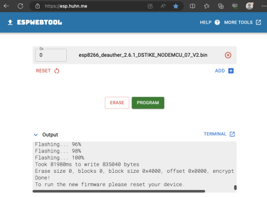
Finally, flick the switch on the ESP module from PROG to UART, and hit the reset button on the ESP module while still plugged into USB, or you can just remove it from your computer and plug it into a powerbank. On your phone/computer, just connect to the Wifi network "pwned" and use "deauther" for the password. Then open your web browser and go to http://192.168.4.1


That's it! You now have a standalone Deauther. More information about using the web interface over here. Also, realize that in most countries, there are laws against disrupting communication networks and Deauth attacks may be illegal.
4 notes
·
View notes
Text
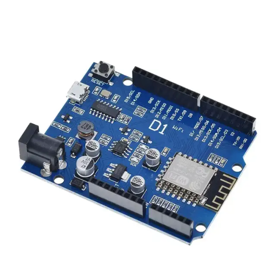
Wemos D1 Wifi Dev Board for Esp8266 IOT Module Online price is 10 units MOQ. Specification: Based on ESP-8266EX Compatible with Arduino,can be program by arduino ide. I/O Pin:11pcs Working Voltage:3.3V Input:7-24V Flash:4MB SRAM:32KB DRAM:80KB Clock Frequency:80MHz/160Mhz Network:802.11b/g/n Other development board you may interest: Interested with much more quantity,contact us to talk price.Know more about company site here. Read the full article
1 note
·
View note
Text
DIY Smart Home Energy Monitor with ESP32 and Home Assistant
Introduction
Managing energy consumption is a great way to reduce electricity costs and contribute to environmental sustainability. With the help of IoT, you can monitor energy usage in real-time, right from your smartphone. In this guide, we’ll build a Smart Home Energy Monitor using an ESP32 microcontroller, current and voltage sensors (like the ACS712 or SCT-013), and the MQTT protocol for data transmission. This data will be accessible on a mobile app via Home Assistant, allowing you to keep track of energy usage and optimize it effectively.
Project Overview
Objectives
Monitor power consumption in real-time for home appliances.
Display energy usage on a mobile app using MQTT and Home Assistant.
Analyze data over time to make informed decisions about energy usage.
Key Components
ESP32 (or ESP8266) microcontroller: For reading sensor data and connecting to Wi-Fi.
Current Sensor (SCT-013 or ACS712): For measuring current drawn by appliances.
Voltage Sensor: Optional, but adds more accuracy if you want to measure precise power usage.
MQTT Protocol: To send data to Home Assistant for real-time monitoring.
Home Assistant: A home automation platform to display and analyze data.
Part 1: Setting Up the Components
1. ESP32 or ESP8266 Microcontroller
Choose either the ESP32 or ESP8266 microcontroller. The ESP32 has more features and is preferred, but either will work.
Connect the ESP32 to your computer using a USB cable to program it.
2. Current Sensor (SCT-013 or ACS712)
SCT-013 is a non-invasive sensor that clamps around a wire to measure the AC current flowing through it.
ACS712 is a current sensor that can measure both AC and DC current but requires direct connection to the wire, so exercise caution with high voltage.
Wiring for SCT-013
Connect the SCT-013 sensor’s output to an analog input pin on the ESP32.
If you’re using SCT-013 with ESP8266, you’ll need an analog-to-digital converter (ADC) module since the ESP8266 has only one analog input pin with limited resolution.
Wiring for ACS712
Connect the VCC pin to the 3.3V or 5V pin on the ESP32.
Connect the OUT pin to an analog input pin on the ESP32.
Connect the GND pin to the ground (GND) on the ESP32.
3. Voltage Sensor (Optional)
A voltage sensor can be added to measure the actual voltage if you want to calculate power more accurately.
Connect the sensor’s VCC to the 3.3V on ESP32, GND to ground, and OUT to an analog input.
Part 2: Coding the ESP32 for Data Acquisition and Transmission
1. Install the Required Libraries
Make sure you have the following libraries installed in your Arduino IDE:
ESP32 or ESP8266 board support (depending on your microcontroller)
PubSubClient library for MQTT communication
WiFi library for connecting to your Wi-Fi network
2. Set Up the Code
Here’s the code to:
Read values from the current sensor.
Calculate power consumption (voltage x current if you have a voltage sensor, or assume constant voltage).
Publish data to an MQTT broker.
#include <WiFi.h> #include <PubSubClient.h>
// Wi-Fi and MQTT Broker Settings const char* ssid = "YOUR_SSID"; const char* password = "YOUR_PASSWORD"; const char* mqtt_server = "YOUR_MQTT_BROKER_IP";
// MQTT topics const char* topicPower = "home/energy_monitor/power";
WiFiClient espClient; PubSubClient client(espClient);
// Sensor parameters const int sensorPin = 34; // Analog pin for sensor (ESP32) const float voltageCalibration = 230.0; // Voltage in volts (modify as per your region) const float sensorCalibration = 0.185; // Calibration constant for ACS712 sensor
void setup() { Serial.begin(115200); setup_wifi(); client.setServer(mqtt_server, 1883); }
void setup_wifi() { delay(10); Serial.println("Connecting to WiFi..."); WiFi.begin(ssid, password); while (WiFi.status() != WL_CONNECTED) { delay(500);
Serial.print("."); } Serial.println("Connected to WiFi."); }
void reconnect() { while (!client.connected()) { Serial.print("Connecting to MQTT..."); if (client.connect("ESP32Client")) { Serial.println("Connected."); } else { delay(5000); } } }
void loop() { if (!client.connected()) { reconnect(); } client.loop();
// Read sensor data int rawValue = analogRead(sensorPin); float current = rawValue * sensorCalibration; // Adjust based on sensor
// Calculate power float power = voltageCalibration * current; // Simple power calculation (P=VI)
// Publish data to MQTT String powerStr = String(power); client.publish(topicPower, powerStr.c_str()); Serial.print("Power: "); Serial.println(power); delay(2000); // Send data every 2 seconds }
3. Upload Code
Connect your ESP32 to your computer.
Select the correct board and port in the Arduino IDE.
Upload the code to the ESP32.
Part 3: Setting Up Home Assistant and MQTT Broker
1. Set Up MQTT Broker
If you don’t have an MQTT broker, you can use Mosquitto on your local network or use an online MQTT service like HiveMQ.
Install Mosquitto on a Raspberry Pi or a computer running Home Assistant.
Configure Mosquitto by setting a username and password for secure access.
2. Configure Home Assistant
In Home Assistant, you’ll add the MQTT integration to receive data from the ESP32.
Go to Settings > Integrations and search for MQTT.
Enter your MQTT broker details and save the configuration.
3. Add a Sensor in Home Assistant
In your Home Assistant configuration file (configuration.yaml), add the following entry to display power data:sensor: - platform: mqtt name: "Home Power Consumption" state_topic: "home/energy_monitor/power" unit_of_measurement: "W" value_template: "{{ value | float }}"
Restart Home Assistant to apply changes.
You should now see a Home Power Consumption sensor in your Home Assistant dashboard.
Part 4: Testing and Using the Energy Monitor
Power on your ESP32 and ensure it’s connected to Wi-Fi.
Open Home Assistant, where you should see the real-time data of power consumption.
Monitor the data over time and optimize energy usage based on the data.
Conclusion
With this DIY Smart Home Energy Monitor, you can track power usage across various appliances in your home. This project introduces core IoT concepts such as data acquisition, MQTT communication, and integration with Home Assistant. You can further expand this setup by adding more sensors or even automating appliances based on usage patterns.
#Tech4bizsolutions #SmartHome #EnergyMonitoring #ESP32Projects #HomeAssistant #IoTProjects #DIYElectronics #MQTTProtocol #SmartHomeAutomation #PowerConsumption #EnergyEfficiency #ESP8266Projects #IoTDevelopment #HomeAutomationIdeas #TechDIY #SustainableLiving
0 notes
Text
Buy nodemcu esp8266 cp2102 at Affordable Price in Ainow

The ESP8266 NodeMCU CP2102 board has ESP8266 which is a highly integrated chip designed for the needs of a new connected world. It offers a complete and self-contained Wi-Fi networking solution, allowing it to either host the application or to offload all Wi-Fi networking functions from another application processor. ESP8266 has powerful onboard processing and storage capabilities that allow it to be integrated with the sensors and other application specific devices through its GPIOs with minimal development up-front and minimal loading during runtime. Its high degree of on-chip integration allows for minimal external circuitry, and the entire solution, including the front-end module, is designed to occupy minimal PCB area. The ESP8266 NodeMCU CP2102 development board – a true plug-and-play solution for inexpensive projects using WiFi. The module arrives pre-flashed with NodeMCU firmware so they’re ready to go – just install your USB driver (below). ESP-12 Lua Nodemcu WIFI Dev Board Internet Of Things board contains a full ESP8266 WiFi module with all the GPIO broken out, a full USB-serial interface, and a power supply all on the one breadboard-friendly package. This board is pre-flashed with NodeMCU a Lua-based firmware for the ESP8266 which allows easy control via a neat scripting language Lua so you’re ready to go in just a few minutes. The ESP-12 Lua Nodemcu WIFI Dev Board Internet Of Things with ESP8266 is an all-in-one microcontroller WiFi platform that is very easy to use to create projects with WiFi and IoT (Internet of Things) applications. The board is based on the highly popular ESP8266 WiFi Module chip with the ESP-12 SMD footprint. This WiFi development board already embeds in its board all the necessary components for the ESP8266 (ESP-12E) to program and upload code. It has a built-in USB to serial chip upload codes, 3.3V regulator, and logic level converter circuit so you can immediately upload codes and connect your circuits.
0 notes
Text
Grand Strategy Manifesto (16^12 article-thread ‘0x1A/?)

youtube
Broken down many times yet still unyielding in their vision quest, Nil Blackhand oversees the reality simulations & keep on fighting back against entropy, a race against time itself...
So yeah, better embody what I seek in life and make real whatever I so desire now.
Anyways, I am looking forward to these... things in whatever order & manner they may come:
Female biological sex / gender identity
Ambidextrous
ASD & lessened ADD
Shoshona (black angora housecat)
Ava (synthetic-tier android ENFP social assistance peer)
Social context
Past revision into successful university doctorate graduation as historian & GLOSS data archivist / curator
Actual group of close friends (tech lab peers) with collaborative & emotionally empathetic bonds (said group large enough to balance absences out)
Mutually inclusive, empowering & humanely understanding family
Meta-physics / philosophy community (scientific empiricism)
Magicks / witch coven (religious, esoteric & spirituality needs)
TTRPGs & arcade gaming groups
Amateur radio / hobbyist tinkerers community (technical literacy)
Political allies, peers & mutual assistance on my way to the Progressives party (Harmony, Sustainability, Progress) objectives' fulfillment
Local cooperative / commune organization (probably something like Pflaumen, GLOSS Foundation & Utalics combined)
Manifesting profound changes in global & regional politics in a insightful & constructive direction to lead the world in a brighter direction fast & well;
?
Bookstore
Physical medium preservation
Video rental shop
Public libraries
Public archives
Shopping malls
Retro-computing living museum
Superpowers & feats
Hyper-competence
Photographic memory
600 years lifecycle with insightful & constructive historical impact for the better
Chronokinesis
True Polymorph morphology & dedicated morphological rights legality (identity card)
Multilingualism (Shoshoni, French, English, German, Hungarian, Atikamekw / Cree, Innu / Huron...)
Possessions
Exclusively copyleft-libre private home lab + VLSI workshop
Copyleft libre biomods
Copyleft libre cyberware
Privacy-respecting wholly-owned home residence / domain
Privacy-respecting personal electric car (I do like it looking retro & distinct/unique but whatever fits my fancy needs is fine)
Miyoo Mini+ Plus (specifically operating OnionOS) & its accessories
BeagleboneY-AI
BeagleV-Fire
RC2014 Mini II -> Mini II CP/M Upgrade -> Backlane Pro -> SIO/2 Serial Module (for Pro Tier) -> 512k ROM 512k RAM Module + DS1302 Real Time Clock Module (for ZED Tier) -> Why Em-Ulator Sound Module + IDE Hard Drive Module + RP2040 VGA Terminal + ESP8266 Wifi + Micro SD Card Module + CH375 USB Storage + SID-Ulator Sound Module -> SC709 RCBus-80pin Backplane Kit -> MG014 Parallel Port Interface + MG011 PseudoRandomNumberGen + MG003 32k Non-Volatile RAM + MG016 Morse Receiver + MG015 Morse Transmitter + MG012 Programmable I/O + "MSX Cassette + USB" Module + "MSX Cartridge Slot Extension" + "MSX Keyboard" -> Prototype PCBs
Intersil 6100/6120 System ( SBC6120-RBC? )
Pinephone Beta Edition Convergence Package (Nimrud replacement)
TUXEDO Stellaris Slim 15 Gen 6 AMD laptop (Nineveh replacement)
TUXEDO Atlas X - Gen 1 AMD desktop workstation (Ashur replacement)
SSD upgrade for Ashur build (~4-6TB SSD)
LTO Storage
NAS RAID6 48TB capacity with double parity (4x12TB for storage proper & 2x12TB for double parity)
Apple iMac M3-Max CPU+GPU 24GB RAM MagicMouse+Trackpad & their relevant accessories (to port Asahi Linux, Haiku & more sidestream indie-r OSes towards… with full legal permission rights)
Projects
OpenPOWER Microwatt
SPARC Voyager
IBM LinuxOne Mainframe?
Sanyo 3DO TRY
SEGA Dreamcast with VMUs
TurboGrafx 16?
Atari Jaguar CD
Nuon (game console)
SEGA's SG-1000 & SC-3000?
SEGA MasterSystem?
SEGA GameGear?
Casio Loopy
Neo Geo CD?
TurboExpress
LaserActive? LaserDisc deck?
45rpm autoplay mini vinyl records player
DECmate III with dedicated disk drive unit?
R2E Micral Portal?
Sinclair QL?
Xerox Daybreak?
DEC Alpha AXP Turbochannel?
DEC Alpha latest generation PCI/e?
PDP8 peripherals (including XY plotter printer, hard-copy radio-teletypes & vector touchscreen terminal);
?
0 notes
Text
ESP8266 Wifi Module | Nodemcu ESP8266 for IoT Solution
The Internet of Things (IoT) is revolutionizing the way we interact with technology, making our lives smarter and more efficient. At the heart of this revolution is the ESP8266 WiFi module, a low-cost, powerful solution perfect for your IoT projects. Whether you're a hobbyist, a professional developer, or a business looking to integrate smart technology into your products, the ESP8266 WiFi module offers unmatched versatility and performance. Here's why you should consider buying the ESP8266 WiFi module and how the NodeMCU ESP8266 can be your gateway to a myriad of IoT solutions.
What is the ESP8266 WiFi Module?
The ESP8266 is a highly integrated chip designed for the needs of a new connected world. It offers a complete and self-contained WiFi networking solution, allowing it to either host the application or offload all WiFi networking functions from another application processor. With its low cost and high performance, the ESP8266 WiFi module has become a popular choice among IoT developers.
ESP8266 NodeMcu WiFi Development Board Features:-
It is based on ESP8266, integates GPIO, PWM, IIC, 1-Wire and ADC all in one board.
Power your developement in the fastest way combinating with NodeMCU Firmware!
USB-TTL included, plug&play
10 GPIO, every GPIO can be PWM, I2C, 1-wire
Open source IoT Platform
Easily Programmable
Low cost & Simple to Implement
WI-FI enabled
ESP8266 NodeMcu WiFi Development Board Applications:-
Home Appliances
Home Automation
Smart Plug and lights
Mesh Network
Industrial Wireless Control
Baby Monitors
IP Cameras
Sensor Networks
Wearable Electronics
Why Choose NodeMCU ESP8266 for Your IoT Projects?
Ease of Use: NodeMCU's integrated USB-to-serial interface and pre-flashed firmware allow for immediate programming and development.
Versatile Programming: You can program the NodeMCU using the Arduino IDE or NodeMCU’s native Lua scripting language, giving you flexibility in development.
Wide Community Support: As one of the most popular IoT development platforms, NodeMCU has extensive documentation and a large community, making it easier to find support and resources.
Cost-Effective: NodeMCU provides a highly cost-effective solution for IoT development, offering excellent value for money.
Rapid Prototyping: Its comprehensive feature set and ease of use make NodeMCU ideal for rapid prototyping and deployment of IoT solutions.
Conclusion
Purchase Your ESP8266 and NodeMCU ESP8266 Today!
Don't miss out on the opportunity to enhance your IoT projects with the best technology available. Purchase your ESP8266 WiFi module and NodeMCU ESP8266 development board today and join the growing community of IoT developers who are shaping the future of technology.
Innovation awaits at Campus Component, where you can buy genuine ESP8266 NodeMCU boards at competitive prices. Take the first step towards realizing your IoT dreams and explore the endless possibilities of connected devices. Order now and join the IoT revolution with Campus Component as your trusted partner.
0 notes
Text
s2emodule #serialtoethernet #ethernet #wiznet #ethernetmodule #w7500P #WIZ110SR #WIZ750SR #s2emodul #ethernetic #wiznetian #ethernetchip #arduino #esp32 esp8266 #ethernet #eth #wiznetchip #w5500 #ethernet #rs485 #modbusrtu #modbus #serialtoethernet #rs232 #canbus
0 notes
Link
#Arduino #ESP8266 #HomeAutomation
5 notes
·
View notes
Text
Visit Quazrtz Components today to buy your 5V Relay Module! 🛒 This versatile module is essential for controlling high-voltage devices with low-voltage microcontrollers. Enjoy reliable performance and easy integration into your electronic projects. Don't miss out—grab yours now and take your DIY electronics to the next level!
1 note
·
View note
Text
DIY: ESP32 Cam + ESP8266 Combo Flipper Zero Module
Here is my project for this weekend, a Flipper Zero module with both ESP32 CAM and ESP8266 D1 Mini combined. This allows me to use it for Marauder, Deauther, WiFi Scanner, Camera, Morse Flash, etc. in a single module. I did consider doing a Mayhem board with NRF24/CC1101, but I find myself rarely using them and Flipper has CC1101 built in anyway (just with shorter range).

The steps to build it is relatively simple. It just combines the two separate modules and some switches to switch between between the two. Below is a quick guide on how I build it. Note that this is not meant to be a detailed step by step tutorial. If you have some experience with building electronic projects, you should be able to follow along.
Build Steps
Start by cutting the prototype board to the required size and the header pins to the correct lengths (8 & 10 pins). Adjust the position of the plastic thingy holding the male header pins, then bend the pins.


After that, we solder all the header pins to the prototype board and also start soldering the required wires. See the references at the end of this post for all the wiring you need to do to connect the necessary pins.


I used four DPDT switches to switch between the 2 modules. All the required connections from Flipper goes to the switches, then from the 2 poles of the switches to the 2 modules. The same with the antenna as well, as I didn’t want to have 2 separate antennas.
Now is a good time to use a multimeter to check all the connections are good and that there no shorts.


Lastly, we use hot glue to hold the antenna cables securely to the prototype board. Here’s what the completed module looks like.
Now we just need to attach the antennas and insert the ESP32 Cam and ESP8266 modules. Oh, and if you have not mod your D1 Mini to use an external antenna, read this. Flash all the required firmware and test!

Next project, designing and 3D printing a case for this module.
Useful Reference
esp8266_deauther
Flipper Tutorial ESP8266 Deauther v2
ESP32Marauder
flipperzero-mayhem
Flipper Zero ESP32 CAM Camera Module
Flipper-Zero-Camera-Suite
1 note
·
View note
Text
How to Program NodeMCU ESP8266?
Requirements
An ESP8266 module.
Arduino UNO, UARTbee or any UART to the USB device.
Jumper wires.
Arduino IDE version 1.6.6 or higher.
Get Started
First, we’ll need to identify the pinout of ESP8266.

To set the ESP8266 in programming mode you need to connect its wires like this:

NOTE: If you are using an Arduino UNO you will need to set Arduino RST to GND. Please be careful with the VCC of the ESP8266, it works only with a 3.3V supply.
Setup the Arduino IDE
1. Download Arduino IDE.
2. Open your IDE and click on File -> Preferences".
3. In “Aditional Boards Manager URLs” add this line and click on “OK”:
http://arduino.esp8266.com/stable/package_esp8266com_index.json
4. Go to “Tools -> Board -> Boards Manager”, type “ESP8266” and install it.
5. Go again to “Tools -> Board” and select “Generic ESP8266 Module”.
Flash your code
Now you’re ready to use your ESP8266 as a stand-alone module without needing an external micro-controller.
ESP8266 NodeMCU Basics: Datasheet, Pinout, etc.>>
#esp8266#nodemcu#wifi module#program#arduino#tutorial#microcontroller#ic#ic world#ic chips#electronic#technology#technolovers#technolife
0 notes
Photo

Follow us @uglandindia Node MCU-CH340 Wireless Module NodeMcu (LoLin) WIFI Internet Of Things Development Board Based ESP8266 - CH340 ESP-12E Visit www.uglandindia.com Download our android app from Google play store UG Land India Shopping app Discount coupon - APP10 with 10% discount applicable on mobile app Discount coupons - UGLAND with 5% discount applicable to direct website #uglandindia #uglandapp #ugland #shopping #Robotics #packaging #Electronic #module #sensor #electronicitems #wifi #wireless #wifimodule #esp #esp8266 #esp32 #usb #usbserial #technique #technology #embedded #computer #integrated #bluetooth #arduinoproject #scienceproject #serialport #store #Electronicstore #shoppingapps https://www.instagram.com/p/B-kMMSbph7-/?igshid=1w0lyxhbl8czk
#uglandindia#uglandapp#ugland#shopping#robotics#packaging#electronic#module#sensor#electronicitems#wifi#wireless#wifimodule#esp#esp8266#esp32#usb#usbserial#technique#technology#embedded#computer#integrated#bluetooth#arduinoproject#scienceproject#serialport#store#electronicstore#shoppingapps
0 notes
Text

Introducing the latest version of the NodeMcu ESP8266 CH340 Module – a cutting-edge, budget-friendly WiFi technology. This advanced board utilizes modern, high-level LUA based technology and offers an all-in-one design, making it incredibly easy to integrate into your current Arduino projects or any development board with available I/O pins.
Utilizing modern Internet development tools, like Node.js, can effectively accelerate the implementation of your ideas with the assistance of the built-in API provided by NodeMCU. Based on ESP8266 technology, NodeMCU harnesses a wealth of online resources to further enhance its capabilities.
The NodeMCU ESP8266 CH340 Module is equipped with ESP-12 based serial WiFi integration, allowing for easy access to GPIO, PWM, ADC, I2C, and 1-WIRE resources. It also features a built-in USB-TTL serial using the dependable CH340 for superior stability on all compatible platforms. Additionally, this wifi-module is one of the most cost-effective options currently available in the market. Its latest version is known as V3 or Version3. In this tutorial, we will provide instructions to connect any version of ESP8266 NodeMcu (V1, V2, or V3).
Hardware IO similar to Arduino – An advanced API for easily configuring and manipulating hardware, reducing repetitive tasks. Write code in Lua script, just like with Arduino but in a more interactive manner.
The Event-driven API for network applications in Nodejs style enables developers to easily write code for a compact 5mm5mm sized MCU. This greatly accelerates the development process for IOT applications.
The ESP8266 Development Kit combines GPIO, PWM, IIC, 1-Wire, and ADC on a single board. By using the NodeMCU Firmware, it allows for quick and efficient development.
The NodeMcu is a useful tool for creating IoT prototypes. It is an open-source firmware and development kit that allows you to write Lua scripts with ease. This Development Kit is built on the ESP8266 platform and includes integrated features such as GPIO, PWM, IIC, 1-Wire, and ADC, all conveniently housed on one board.
Attributes of NodeMcu ESP8266 CH340 Module are:
Utilizes CH340G in place of CP2102.
The standard for wireless technology, specifically 802.11 b/g/n, eliminates the need for cables.
The WiFi operates at 2.4GHz and offers WPA/WPA2 security mode.
Provide assistance for the three available operating modes: STA, AP, and STA AP.
The TCP/IP protocol stack is integrated to facilitate the handling of multiple connections from TCP Clients (up to a maximum of 5).
The data communication interface supports UART and GPIO.
OTA, or remote firmware upgrade, is a quick and efficient way to update your device’s firmware without having to physically connect it to another device.
Assist the enhancement of Smart Link Smart Networking.
The IO Pin is an integral part of ESP8266.
There is no need to download the reset function.
An excellent toolkit for enhancing ESP8266 capabilities.
The WI-FI with the most affordable price.
For hardware IO compatible with Arduino.
Maximize efficiency in developing your IOT applications.
This product boasts a range of impressive features, including its open-source capability, interactivity, programmability, affordability, user-friendly design, intelligent functions, and WI-FI connectivity.
The integrated WI-FI MCU ESP8266 development kit offers effortless prototyping capabilities.
Our platform offers the most cost-effective solution for developing IoT applications.
NodeMCU ESP8266 CH340 Module features a built-in USB-TTL serial port, equipped with the highly dependable industrial-grade CH340G chip, ensuring unrivaled stability across all compatible platforms.
The Advanced API offers hardware IO capabilities that greatly minimize the need for repetitive tasks involved in setting up and managing hardware.
The network application’s event-driven API enables developers to write Nodejs-style code for a compact 5mm*5mm MCU.
0 notes