#esp32 wroom
Explore tagged Tumblr posts
Visit Tumblr Blog
Explore Tumblr blogs with no restrictions, modern design and the best experience.
Last Seen Tumblr Blogs


Fun Fact
Tumblr.com is the 103rd most visited website in the world.
Text
ESP32 Development Kits with Onboard CAN Bus Controller
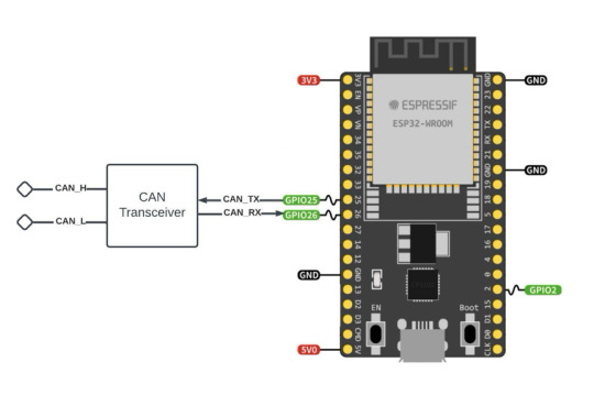
The ESP32 includes a CAN Bus controller compatible with the NXP SJA1000, making it compliant with the CAN 2.0B (ISO 11898, also known as Classical CAN) specification.
Nevertheless, as with the SJA1000, the ESP32 CAN Bus controller only provides the data link layer and the physical layer signaling sublayer. As a result, an external transceiver module is needed to convert the ESP32's CAN-RX and CAN-TX signals into CAN_H and CAN_L bus signals.
#can bus#can fd#esp32#wroom-32#CAN Transceiver#Embedded System#Embedded Development#SJA1000#Classical CAN#Bluetooth#BLE#WiFi#IoT
1 note
·
View note
Text
#Espressif#esp wifi module#esp32 wroom 32d#esp 32 wroom 32d#esp wroom32d#buy electronic components online#electronic components online in india#buying electronic components online#buy electronic components online india
1 note
·
View note
Text
Looking at this as a way to add some extra buttons and a cursor (trackball, touchpad or joystick) to a normal phone by using the usb otg port for the keys and gpio pins for the cursor and communicating over bluetooth. The idea would be to have an adjustable clip on enclosure that goes on the back of the phone (with some specific design stuff to make it ergonomic)
12 notes
·
View notes
Text
DIY: Marauder with Screen and GPS For Flipper Zero
Many of you would have seen the humongous ESP32 add-on module with touch screen and GPS for Flipper Zero shared in discussion groups, forums, etc. Well, this tutorial will provide you with all the information you need to build one yourself.
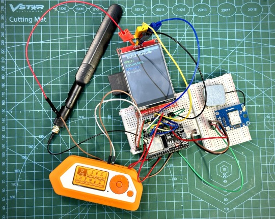
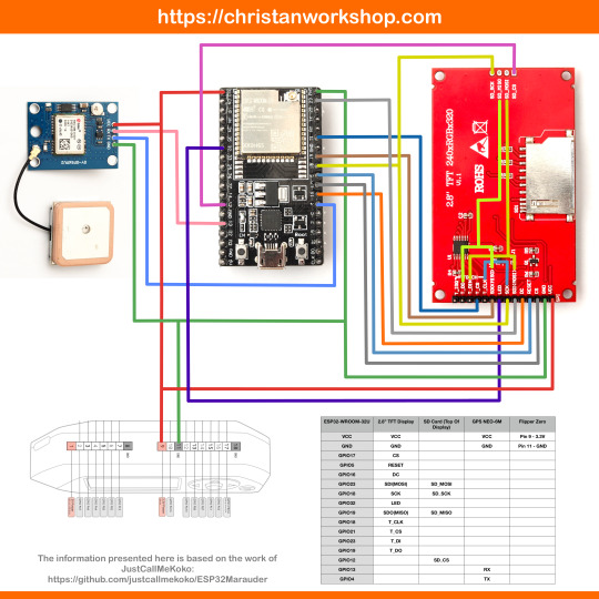
This build consists of mainly 4 parts. The TFT LCD 2.8" 240x320 SPI ILI9341 Touch Display cost me around US$5.50, the ESP32-WROOM-32U module cost around US$3, the NEO-6M GPS module cost around US$2.20 and an 8dbi 2.4GHz Wifi Antenna which cost around US$2. All of these parts can be easily found in online marketplaces like Aliexpress, Amazon, etc. Here is how you need to wire them up together. How you wish to lay this out or mount on a prototyping board is entirely up to you. As long as the connections are correct, you are good to go. The GPS module is optional, and mainly, it's used for the war driving functionality.
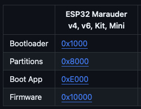
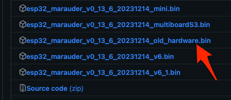
Next, you need to download all the firmware needed from here. Please download the Bootloader, Partitions, Boot App and Firmware files for v4 (Yes, v4 files, not any others) and save it on your computer.
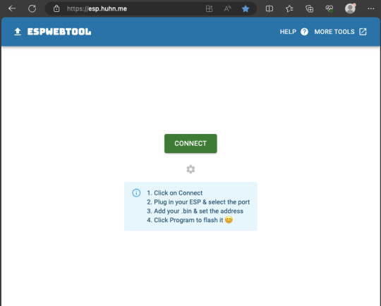
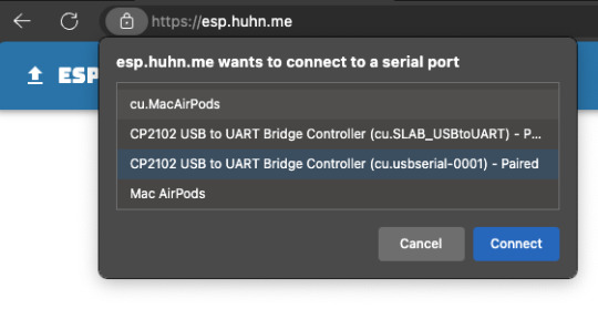
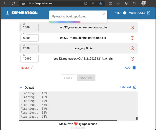
Now, press and hold the BOOT button on your ESP32-WROOM-32U module and connect it to your computer using a data-capable USB cable (some USB cables can only charge), then let go the BOOT button. Open Google Chrome or Microsoft Edge browser and go to ESPWebTool. Click the CONNECT button, then select the ESP32 usb serial connection. It should look something like below but can vary a little between different computers and operating systems.
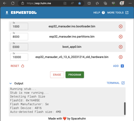
Select the firmware files for each slot exactly like below (take note of the 0x1000, 0x8000, etc. and their corresponding .bin files), then hit the PROGRAM button.
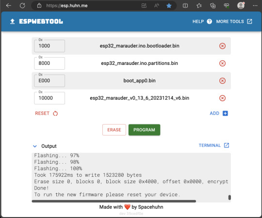
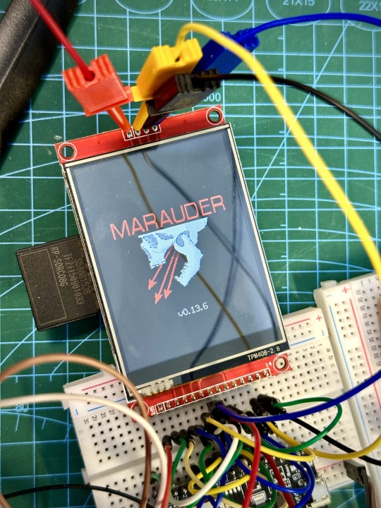
When completed successfully, you can unplug the USB cable from the ESP32 module and now you can connect your Marauder module to your Flipper Zero. Please ensure that your Flipper Zero is turned off before you connect it, and also turn off your Flipper Zero before disconnecting it. The 3.3V pin is also used by your Flipper Zero's SD card reader and connecting/disconnecting external modules that use this pin while the Flipper Zero is on can potentially corrupt the SD card. So, if everything went according to plan, your Marauder module should boot up and everything should look like below.
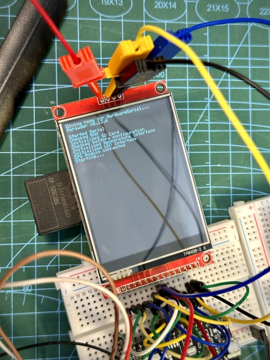
NOTE: If your Marauder boots up, but when you try to touch the screen and get no response, try tapping around the bottom part of your screen and see if the touch panel seems to be in inverted position from the actual display. Should this happen to you, just flash your ESP32 module again following the steps above, but use the v6 firmware. This should resolve the issue.
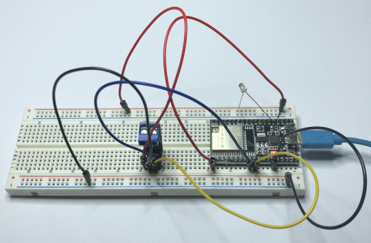
In this build, I just prototyped this on breadboard, but you can of course make it permanent by soldering it on to a prototype board and 3D print a case for it. This setup is essentially just using the Flipper Zero as a battery pack, instead of using the Flipper Zero to control Marauder. The large screen does make some things easier to do, compared to the small screen of the Flipper Zero, and there may be some functionality (not much) that is not currently in the Flipper Zero Marauder companion app. Here is a video showing the different menus in Marauder.
Personally, I don't think I will actually want to bring something so big around with me, along with my Flipper Zero. I think what makes Flipper Zero special is just how compact it is and all the different functionality cramped into it. This would probably be better off as a standalone unit by just hooking up a battery, but that's just me. Well, that's it for this tutorial. I hope you found this helpful.
Here's a good intro to Marauder if you are unfamiliar.
youtube
18 notes
·
View notes
Text
Matrix portal s3 shifting sand 🔀📲📅⏳💔🔄🔌💡🏜️🆕
We're slowly but surely trying to de-SAMD51'ify our product line since that chip has a 2024 ETA. a bummer because we really loved that chip but it's probably a good time to transition since it can be a year until we get some and even then, the dates have been pushed multiple times. so, first up is the matrix portal m4 https://www.adafruit.com/product/4745 ! instead of a samd51 + esp32, we've got a version with ESP32-S3 WROOM which has 8MB of flash, and 2MB of PSRAM. the S3 has a nice peripheral that can be used to drive these matricies very fast, and the 2 MB of PSRAM will make this possible to drive lots of panels! we kept the same outline shape and functionality, including the built in accelerometer, which makes this LED sand demo a quick port.
18 notes
·
View notes
Text
The ESP32 is a development board developed by Espressif systems. It can be programmed using Arduino IDE and ESP-IDF. It has higher processing power than ESP8266 but it is more costly and bigger in physical dimension than ESP8266. It has a built in Bluetooth module and CAN protocol and SRAM. It has 36 GPIO Pins with a CPU clock of 160MHz. It has 12-bit ADC onboard and supports CAN, UART, I2C and I2S. It can be used in prototyping IoT products, Low power Battery operated application, small range networking projects, and with the projects which require many Input Output Pins and Wi-Fi and Bluetooth connectivity.
6 notes
·
View notes
Text

🚨 Schneider XACA201 Emergency Stop Switch! ⚡
Looking for a reliable Emergency Stop (E-Stop) Switch for your industrial operations? The Schneider XACA201, available at Xon Electronics, is your go-to solution for safety and control in critical situations. 🌐 Shipped worldwide including the USA, India, Australia, Europe, and more!
🔧 Specifications:
Type: Pendant Station E-Stop
Current Rating: 10A
Voltage Rating: Up to 600VAC
Mushroom-head red emergency stop pushbutton
Material: Impact-resistant plastic
Mounting Style: Handheld pendant
Manufacturer: Schneider Electric
⭐ Key Features:
Instant machine shutdown in emergencies
High visibility & easy-to-activate pushbutton
Rugged build for industrial environments
Ergonomic handheld design
Compliant with global safety standards
🏭 Applications:
Overhead cranes & hoists
Conveyor belts & assembly lines
Lifting equipment
Factory automation & control systems
🛒 Available now at Xon Electronics!
Buy Now: https://www.xonelec.com/mpn/schneider/xaca201
Learn More: https://www.xonelec.com/blog/esp32-wroom-32e-embedded-wifi-modules-by-espressif
#EmergencyStopSwitch #SchneiderElectric #XACA201 #XonElectronics #IndustrialSafety #EStopSwitch #AutomationSafety #CraneControls #FactoryAutomation #WorldwideShipping
0 notes
Text
ESP32-WROOM-32: The Tiny Powerhouse for Your Next IoT Project! 🚀🔧
Looking for a microcontroller that packs a punch? The ESP32-WROOM-32 is your best bet! 💡 This Wi-Fi + Bluetooth-enabled module is perfect for IoT, robotics, and home automation. With its dual-core processor, low power consumption, and tons of GPIO pins, it's a maker's dream. Whether you're building a smart gadget or diving into edge computing, this little beast can handle it all!
🔥 Why choose ESP32-WROOM-32? ✅ Dual-core performance ✅ Built-in Wi-Fi & Bluetooth ✅ Low power consumption ✅ Tons of connectivity options
What cool projects are you making with it? Let’s discuss! 🛠️✨ #ESP32 #IoT #DIYTech
#ESP32#Microcontroller#IoT#EmbeddedSystems#ESP32WROOM32#Electronics#DIYProjects#Arduino#WiFiModule#Bluetooth#SmartDevices#HomeAutomation#ESP32Projects#Tech#CircuitDesign
0 notes
Text
UHF Reader Based on Pico W & ESP32 with 50 Tags/Second Reading within 1.5 Meter Range

A UHF Reader (Ultra High Frequency Reader) is a device that is used to read and write data from UHF RFID tags within the 860MHz-960MHz frequency range. It is a multi tags 50 tags/second reading/writing device within 1-1.5 meter range designed with cutting edge UHF technology. It is a compact, portable and easy to use device.
The UHF reader has 2 variants: one is UHF Reader by Pico W and another is UHF Reader by ESP32. The Pico W variant comes with RP2040 microcontroller with Wi-Fi and BLE support. It is compatible with MicroPython, CircuitPython and Arduino for programming. ESP32 variant comes with ESP32 S3 series microcontroller and has 2.4GHz & Bluetooth 5 (LE) support. It is compatible with Arduino and Espressif IDE for programming.
Key Features and Specifications:
UHF Reader Pico Variant:

Powered by Raspberry Pi Pico W
RP2040 microcontroller dual-core Arm Cortex M0+ microprocessor with 264kB RAM
Supports Wi-Fi and BLE
1.14” TFT display for better visualization
Multi-tone buzzer for audio alerts
Micro USB Support for programming & Type C support for power
3 programmable buttons and Reset button
SD card slot for data storage/transfer
LED Status for power and battery charging
Multipurpose GPIOs breakout for interfacing external peripherals
SWD pins breakout for serial debugging
Supports MicroPython, CircuitPython, and Arduino for programming
UHF Reader ESP32 Variant:

Powered by ESP32 S3 WROOM-1
Dual-core 32 bit LX7 microprocessor with Up to 8 MB PSRAM and up to 16 MB flash memory
Supports 2.4GHz (802.11b/g/n) Wi-Fi and Bluetooth 5 (LE)
1.14” TFT display with ST7789 display driver
Comes with a Read and Write UHF module.
Frequency range of 865.1MHz-867.9MHz (for EU/UK) and 902.25MHz-927.75MHz (for US)
Can Identify 50 tags/second up to the 1.5-meter range.
TTL UART communication interface and communication baud rates 115200bps-38400bps
output power 18-26dBm and output power accuracy +/- 1dB
operation current 180mA at 3.5V (26 dBm Output), 110mA at 3.5V (18 dBm Output)
Multi-tone buzzer for audio alerts
2 user programmable buttons, Boot and Reset buttons
For power and programming support, the Type C Interface
SD Card slot for data transfer/storage
LED status for power and charging
Multipurpose GPIOs breakout for interfacing external peripherals
Supports Arduino and Espressif IDE for programming
By using ESP32 and RP2040, you can build a UHF RFID reader for scan tags and data tracking. This UHF Reader with ESP32 and Pico by SB Components is suitable for applications like warehouses, retail stores, and many other applications where you want to track your inventory data accurately.
#technology#innovation#tech#iot#rfid#uhf#uhf reader#arduino#espressif#iot applications#raspberry pi#rp2040#esp32#projects#programming#ultra high frequency reader#rfid tags#data tracking#electronics
1 note
·
View note
Text
ESP32: Zurück von MicroPython zur Arduino IDE in nur einem Schritt

Der ESP32 ist ein vielseitiger Mikrocontroller, der sich flexibel mit verschiedenen Umgebungen programmieren lässt – darunter MicroPython, CircuitPython, LuatOS und mehr. Wenn du deinen ESP32 nach dem Flashen mit einer dieser Firmwares wieder in der Arduino IDE programmieren möchtest, zeige ich dir hier, wie du in wenigen Schritten den gesamten Speicher überschreibst und so den Wechsel einfach machst. https://youtu.be/wlYsI5ma7Qo In diesem Beitrag verwende ich einen ESP32-WROOM-32, der standardmäßig bereits für die Programmierung in der Arduino IDE vorbereitet ist. Für ein kleines Projekt habe ich ihn zunächst mit der aktuellen MicroPython-Firmware geflasht. Jetzt möchte ich wieder zur Arduino IDE wechseln – und das geht erfreulich einfach.

Mikrocontroller - ESP32 WROOM 32 Für diesen Wechsel benötigst du lediglich die Arduino IDE – entweder die klassische Version oder die neue 2.x-Version. Zuerst installieren wir den passenden Boardtreiber und wählen dann unter Werkzeuge > Board > ESP32 das richtige Modell aus. Danach legen wir den Port fest und können direkt das angezeigte leere Programm auf den ESP32 hochladen. Zusätzliche Bordverwalter URL für den Boardtreiber: https://raw.githubusercontent.com/espressif/arduino-esp32/gh-pages/package_esp32_index.json Alternativ kannst du auch dieses einfache Programm verwenden: Es lässt die interne LED des ESP32 alle 0,5 Sekunden blinken und gibt gleichzeitig die Nachricht „Hallo, aus der Arduino IDE“ auf der seriellen Schnittstelle aus. // interne LED des ESP32 mit dem GPIO02 verbunden #define led 2 void setup() { //beginn der seriellen Kommunikation mit 115200 baud Serial.begin(115200); //Pin der LED als Ausgang definieren pinMode(led, OUTPUT); //Ausgabe des Textes auf der seriellen Schnittstelle Serial.println("Hallo, aus der Arduino IDE"); } void loop() { //aktivieren der LED digitalWrite(led, HIGH); //eine kleine Pause von 0,5 Sekunden delay(500); //deaktivieren der LED digitalWrite(led, LOW); //eine kleine Pause von 0,5 Sekunden delay(500); } Die Ausgabe auf der seriellen Schnittstelle sollte wie folgt sein: Hallo, aus der Arduino IDE Wenn du den Mikrocontroller über die RESET- oder BOOT-Taste neu startest, kann es vorkommen, dass zusätzliche Ausgaben erscheinen – diese stammen vom Mikrocontroller selbst. Um dies zu vermeiden, kannst du die Baudrate in der seriellen Konsole beispielsweise auf 9600 setzen; so sollte diese Meldung nicht mehr angezeigt werden. ets Jul 29 2019 12:21:46 rst:0x1 (POWERON_RESET),boot:0x13 (SPI_FAST_FLASH_BOOT) configsip: 0, SPIWP:0xee clk_drv:0x00,q_drv:0x00,d_drv:0x00,cs0_drv:0x00,hd_drv:0x00,wp_drv:0x00 mode:DIO, clock div:1 load:0x3fff0030,len:4832 load:0x40078000,len:16460 load:0x40080400,len:4 load:0x40080404,len:3504 entry 0x400805cc
Fazit - von MicroPython zur Arduino IDE am ESP32
Mit wenigen, einfachen Schritten lässt sich der ESP32 von MicroPython zurück auf die Arduino IDE umstellen. So bleibt der Mikrocontroller flexibel für verschiedene Projekte und Entwicklungsumgebungen einsetzbar. Diese Anleitung zeigt dir, wie der Wechsel gelingt und stellt sicher, dass du schnell und ohne Umwege zwischen den Programmiertools wechseln kannst. Read the full article
0 notes

Text
0 notes
Text
CAN Bus Development with ESP32-WROOM32 Development Board
The ESP32 WiFi, Bluetooth Classic, BLE, CAN Bus Module comes with an onboard ESP32 WROOM-32 WiFi, Bluetooth Classic, BLE Module, and a CAN Bus port with a transceiver. The programming is accomplished through the popular Arduino IDE connected to the USB-to-Serial converter with a USB-C connector, automatic bootloader, and reset.
#can bus#classic can#esp32#embedded programming#embedded systems#wroom32#wifi#ble#bluetooth#usb#gateway#iot
1 note
·
View note
Text
Building Custom HomeKit Devices

Have you ever caught yourself thinking, “I wish there was a HomeKit device that could do this…”? Yeah, same here. For me, it was wishing my washer-dryer could send a notification when the laundry’s done. See, it’s out in the yard—so if you’re chilling in the living room with the TV on, you’d never hear the washing machine’s faint beep of completion.
Luckily, I had a few ESP32s and sensors collecting dust in a drawer, so I thought: Why not build one myself? With a little help from AI, of course. I’ve been bouncing between Gemini 2.5 Pro, Grok, and ChatGPT, and they’ve been surprisingly great sidekicks. Sure, I could’ve sat down and studied all the libraries and frameworks properly—it might’ve taken me a couple of days tops (I’ve been around the programming and electronics block a few times). But thanks to AI, I hacked together a working prototype in just a few hours.
Now, this isn’t a tutorial—that’s coming soon once I’ve fine-tuned everything and properly tested my DIY HomeKit setup. This is more of a quick peek behind the curtain. A little show and tell.


For the build, I used an ESP32-S3 WROOM-1 (N16R8) and an MPU6050 3-axis accelerometer. Total cost? Around 7 bucks. Hooking up the sensor via I2C was simple enough. When any of the AIs got confused or hit a wall, I just tag-teamed between them until I got what I needed.
And here’s the result after just a few hours of tinkering—Apple’s Home app picked up my custom HomeKit device without a hitch. The best part? Seeing “ChrisTan Workshop” proudly listed as the manufacturer. Cracked me up. Nothing like a bit of DIY flair baked right into the Home app!


Here’s a quick rundown of how the magic works: the MPU6050 accelerometer monitors for vibrations. If it detects continuous movement for more than 20 seconds, we assume the washing machine is doing its thing and mark it as “running.” Once it stays still for over 3 minutes, we take that as a sign that the laundry’s done. These timings—and a few other parameters—are all configurable. I’m still fine-tuning them to match the quirks of my Electrolux washer dryer.
One of the trickier parts (and where all the AIs struggled a bit) was figuring out how to send a proper HomeKit notification. After some back-and-forth, we found a clever workaround: register the device as a doorbell. That way, when the laundry finishes, my HomePod mini chimes and a notification pops up like someone’s at the door. Not exactly elegant, but hey—it works! I just wish HomeKit gave us more flexibility with custom notifications, but I get it… Apple’s probably trying to prevent spammy alerts from rogue accessories.

That’s it for now. Eventually, I want to make this whole thing easily user-configurable—no coding required. But for the moment, a few parts are still hard-coded under the hood.
0 notes
Text

Chonkiest ESP32-S3 Metro is pulling into the station and it is piled high with PSRAM 🚂💾🔌
This ESP32-S3 metro brings the chonk, with 16 MB of Flash and 8 MB of PSRAM - that's the max you can get in the WROOM module . but we think it's worth it's weight in gold cause when we start messing around with the parallel TTL TFT driver we're gonna need that space to buffer the full 16 bit 800x480 display… heck we could even double buffer the graphics at that point.
Lots of power options here, too: 6-12V DC jack with on-off switch, USB type C or lipoly battery . the lipoly can be charged on board and monitored with a MAX17048 .
One frustration from our Metro ESP32-S2 is that the Espressif Arduino board support package never added pin-reordering, so in this Metro we use consecutive numbered pins from 2-13 so shield pin configurations don't have to change.
For IoT datalogging projects we Stemma QT I2C & a micro SD card socket. We also added a JTAG connection and the hardware UART debug pins in case we have to do some more-than-printf debugging. All the edges are so packed full of stuff that we had to stick the boot0 button and D13 / ON LEDs in the middle!
#adafruit#electronics#pcb#opensource#opensourcehardware#pcboftheday#espressif#esp#esp32s3#arduino#metro#esp32s3metro#psram#flashstorage#iotdatalogging#electronicboard#usbtypec#parallelttft#debugging#arduinosupport#jtagconnection
4 notes
·
View notes
Text
Discover the Power of Connectivity: ESP32S WIFI BLE Board-V1.0
Unleash the potential of your projects with the ESP32S WIFI BLE Board-V1.0, a versatile and robust solution designed to revolutionize the world of wireless communication. This development board is built around the powerful ESP-WROOM-32, a Wi-Fi+BT+BLE MCU module that brings a new dimension to your applications, from low-power sensor networks to complex tasks like voice encoding, music streaming, and MP3 decoding.
The ESP32S WIFI BLE Board-V1.0 empowers you to break free from limitations. With its comprehensive features and capabilities, it is the perfect choice for a wide range of applications. Embrace its prowess in low-power sensor networks or let it tackle high-demanding tasks with ease. The dual-core architecture, running at an impressive 160MHz, opens up new horizons, while an abundance of pins and peripherals ensures you're equipped to handle whatever comes your way.
One of the standout features of the ESP32S WIFI BLE Board-V1.0 is the integration of Bluetooth, Bluetooth LE, and Wi-Fi. This harmonious blend ensures that your projects are future-proof, capable of addressing a diverse array of applications. Utilizing Wi-Fi extends your physical reach and allows direct connectivity to the internet via a Wi-Fi router. Meanwhile, Bluetooth connectivity brings the convenience of connecting to smartphones and the versatility of broadcasting low-energy beacons for effortless detection.
With the ESP32 chip's sleep current clocking in at less than 5 µA, the ESP32S WIFI BLE Board-V1.0 is primed for battery-powered and wearable electronics applications. This means that your creations can operate longer on a single charge, offering enhanced efficiency and sustainability. The support for data rates of up to 150 Mbps and an impressive 22 dBm output power at the PA ensures unparalleled connectivity and an extended physical range.
Indulge in the industry-leading specifications and performance that the ESP32S WIFI BLE Board-V1.0 brings to the table. The fusion of electronic integration, range, power consumption, and connectivity sets new standards for wireless communication solutions. No matter the complexity of your projects, this board is engineered to exceed expectations, making it the ultimate choice for forward-thinking innovators.
Are you ready to embark on a journey of connectivity and innovation? Embrace the future with the ESP32S WIFI BLE Board-V1.0, where your possibilities are limitless, and your projects are poised for greatness. Elevate your creations and embrace the world of wireless communication like never before.
0 notes