#esp wifi module
Explore tagged Tumblr posts
Visit Tumblr Blog
Explore Tumblr blogs with no restrictions, modern design and the best experience.
Last Seen Tumblr Blogs


Fun Fact
There were a total of 171.5 billion posts on Tumblr in 2019.
Text
#Espressif#esp wifi module#esp32 wroom 32d#esp 32 wroom 32d#esp wroom32d#buy electronic components online#electronic components online in india#buying electronic components online#buy electronic components online india
1 note
·
View note
Text
OOOh, some hot new chips just dropped into our mailbox - ESP32-P4! 🔥🚀
Espressif's latest chip has a snazzy eval board, and we just snagged a couple for CircuitPython development. The P4 is a RISC V dual core 400MHz processor with CSI/DSI support, USB HS, and Ethernet too. This chip doesn't have BLE or WiFi like all the other ESP chips. Instead, it uses a low-cost ESP32-C5 module as a wireless co-processor. The eval board is sorta shaped like a Raspberry Pi and has various A/V connections. We also got 100 sample chips of the 16MB in-package PSRAM variety, so we can start designing our first board. Shall we do a Feather? a Metro? maybe a Pi Zero-shaped thingy?
#espressif#esp32#ESP32P4#espfriends#adafruit#greetz#circuitpython#hardwaredesign#microcontroller#techinnovation#riscv#developmentboard#diyelectronics#opensourcehardware#embeddedsoftware#chipdesign
3 notes
·
View notes
Text
DIY: Easiest Standalone Deauther

Previously, I have built a standalone Deauther with an OLED display and buttons over here, but realistically, everyone is just going to use the web interface. So, I recently found an ESP8266 ESP-07 USB module that is perfect for a standalone Deauther, since it has a USB connector built-in and you can just plug it into any powerbank. This module cost me around USD3 and you can find it in AliExpress.


First, we need to download the Deauther firmware. Go to this page and download this file: esp8266_deauther_2.6.1_DSTIKE_NODEMCU_07_V2.bin
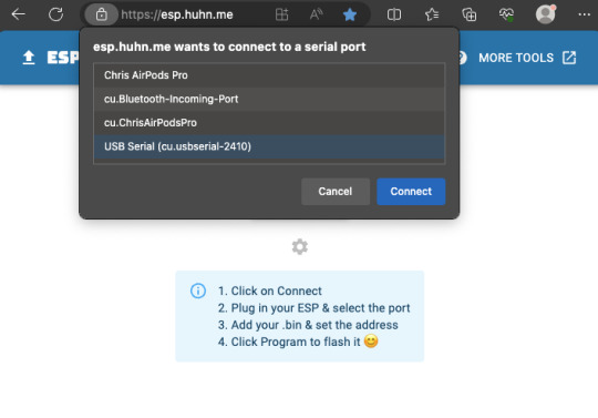
Next, set the switch on the ESP module to "PROG" and plug it into your computer's USB. Run Google Chrome or Microsoft Edge browser and go to https://esp.huhn.me. Click CONNECT and select the USB Serial item and click Connect.

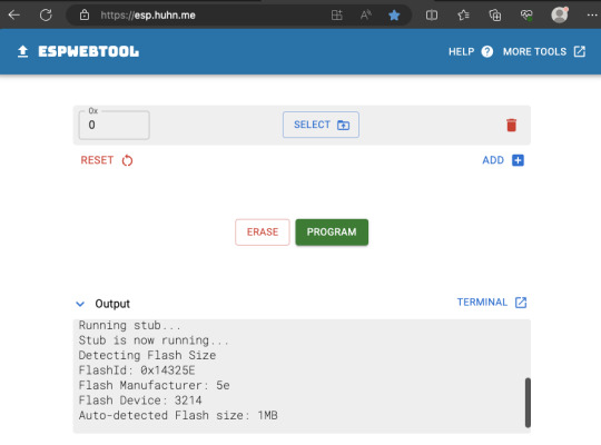
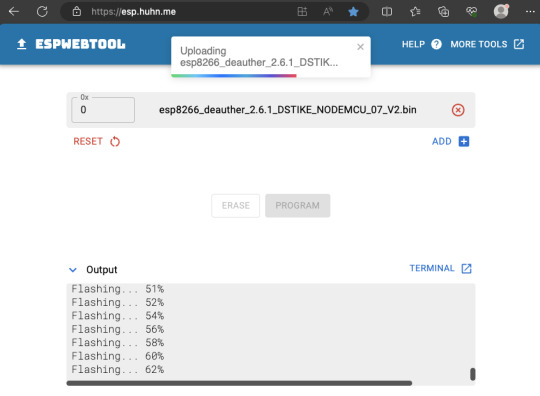
Now that it has successfully connected, click SELECT and choose the firmware file you downloaded earlier, then hit the PROGRAM button.

It should now start flashing, so just let it finish the job.
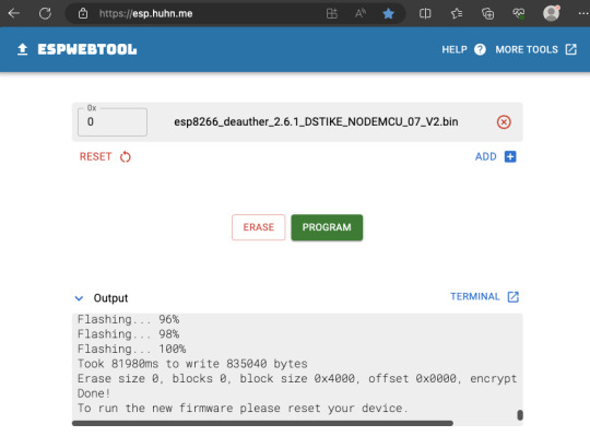
Finally, flick the switch on the ESP module from PROG to UART, and hit the reset button on the ESP module while still plugged into USB, or you can just remove it from your computer and plug it into a powerbank. On your phone/computer, just connect to the Wifi network "pwned" and use "deauther" for the password. Then open your web browser and go to http://192.168.4.1


That's it! You now have a standalone Deauther. More information about using the web interface over here. Also, realize that in most countries, there are laws against disrupting communication networks and Deauth attacks may be illegal.
4 notes
·
View notes
Text
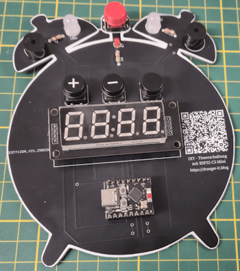
ESP32-C3 Mini: Die perfekte Basis für eine moderne Timerschaltung

In einem früheren Beitrag habe ich mit der Arduino-gestützten Eieruhr bereits eine flexible Countdown-Anzeige mit akustischem Alarm vorgestellt. Die ursprüngliche Version, die ich auf meinem Blog unter diesem Link veröffentlicht habe, basierte auf einem klassischen Arduino. Doch nun wird es Zeit für ein Upgrade: Der ESP32-C3 Mini bietet nicht nur mehr Leistung mit seinen 160 MHz, sondern bringt auch WiFi- und Bluetooth-Konnektivität mit – und das in einem äußerst kompakten Format. https://youtu.be/5CGeBJfi6Gc Die Portierung der bestehenden Arduino-Schaltung auf den ESP32-C3 Mini war erstaunlich einfach, da dieser ebenfalls in der Arduino IDE programmiert werden kann. Der eigentliche Fokus lag jedoch darauf, die Schaltung auf eine eigene Platine (PCB) zu bringen, um sie für ein bevorstehendes Event im JFZ Schöningen einsatzbereit zu machen.
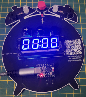
In diesem Beitrag zeige ich, wie die Timerschaltung mit dem ESP32-C3 Mini realisiert wurde, welche Anpassungen notwendig waren und wie die finale Version als fertige Platine umgesetzt wurde.
Warum der ESP32-C3 Mini besser als ein Arduino ist
Zunächst einpaar Gründe warum der ESP32-C3 Mini besser als ein Arduino ist: ✔ WiFi & Bluetooth integriert – Kein extra Modul nötig, ideal für IoT. ✔ Mehr Leistung & Speicher – 160 MHz, 384 KB RAM vs. 16 MHz, 2 KB RAM beim Arduino. ✔ Energieeffizient – Sleep-Modi für geringen Stromverbrauch. ✔ Vielseitigere GPIOs – Mehr analoge Eingänge, PWM, SPI, I2C, UART gleichzeitig nutzbar. ✔ Moderne Programmierung – Neben der Arduino IDE auch MicroPython & ESP-IDF unterstützt.
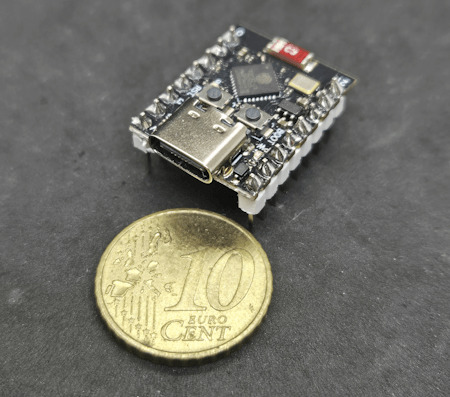
ESP32-C3 Super Mini
Benötigte Bauteile für die Timerschaltung
Für den Aufbau der Schaltung werden folgende Komponenten benötigt. Diese ermöglichen eine einfache Umsetzung und sind flexibel auf einem 800-Pin-Breadboard testbar. - 1x ESP32-C3 Mini – Der Mikrocontroller als Steuerzentrale - 4x Taster mit Köpfen – Zur Steuerung der Timer-Funktionen - 1x 3mm LED mit 220-Ohm-Vorwiderstand – Statusanzeige - 2x 5mm LED mit 220-Ohm-Vorwiderstand – Visuelles Feedback beim Alarm - 2x Piezo-Buzzer – Akustischer Signalgeber - diverse Breadboardkabel – Zur Verbindung der Komponenten - 1x 800-Pin-Breadboard – Für eine flexible Verdrahtung Hinweis von mir: Die mit einem Sternchen (*) markierten Links sind Affiliate-Links. Wenn du über diese Links einkaufst, erhalte ich eine kleine Provision, die dazu beiträgt, diesen Blog zu unterstützen. Der Preis für dich bleibt dabei unverändert. Vielen Dank für deine Unterstützung!
Timerschaltung am Schaltung am ESP32-C3 Mini im Detail
Nachfolgend die Timerschaltung am ESP32-C3 auf einem Breadboard.
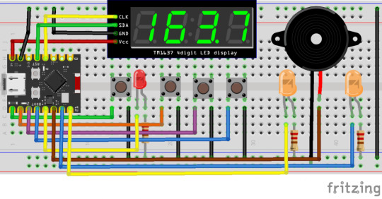
ESP32-C3 Mini - Countdown Schaltung Bauteil / PinESP32-C3 Mini4fach 7 SegmentanzeigeCLK > 3 (GPIO3) SDA > 4 (GPIO4) GND > GND VCC > 5VTaster - Start / Stopp5 (GPIO5)Taster - Plus6 (GPIO6)Taster - Minus7 (GPIO7)Taster - Select8 (GPIO8)LED 120 (GPIO20)LED 221 (GPIO21)Status LED9 (GPIO9)Piezo Buzzer - links10 (GPIO10)Piezo Buzzer - rechts2 (GPIO2) Pinout des ESP32-C3 Mini Nachfolgend findest du den Aufbau des ESP32-C3 Mini, der dir hilft, die richtigen Pins für deine Schaltung schneller und einfacher zu identifizieren. Eine klare Übersicht der GPIO-Belegung erleichtert die Verdrahtung und reduziert Fehler beim Anschluss der Komponenten.
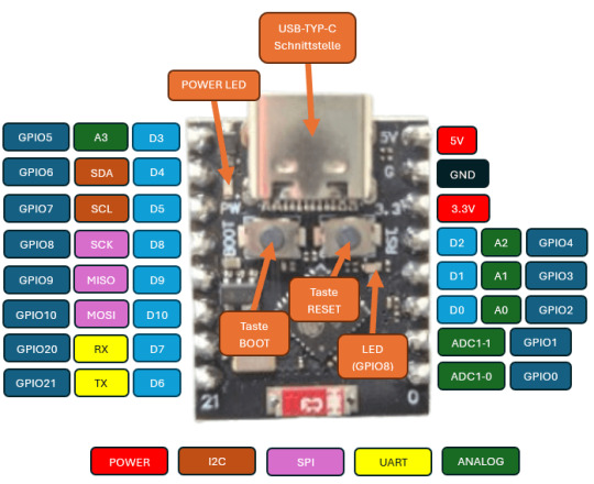
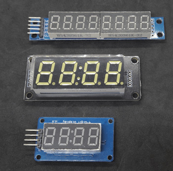
ESP32-C3 Pinout Falls du spezielle Funktionen wie PWM, I2C, SPI oder UART nutzen möchtest, lohnt sich ein Blick auf die multiplen Belegungsmöglichkeiten der Pins. Unterschiedliche - 4fach 7Segmentanzeigen Es gibt verschiedene Arten von 7-Segment-Anzeigen auf dem Markt. Einerseits gibt es kompakte, einfache Modelle, andererseits größere Varianten mit farbigen Segmenten. Für dieses Projekt entscheide ich mich für die größere Version, da sie nicht nur besser lesbar ist, sondern durch die unterschiedlichen Farben auch optisch ansprechender wirkt und das Projekt aufwertet.
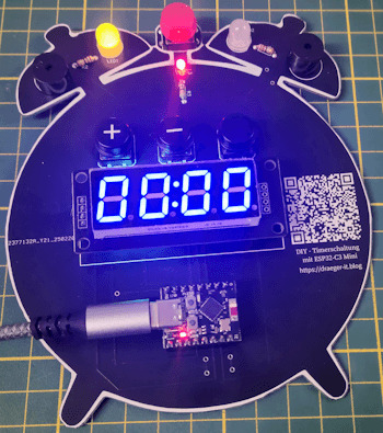
Ausbau einer LED In der Schaltung kommen drei LEDs zum Einsatz, die sich durch ihre hohe Leuchtkraft und lange Lebensdauer auszeichnen. Sie dienen nicht nur als Statusanzeige, sondern ermöglichen auch eine visuelle Rückmeldung über den aktuellen Betriebszustand der Timerschaltung. Die LEDs werden über einen GPIO-Pin des ESP32-C3 Mini angesteuert und mit einem 220-Ohm-Vorwiderstand in Reihe geschaltet, um den Stromfluss zu begrenzen und die Lebensdauer der LEDs zu erhöhen. Durch diese Beschaltung ist sichergestellt, dass die LEDs effizient betrieben werden, ohne den Mikrocontroller zu überlasten. Beim Einbau einer LED ist darauf zu achten, dass sie richtig gepolt angeschlossen wird. Die Kathode (Minuspol) wird mit dem Vorwiderstand verbunden, der anschließend an GND führt. Die Anode (Pluspol) hingegen wird direkt mit dem entsprechenden GPIO-Pin des ESP32-C3 Mini verbunden. Eselsbrücke: Die Kathode erkennt man am kürzeren Bein der LED.

Aufbau einer LED Falls du mehr über die Funktionsweise und den Anschluss von LEDs erfahren möchtest, findest du eine detaillierte Erklärung auf der Seite "Bauteile: Leuchtdiode (LED)", wo ich dieses Bauteil ausführlich vorstelle.
Programmieren in der Arduino IDE
Wie bereits erwähnt, habe ich dieses kleine Projekt zuvor für den Arduino entwickelt und programmiert. Dadurch war die Portierung auf den ESP32-C3 Mini relativ unkompliziert – es mussten lediglich die Pinbelegungen angepasst werden. Eine zusätzliche Optimierung bestand darin, die Start- und Stopp-Funktion auf einen einzigen Taster zu legen, anstatt zwei separate Taster zu verwenden. Dadurch spart man nicht nur einen GPIO-Pin, sondern macht die Bedienung auch kompakter und effizienter. Dies ist besonders vorteilhaft, da der ESP32-C3 Mini im Vergleich zu einem klassischen Arduino weniger verfügbare GPIOs hat. Programm: Timerschaltung am ESP32-C3 Mini in der Arduino IDEHerunterladen fertiges Programm für eine Timerschaltung am ESP32-C3 Mini /* * Autor: Stefan Draeger * Webseite: https://draeger-it.blog * Beitrag: https://draeger-it.blog/esp32-c3-mini-die-perfekte-basis-fuer-eine-moderne-timerschaltung/ * * Beschreibung: * Diese Firmware steuert eine Timerschaltung mit einer 7-Segment-Anzeige (TM1637), * Tastern zur Zeiteinstellung, LEDs zur Statusanzeige und einem akustischen Alarm über einen Buzzer. * Die Zeit kann in Sekunden oder Minuten eingestellt und per Start/Stopp-Taste gesteuert werden. * * Funktionen: * - Anzeige der verbleibenden Zeit auf einer TM1637 7-Segment-Anzeige * - Steuerung der Zeit über Taster (Erhöhung/Verringerung in Sekunden oder Minuten) * - Akustischer Alarm nach Ablauf des Timers mit abwechselnden LED-Signalen * - Speicherung und Aktualisierung des Timers in der Loop * - Start/Stopp-Funktion für den Timer */ #include // Bibliothek für 7-Segment-Anzeige TM1637 #include // Bibliothek für die Taster-Entprellung // Definition der LED-Pins #define led1 20 #define led2 21 // Definition der Pins für die 7-Segment-Anzeige (TM1637) #define segmentanzeige_CLK 3 #define segmentanzeige_DIO 4 TM1637Display display(segmentanzeige_CLK, segmentanzeige_DIO); // Anzeige-Objekt erstellen // Definition der Taster-Pins #define tasterStartStopp 5 #define tasterPlus 6 #define tasterMinus 7 #define tasterSelect 8 // Taster-Objekte für die Entprellung Bounce bceTasterStartStopp = Bounce(); Bounce bceTasterPlus = Bounce(); Bounce bceTasterMinus = Bounce(); Bounce bceTasterSelect = Bounce(); // Definition der Pins für Buzzer und Status-LED #define buzzerLeft 10 #define buzzerRight 2 #define statusLed 9 // Variablen für die Timer-Logik unsigned int timeAuswahl = 0; // Auswahlmodus für Zeit (Sekunden/Minuten) unsigned int seconds = 0; // Aktuelle Zeit in Sekunden const unsigned int PAUSE = 1000; // Zeitintervall für Timer-Update (1 Sekunde) const unsigned int PAUSE_ALARM = 250; // Zeitintervall für Alarmton unsigned long lastAction = 1L; // Zeitstempel für letzte Aktion bool clockStarted = false; // Timer läuft oder nicht bool clockAlarm = false; // Alarmstatus bool lastStateLED = false; // Zustand der LEDs für Alarm void setup() { // Setzt die Pin-Modi für LEDs, Buzzer und Status-LED pinMode(led1, OUTPUT); pinMode(led2, OUTPUT); pinMode(buzzerLeft, OUTPUT); pinMode(buzzerRight, OUTPUT); pinMode(statusLed, OUTPUT); // Helligkeit der 7-Segment-Anzeige einstellen (0-7, hier maximale Helligkeit) display.setBrightness(7); // Anzeige mit allen Segmenten aktivieren (zum Test) uint8_t data = { 0xff, 0xff, 0xff, 0xff }; display.setSegments(data); // Taster mit Pullup-Widerständen initialisieren und Entprellzeit setzen bceTasterStartStopp.attach(tasterStartStopp, INPUT_PULLUP); bceTasterStartStopp.interval(5); bceTasterPlus.attach(tasterPlus, INPUT_PULLUP); bceTasterPlus.interval(5); bceTasterMinus.attach(tasterMinus, INPUT_PULLUP); bceTasterMinus.interval(5); bceTasterSelect.attach(tasterSelect, INPUT_PULLUP); bceTasterSelect.interval(5); // LEDs und Status-LED ausschalten digitalWrite(led1, LOW); digitalWrite(led2, LOW); digitalWrite(statusLed, LOW); displayTime(); // Startanzeige aktualisieren } // Zeigt die aktuelle Zeit auf der 7-Segment-Anzeige an void displayTime() { int minutes = seconds / 60; // Maximale Anzeige auf 99 Minuten begrenzen if (minutes > 99) { minutes = 99; } // Anzeige im Format MM:SS int fourDigitValue = (minutes * 100) + (seconds % 60); display.showNumberDecEx(fourDigitValue, 0b01000000, true, 4, 4); } // Reduziert die verbleibende Zeit um eine Sekunde void incrementTime() { unsigned long currentMillis = millis(); if ((lastAction + PAUSE) lastAction = currentMillis; if (seconds > 0) { seconds--; // Eine Sekunde abziehen if (seconds == 0) { clockAlarm = true; // Timer abgelaufen, Alarm aktivieren } } } displayTime(); } // Spielt einen akustischen Alarm ab und wechselt die LEDs void playAlarm() { unsigned long currentMillis = millis(); if ((lastAction + PAUSE_ALARM) lastAction = currentMillis; // Wechselton für den Alarm (zwei verschiedene Frequenzen) if (lastStateLED) { noTone(buzzerRight); tone(buzzerLeft, 1400); } else { noTone(buzzerLeft); tone(buzzerRight, 700, 175); } // LED-Zustand ändern, um visuelles Signal zu erzeugen digitalWrite(led1, lastStateLED); digitalWrite(led2, !lastStateLED); lastStateLED = !lastStateLED; } } void loop() { // Taster-Status aktualisieren bceTasterPlus.update(); bceTasterMinus.update(); bceTasterSelect.update(); // Wenn der Timer nicht läuft, kann die Zeit eingestellt werden if (!clockStarted) { bool buttonPressed = false; // Umschalten zwischen Sekunden- und Minutenmodus if (bceTasterSelect.fell()) { timeAuswahl = (timeAuswahl == 0) ? 1 : 0; } // Zeit erhöhen if (bceTasterPlus.fell()) { buttonPressed = true; if (timeAuswahl == 0) { seconds++; } else { seconds += 60; } } // Zeit verringern, falls Sekunden > 0 sind if (bceTasterMinus.fell() && seconds > 0) { buttonPressed = true; if (timeAuswahl == 0) { seconds--; } else { seconds -= 60; } } // Anzeige aktualisieren, falls sich die Zeit geändert hat if (buttonPressed) { displayTime(); } } // Falls der Timer läuft und der Alarm noch nicht aktiv ist, Zeit herunterzählen else if (clockStarted && !clockAlarm) { incrementTime(); } if (clockStarted && clockAlarm) { playAlarm(); } // Start/Stopp-Taster auslesen bceTasterStartStopp.update(); // Timer starten oder stoppen if (bceTasterStartStopp.fell()) { clockStarted = !clockStarted; clockAlarm = false; digitalWrite(statusLed, clockStarted); // LEDs zurücksetzen digitalWrite(led1, LOW); digitalWrite(led2, LOW); noTone(buzzerRight); noTone(buzzerLeft); } }
Aufbau der Schaltung mit EasyEDA
Die Platine habe ich in der Online Version von EasyEDA entwickelt, durch die große Bibliothek welche vom Hersteller und der Community gepflegt wird ist diese meine erste Wahl.
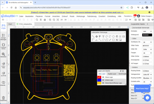
Das Hintergrundbild also quasi den "Wecker" habe ich mir recht günstig bei Etsy.com gekauft und somit sogar noch einen anderen Creator mit diesem Projekt unterstützt ;).
Ausblick
Als nächstes möchte ich dieses Projekt, wie bereits erwähnt, für das Jugendfreizeitzentrum Schöningen umsetzen. Besonders spannend daran ist, dass die Teilnehmer nicht nur das Löten auf einer Platine erlernen, sondern auch erste Erfahrungen im Programmieren sammeln können. Zudem lässt sich der Code erweitern, um beispielsweise die aktuelle Uhrzeit aus dem Internet über einen NTP-Server auf der Segmentanzeige darzustellen. Der ESP32-C3 Mini eröffnet dabei viele weitere Möglichkeiten für kreative Erweiterungen. Read the full article
0 notes
Text
Buy nodemcu esp8266 cp2102 at Affordable Price in Ainow

The ESP8266 NodeMCU CP2102 board has ESP8266 which is a highly integrated chip designed for the needs of a new connected world. It offers a complete and self-contained Wi-Fi networking solution, allowing it to either host the application or to offload all Wi-Fi networking functions from another application processor. ESP8266 has powerful onboard processing and storage capabilities that allow it to be integrated with the sensors and other application specific devices through its GPIOs with minimal development up-front and minimal loading during runtime. Its high degree of on-chip integration allows for minimal external circuitry, and the entire solution, including the front-end module, is designed to occupy minimal PCB area. The ESP8266 NodeMCU CP2102 development board – a true plug-and-play solution for inexpensive projects using WiFi. The module arrives pre-flashed with NodeMCU firmware so they’re ready to go – just install your USB driver (below). ESP-12 Lua Nodemcu WIFI Dev Board Internet Of Things board contains a full ESP8266 WiFi module with all the GPIO broken out, a full USB-serial interface, and a power supply all on the one breadboard-friendly package. This board is pre-flashed with NodeMCU a Lua-based firmware for the ESP8266 which allows easy control via a neat scripting language Lua so you’re ready to go in just a few minutes. The ESP-12 Lua Nodemcu WIFI Dev Board Internet Of Things with ESP8266 is an all-in-one microcontroller WiFi platform that is very easy to use to create projects with WiFi and IoT (Internet of Things) applications. The board is based on the highly popular ESP8266 WiFi Module chip with the ESP-12 SMD footprint. This WiFi development board already embeds in its board all the necessary components for the ESP8266 (ESP-12E) to program and upload code. It has a built-in USB to serial chip upload codes, 3.3V regulator, and logic level converter circuit so you can immediately upload codes and connect your circuits.
0 notes
Text
Visit Quazrtz Components today to buy your 5V Relay Module! 🛒 This versatile module is essential for controlling high-voltage devices with low-voltage microcontrollers. Enjoy reliable performance and easy integration into your electronic projects. Don't miss out—grab yours now and take your DIY electronics to the next level!
1 note
·
View note
Video
youtube
Wifi projects with ESP-12F/ESP-12E -Module basic settings, #AT Commands ...
0 notes
Text
Discover the Power of Connectivity: ESP32S WIFI BLE Board-V1.0
Unleash the potential of your projects with the ESP32S WIFI BLE Board-V1.0, a versatile and robust solution designed to revolutionize the world of wireless communication. This development board is built around the powerful ESP-WROOM-32, a Wi-Fi+BT+BLE MCU module that brings a new dimension to your applications, from low-power sensor networks to complex tasks like voice encoding, music streaming, and MP3 decoding.
The ESP32S WIFI BLE Board-V1.0 empowers you to break free from limitations. With its comprehensive features and capabilities, it is the perfect choice for a wide range of applications. Embrace its prowess in low-power sensor networks or let it tackle high-demanding tasks with ease. The dual-core architecture, running at an impressive 160MHz, opens up new horizons, while an abundance of pins and peripherals ensures you're equipped to handle whatever comes your way.
One of the standout features of the ESP32S WIFI BLE Board-V1.0 is the integration of Bluetooth, Bluetooth LE, and Wi-Fi. This harmonious blend ensures that your projects are future-proof, capable of addressing a diverse array of applications. Utilizing Wi-Fi extends your physical reach and allows direct connectivity to the internet via a Wi-Fi router. Meanwhile, Bluetooth connectivity brings the convenience of connecting to smartphones and the versatility of broadcasting low-energy beacons for effortless detection.
With the ESP32 chip's sleep current clocking in at less than 5 µA, the ESP32S WIFI BLE Board-V1.0 is primed for battery-powered and wearable electronics applications. This means that your creations can operate longer on a single charge, offering enhanced efficiency and sustainability. The support for data rates of up to 150 Mbps and an impressive 22 dBm output power at the PA ensures unparalleled connectivity and an extended physical range.
Indulge in the industry-leading specifications and performance that the ESP32S WIFI BLE Board-V1.0 brings to the table. The fusion of electronic integration, range, power consumption, and connectivity sets new standards for wireless communication solutions. No matter the complexity of your projects, this board is engineered to exceed expectations, making it the ultimate choice for forward-thinking innovators.
Are you ready to embark on a journey of connectivity and innovation? Embrace the future with the ESP32S WIFI BLE Board-V1.0, where your possibilities are limitless, and your projects are poised for greatness. Elevate your creations and embrace the world of wireless communication like never before.
0 notes
Photo

Follow us @uglandindia Node MCU-CH340 Wireless Module NodeMcu (LoLin) WIFI Internet Of Things Development Board Based ESP8266 - CH340 ESP-12E Visit www.uglandindia.com Download our android app from Google play store UG Land India Shopping app Discount coupon - APP10 with 10% discount applicable on mobile app Discount coupons - UGLAND with 5% discount applicable to direct website #uglandindia #uglandapp #ugland #shopping #Robotics #packaging #Electronic #module #sensor #electronicitems #wifi #wireless #wifimodule #esp #esp8266 #esp32 #usb #usbserial #technique #technology #embedded #computer #integrated #bluetooth #arduinoproject #scienceproject #serialport #store #Electronicstore #shoppingapps https://www.instagram.com/p/B-kMMSbph7-/?igshid=1w0lyxhbl8czk
#uglandindia#uglandapp#ugland#shopping#robotics#packaging#electronic#module#sensor#electronicitems#wifi#wireless#wifimodule#esp#esp8266#esp32#usb#usbserial#technique#technology#embedded#computer#integrated#bluetooth#arduinoproject#scienceproject#serialport#store#electronicstore#shoppingapps
0 notes
Photo

Wifi Cam 2.0 by Jan Neumann Visualizes wifi signals in a 2D plane in near real-time. "The distance between the ESP modules is currently 26mm. This is enough to capture the standing wave at 2,4Ghz with a wavelength of 12,5cm. If we need more resolution, there is the option to take multiple frames from different locations (on the same plane)."
3 notes
·
View notes
Text
WIRELESS MODULE with BLE and WiFi – ESP32-C3-DevKitM-1 The ESP32-C3-DevKitM-1 from Campus Component is a low-power, cost-effective solution for IoT developers. It combines WiFi and Bluetooth LE connectivity in a compact design. Featuring robust security features and efficient processing capabilities, this board is suitable for smart home devices, health monitors, and industrial IoT systems. It supports Espressif’s ESP-IDF framework.
0 notes
Photo

BLACKSTOMP - OPEN SOURCE DIGITAL PEDAL PLATFORM
“After working for 11 months, finally I release the full source code and schematic diagram of Blackstomp.
Download the source code at github.com/hamuro80/blackstomp
Get the complete schematic diagram and the software programming manual at https://www.deeptronic.com/blackstomp/
For those who hate to write any codes, the library comes with some working examples: tap-tempo stereo (ping-pong) delay and stereo chorus. Just compile and run from Arduino IDE and have a fun!I have successfully use it to develop vocoder and polyphonic pitch shifter pedal. I bet you can build this pedal with less than $30 bill of materials! Build yourself and have a fun! (and make money of it!) Hahhaaa..”
“Blackstomp is a digital audio effect processor development platform based on ESP32-A1S module. Here are some of the feature’s highlights:
Stereo line or guitar input/output
Microphone input with programmable gain pre-amp
Potentiometer, switch, button, and rotary encoder interfaces
OLED display interfaceMIDI input/output interface
WiFi and Bluetooth connectivity24-Bit stereo codec with analog pass-through
Dual core Tensilica Xtensa LX-6 240 MHz 32-bit processor with single precision FPU (floating point unit)
C++ library for fast development with Arduino IDE and ESP-IDF development tool chains.
The platform consists of hardware and software to implement digital effect pedal/stompbox. The hardware is designed for the simplicity and cost effectivity, while the software is designed to ease and speed up the application development.
s. more arduino and other programmable projects
cred: facebook.com/Hasan Murod
12 notes
·
View notes
Text
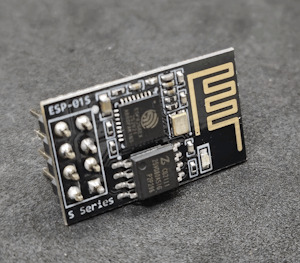
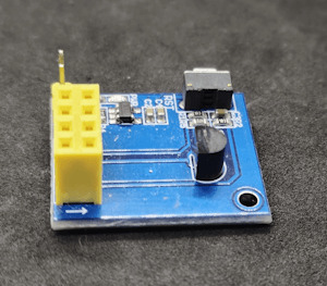
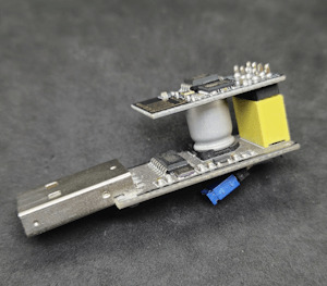
ESP-01S Temperatursensorshield DS18B20 Teil 2: Webseite mit Sensordaten erweitern

In diesem zweiten Teil möchte ich speziell darauf eingehen, wie du eine kleine Webseite für den ESP-01S mit dem Temperatursensor DS18B20 erstellen kannst. https://youtu.be/SeniGF1OMT8 Den ersten Teil zu diesem Beitrag findest du unter Arduino Lektion 81: ESP-01S Temperatursensorshield DS18B20 in diesem Beitrag hatte ich dir gezeigt, wie die Daten in einem JSON ausgeben werden können. Die Anzeige der Daten auf einer Webseite ist aber auch nicht viel schwerer, was du gleich erfahren wirst.

Was wird für dieses kleine Projekt benötigt?
Du benötigst nachfolgende Module zum Programmieren und messen der Sensordaten: - einen ESP-01S*, - ein Modul mit Temperatursensor DS18B20*, - ein USB-Programmer* für den ESP-01S, - ein Jumper - Universal Netzteil* Zusätzlich benötigst du noch ein Netzteil, welches eine Spannung von 3,7V bis max. 12V liefert. Wobei ich meines auf 4V einstelle. Hinweis von mir: Die mit einem Sternchen (*) markierten Links sind Affiliate-Links. Wenn du über diese Links einkaufst, erhalte ich eine kleine Provision, die dazu beiträgt, diesen Blog zu unterstützen. Der Preis für dich bleibt dabei unverändert. Vielen Dank für deine Unterstützung!
Programmieren einer Webseite mit Sensordaten des DS18B20 am ESP-01S in der Arduino IDE
Aus dem ersten Beitrag entnehme ich das kleine Beispiel mit der Ausgabe als JSON und forme diese einfach als HTML Seite um.
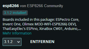
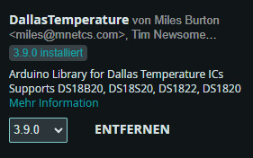
Programm - Anzeige der Sensordaten eines DS18B20 am ESP-01S auf einer WebseiteHerunterladen Schritt 1 - Import der benötigten Bibliotheken Für den Mikrocontroller ESP-01S benötigen wir zusätzlich einen Boardtreiber. Diesen können wir installieren wenn wir zuvor die nachfolgende Adresse den zusätzlichen Boardverwalter URLs hinzufügen. https://arduino.esp8266.com/stable/package_esp8266com_index.json Des Weiteren benötigen wir noch die Bibliothek DallasTemperature von Miles Burton.
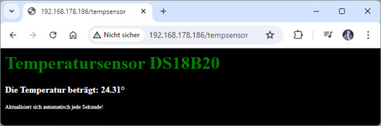
#include #include #include #include "secrets.h" Zusätzlich erzeuge ich die Datei secrects.h in welcher ich die Verbindungsdaten (SSID & Passwort) zum lokalen WLAN ablege. #define SSID "xxx" #define PASSWORD "yyy" Schritt 2 - aufbauen einer WiFi Verbindung zum lokalen WLAN Im zweiten Schritt bauen wir die WiFi Verbindung zum lokalen WLAN auf. Auch wenn der Mikrocontroller hinterher die Daten über die serielle Schnittstelle nicht mehr anzeigen kann, gebe ich im Code trotzdem die IP-Adresse aus. Jeder Router sollte den verbundenen Geräten immer dieselbe IP-Adresse vergeben, somit können wir zunächst im ersten Durchlauf ohne den Sensor die IP-Adresse auf dem seriellen Monitor ablesen können. const char* ssid = SSID; //SSID aus dem Router const char* password = PASSWORD; //Passwort für den Zugang zum WLAN ESP8266WebServer server(80); //Port auf welchem der Server laufen soll. void setup() { Serial.begin(9600); delay(10); //10ms. Warten damit die Seriele Kommunikation aufgebaut wurde. WiFi.begin(ssid, password); //Initialisieren der Wifi Verbindung. Serial.print("Aufbau der Verbindung zu "); Serial.println(SSID); while (WiFi.status() != WL_CONNECTED) { //Warten bis die Verbindung aufgebaut wurde. Serial.print("."); delay(500); } Serial.println(); IPAddress ip = WiFi.localIP(); Serial.print("IP-Adresse: "); Serial.println(ip); server.on("/tempsensor", callTempsensor); server.begin(); // Starten des Servers. } Schritt 3 - Erstellen einer kleinen Webseite für die Sensordaten Die kleine Webseite verfügt lediglich über eine Überschrift und zwei Paragrafen, in welche zum einen die Temperatur und zum anderen ein Hinweistext enthalten ist. void callTempsensor() { sensor.requestTemperatures(); String celsiusValue = String(sensor.getTempCByIndex(0)); String webseite = ""; webseite += ""; webseite += ""; webseite += "
Temperatursensor DS18B20
"; webseite += " Die Temperatur beträgt: {temp}°"; webseite += " Aktualisiert sich automatisch jede Sekunde!"; webseite += ""; server.send(200, "text/html", webseite); } Der CSS Stylesheet ist im Header -Bereich hinterlegt und lässt sich dort sehr einfach erweitern. webseite += ""; Zum Schluss wird der Platzhalter {temp} innerhalb des Strings mit dem Temperaturwert ersetzt. webseite.replace("{temp}", celsiusValue); fertiges Programm Nachfolgend das fertige Programm zum Anzeigen der Sensorwerte auf einer Webseite am ESP-01S.
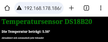
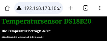
Zu einem Test habe ich das ganze mal in den Tiefkühlschrank gepackt und es werden hier auch die Minusgrade angezeigt. #include #include #include #include "secrets.h" #define ONE_WIRE_BUS 2 //Sensor DS18B20 am digitalen Pin 2 OneWire oneWire(ONE_WIRE_BUS); // //Übergabe der OnewWire Referenz zum kommunizieren mit dem Sensor. DallasTemperature sensor(&oneWire); const char* ssid = SSID; //SSID aus dem Router const char* password = PASSWORD; //Passwort für den Zugang zum WLAN ESP8266WebServer server(80); //Port auf welchem der Server laufen soll. void setup() { Serial.begin(9600); delay(10); //10ms. Warten damit die Seriele Kommunikation aufgebaut wurde. WiFi.begin(ssid, password); //Initialisieren der Wifi Verbindung. Serial.print("Aufbau der Verbindung zu "); Serial.println(SSID); while (WiFi.status() != WL_CONNECTED) { //Warten bis die Verbindung aufgebaut wurde. Serial.print("."); delay(500); } Serial.println(); IPAddress ip = WiFi.localIP(); Serial.print("IP-Adresse: "); Serial.println(ip); server.on("/tempsensor", callTempsensor); server.begin(); // Starten des Servers. sensor.begin(); //Starten der Kommunikation mit dem Sensor } void loop() { server.handleClient(); } void callTempsensor() { sensor.requestTemperatures(); String celsiusValue = String(sensor.getTempCByIndex(0)); String webseite = ""; webseite += ""; webseite += ""; webseite += "
Temperatursensor DS18B20
"; webseite += " Die Temperatur beträgt: {temp}°"; webseite += " Aktualisiert sich automatisch jede Sekunde!"; webseite += ""; webseite.replace("{temp}", celsiusValue); server.send(200, "text/html", webseite); } Read the full article
0 notes
Text

Introducing the latest version of the NodeMcu ESP8266 CH340 Module – a cutting-edge, budget-friendly WiFi technology. This advanced board utilizes modern, high-level LUA based technology and offers an all-in-one design, making it incredibly easy to integrate into your current Arduino projects or any development board with available I/O pins.
Utilizing modern Internet development tools, like Node.js, can effectively accelerate the implementation of your ideas with the assistance of the built-in API provided by NodeMCU. Based on ESP8266 technology, NodeMCU harnesses a wealth of online resources to further enhance its capabilities.
The NodeMCU ESP8266 CH340 Module is equipped with ESP-12 based serial WiFi integration, allowing for easy access to GPIO, PWM, ADC, I2C, and 1-WIRE resources. It also features a built-in USB-TTL serial using the dependable CH340 for superior stability on all compatible platforms. Additionally, this wifi-module is one of the most cost-effective options currently available in the market. Its latest version is known as V3 or Version3. In this tutorial, we will provide instructions to connect any version of ESP8266 NodeMcu (V1, V2, or V3).
Hardware IO similar to Arduino – An advanced API for easily configuring and manipulating hardware, reducing repetitive tasks. Write code in Lua script, just like with Arduino but in a more interactive manner.
The Event-driven API for network applications in Nodejs style enables developers to easily write code for a compact 5mm5mm sized MCU. This greatly accelerates the development process for IOT applications.
The ESP8266 Development Kit combines GPIO, PWM, IIC, 1-Wire, and ADC on a single board. By using the NodeMCU Firmware, it allows for quick and efficient development.
The NodeMcu is a useful tool for creating IoT prototypes. It is an open-source firmware and development kit that allows you to write Lua scripts with ease. This Development Kit is built on the ESP8266 platform and includes integrated features such as GPIO, PWM, IIC, 1-Wire, and ADC, all conveniently housed on one board.
Attributes of NodeMcu ESP8266 CH340 Module are:
Utilizes CH340G in place of CP2102.
The standard for wireless technology, specifically 802.11 b/g/n, eliminates the need for cables.
The WiFi operates at 2.4GHz and offers WPA/WPA2 security mode.
Provide assistance for the three available operating modes: STA, AP, and STA AP.
The TCP/IP protocol stack is integrated to facilitate the handling of multiple connections from TCP Clients (up to a maximum of 5).
The data communication interface supports UART and GPIO.
OTA, or remote firmware upgrade, is a quick and efficient way to update your device’s firmware without having to physically connect it to another device.
Assist the enhancement of Smart Link Smart Networking.
The IO Pin is an integral part of ESP8266.
There is no need to download the reset function.
An excellent toolkit for enhancing ESP8266 capabilities.
The WI-FI with the most affordable price.
For hardware IO compatible with Arduino.
Maximize efficiency in developing your IOT applications.
This product boasts a range of impressive features, including its open-source capability, interactivity, programmability, affordability, user-friendly design, intelligent functions, and WI-FI connectivity.
The integrated WI-FI MCU ESP8266 development kit offers effortless prototyping capabilities.
Our platform offers the most cost-effective solution for developing IoT applications.
NodeMCU ESP8266 CH340 Module features a built-in USB-TTL serial port, equipped with the highly dependable industrial-grade CH340G chip, ensuring unrivaled stability across all compatible platforms.
The Advanced API offers hardware IO capabilities that greatly minimize the need for repetitive tasks involved in setting up and managing hardware.
The network application’s event-driven API enables developers to write Nodejs-style code for a compact 5mm*5mm MCU.
0 notes
Photo

* 🇧🇷 Placa DIY para Prototipagem com o módulo ESP32. Todos os pinos disponíveis, fonte embarcada, Led ON, 5v é 3,3V ‐------------------------- www.projetoseletronicos.com youtube.com/ProjetosEletronicos -------------------------- 🇺🇸 DIY board for Prototyping with ESP32 module. All available pins, embedded source, LED ON, 5v is 3.3V -------------------------- #esp32 #esp #esp8266 #iot #internet #web #wifi #bluetooth #board #desenvolvimento #protótipo #prototipagem #eletronica #eletrônica #maker #diy #geek #walproj #projetosmaker #projetoseletronicos #hardware #software #firmware (em Projetos Eletronicos) https://www.instagram.com/p/CSzJ4Rurhqt/?utm_medium=tumblr
#esp32#esp#esp8266#iot#internet#web#wifi#bluetooth#board#desenvolvimento#protótipo#prototipagem#eletronica#eletrônica#maker#diy#geek#walproj#projetosmaker#projetoseletronicos#hardware#software#firmware
1 note
·
View note
Photo


#FLEXBALL
- a Hundred Pixel Flexible PCB Ball With WiFi designed by @maker.moekoe Flexball is based on a flexible PCB which is equipped with 100 WS2812 2020 addressable LEDs. It is controlled by an ESP8285-01f - the smallest ESP based module by Espressif. Additionally it has an ADXL345 accelerometer sensor on board.
.
- 15% off for Flex PCB (FPC) order.
3 notes
·
View notes