#iknowvations
Explore tagged Tumblr posts
Visit Tumblr Blog
Explore Tumblr blogs with no restrictions, modern design and the best experience.
Last Seen Tumblr Blogs


Fun Fact
Users from the US are the majority of Tumblr visitors.
Link
Temperature sensor plays a very important part in home & industrial automation fields. Today we will understand the basic technologies of temperature sensor
0 notes
Link
BMP 280 is a digital absolute barometric pressure sensor from Bosch Sensortec. This sensor is especially designed for mobile applications where small dimension and low power consumption is very important. Today we will see what exactly BMP 280 pressure sensor is all about and how we can use it in our various applications including application with Arduino.
0 notes
Link
DRV8825 Stepper motor driver is very useful module to drive any stepper motor. Learn how DRV8825 Stepper motor driver with Arduino tutorial to understand it
0 notes
Link
Today we will have a look at usb io board range from iknowvations that you can use for your projects depending upon your requirement. They provide not only digital and analog input output channels but also some of the usb io board have on board relays to make any electrical thing On or OFF.
0 notes
Link
USB relay board is a very useful board if you are considering dwelling yourself in making some home automation projects. To make any computer based automation projects, you need some kind of communication between your pc and the card to the board that is handling the input & output part.
Today we will see some of the projects that you can make using usb relay boards. For these projects, we will be considering two very good usb relay boards – iU-2RD and iU-4RD from iknowvations.
0 notes
Link
UIO-HMI-24 Digital Inputs/Outputs & DAQ board with
39 channels and USB/Bluetooth/RF connectivity ( depending upon different models).
Welcome to the world of Computer Automation. This usb io Board – UIO-HMI-24 is a perfect companion for all your computer automation projects where you require large number of I/Os as well as DAQ capability.
0 notes
Link
USB io 252 channel card UIO-369
USB io card is very useful for computer based automation requirements. UIO-369 card boasts up to 252 digital input /output channels. This card also is having ADC channels for measuring analog values.
0 notes
Text
New Post has been published on iknowvations
New Post has been published on https://iknowvations.in/sensors/temperature-sensor-and-its-fundamentals/
Temperature sensor and its fundamentals

Temperature sensor is used to measure temperature of any body or surface.Temperature plays a very important part in our day to day life. Any increase or decrease in temperature affects our daily routine. Even our body maintains our body temperature at 37 degree Celsius. Any deviation from this means there is something wrong in our body.
Same way in other fields like Industry, Agriculture, consumer electronics, cooking etc temperature plays a very important role. Monitoring and controlling this temperature not only helps us to save from dangerous situation but also provides means to gain maximum benefit from the situation.
Today we will look at how we can monitor and control temperature and various kind of sensors with which we can measure any temperature.
Temperature sensor technologies can broadly divided into four sections –
IC sensor
Thermistor
RTD
Thermocouple
Following table shows various aspects of each temperature sensor technologiy briefly.

Now let us see each technology in some detail –
IC Temperature sensor –
IC temperature sensors rely on predictive temperature dependence of a silicon band gap. As shown in following figure, the precision current sources the internal forward biased P-N junction with the resulting base-to-emitter voltage change ( delta VBE) that corresponds to the device temperature.

Because of predictable behavior of silicon, ICs offer high linearity and accuracy ( up to 0.1 degree C) across a wide temperature range. As sensors are made from silicon, they can also integrate system functionality such as analog-to-digital converters ( ADCs) or comparators that ultimately reduce system complexity and offer overall smaller footprint. This helps greatly to integrate them with latest microcontrollers and other electronics systems.

Various kinds of IC temperature sensors
Thermistor Temperature Sensor
Thermistors are passive components, with a resistance greatly dependent upon temperature. Thermistors are of two kinds – Positive Temperature Coefficient ( PTC) type and Negative Temperature Coefficient ( NTC) type.
Thermistors come in varity of packages but a typical implemention requires some additional parts also. While PTC thermistors offer linearity, NTC thermistors on the other hand are non-linear which results in increased calibration costs and software overhead.
The following figure shows typical implementation of thermistor.

Though cheap, these kind of implementation suffers from low level of accuracy because of various factors like – NTC tolerance, the temperature drift of bias resistor, quantization errors of ADCs, linearization errors inherent to NTCs etcs.

Various kinds of thermistor temperature sensors
RTD Temperature Sensor
Resistance Temperature Detectors – popularly known as RTDs are temperature sensors made of pure material like platinum, nickel or copper with a highly predictable resistance – temperature relationship.
Platinum RTDs are generally highly accurate and very linear across wide temperature range upto 600 degree C.
Following figure show a typical implementation of RTD sensor.

As the implementation of such sensor higher number of components, the overall size increases compared to other solutions. It also involves complex circuitry. RTDs require callibration during manufacturing and also annual calibration in the field.
While designing a system with RTDs, we have to keep in mind some factors like – RTD tolerance, self-heating, ADC quantization errors and references.

Typical Pt-100 RTD temperature sensor
Thermocouple Temperature Sensor –
Thermocouples are made of two different electrical conductors that form electrical junction at different temperatures. A thermocouple produces a temperature dependent voltage as a result of the thermoelectric Seeback effect. This voltage is directly proptional to the difference in temperature between the hot junction and cold junction.
So to measure the temperature of any surface ( also refered as Hot junction if you use thermocouple to measure temperature ), you should know the temperature of cold junction. Here the accuracy is limited by the fact that there are two systems that have separate tolerances and capabilities interacting with each other.
Following figure shows a typical CJC implementation with a thermocouple and an external sensor to determine the hot junction temperature.

Following picture shows various kind of thermocouples available in market.

Various kinds of thermocouple temperature sensors
Thus we have seen, the main four kind of temperature sensors. In coming days we will see how we can practically measure temperature using microcontrollers and also using Arduino board.
For further reading please refer informative ebook published by Texas Instruments. Many figures shown above are quoted from this very useful publication.
If you have any query, do contact our support team at support (at) iknowvations.in
0 notes
Text
New Post has been published on iknowvations
New Post has been published on https://iknowvations.in/arduino/drv8825-stepper-motor-driver-with-arduino-tutorial/
DRV8825 stepper motor driver with Arduino tutorial

The DRV8825 is a complete microstepping motor driver IC with built-in translator driving any stepper motor very easily . DRV8825 stepper motor driver is developed by Texas Instruments to help any one who wants to drive various stepper motor in their project.
Stepper motor is widely used for CNC and other automatic machinery projects. With the help of this DRV8825 stepper motor driver module, you can drive any stepper motor with just help of two pins of any microcontroller.
Today we will see in detail how this DRV8825 stepper motor driver can be interfaced with very popular Arduino board.
Features and Benefits of DRV8825 stepper motor driver
• PWM Microstepping Stepper Motor Driver – Built-In Microstepping Indexer – Up to 1/32 Microstepping • Multiple Decay Modes – Mixed Decay – Slow Decay – Fast Decay • 8.2-V to 45-V Operating Supply Voltage Range • 2.5-A Maximum Drive Current at 24 V TA = 25°C • Simple STEP/DIR Interface • Low Current Sleep Mode • Built-In 3.3-V Reference Output • Small Package and Footprint • Protection Features pin. – Overcurrent Protection (OCP) – Thermal Shutdown (TSD) – VM Undervoltage Lockout (UVLO) – Fault Condition Indication Pin (nFAULT)
DRV8825 Stepper motor driver module
As this IC comes in 28 pin HTSSOP package, it is little bit difficult for hobbyist to use this IC. So this module with all necessary components and connections becomes very easy to use in our projects.

DRV8825 Stepper motor driver module

DRV8825 Stepper motor driver module from below

DRV8825 Stepper motor driver module with heatsink
Interfacing DRV8825 stepper motor driver with microcontroller
Now, let us see how this module can be connected with any microcontroller.

DRV8825 connection detail
Let us explore now how this module functions with its various pins.
Power connection –
The module can be powered by DC supply up to 45 V and can handle up to 2.5 Amps current at 24 V. At 45 V the current rating is up to 2.2 Amps. These pins are highlighted in following pic. Generally the voltage will be between 8 and 45 Volt DC.
It is recommended to place a bulk power supply capacitor like 100 mfd near to power supply pins to smooth out current surges during driving of a stepper motor.
Please see that your power supply is rated at least 30% more than the maximum current that can be supplied to your stepper motor. Consult the manufacturer’s datasheet for this value.

Power pins of DRV8825 Stepper motor driver module
Stepper motor connection
Each bipolar stepper motor generally has 4 connection wires that connects to two internal windings of the motor. For example the following figure shows a typical NEMA 17 stepper motor.

NEMA 17 Stepper motor.
A typical bipolar stepper motor has following specifications –

Stepper motor specifications
Following figure shows the connection diagram of a stepper motor and also its working principle.

Stepper motor connection information
The stepper motor has to be connected to the DRV8825 Stepper motor driver module as follows.

Ok. After understanding the stepper motor connections, let us see how the power to DRV8825 stepper motor driver module is supplied.
Logic power supply
DRV8825 uses the motor power supply to power itself so unlike A4988 stepper motor IC , no other external power has to be applied. Only Gnd of the logic supply has to be provided as shown below.

After learning how the DRV8825 stepper motor driver can be connected to stepper motor, let us see how the motor can be controlled . This is done by properly handling the left hand side pins of the module.
Stepper motor control
Following pins show the most important part of the module as far as controlling the stepper motor is concerned – the Direction pin and Step pin.

Power control
Now let us understand power controlling pins. By this pins you can control the power to the module.

Fifth pin is Reset pin. It is also active low. By pulsing this pin low, you can place the stepper motor in Home position.
Sixth pin is Sleep pin. It is active low. By making this pin low makes this module sleep and the thus the power consumption can be reduced at lowest level.
Step selection
Most of the stepper motor has step angle of 1.8 degree. That means if you turn it for one step, the axis of the motor will turn 1.8 degree either clockwise or anticlockwise depending upon voltage level at Direction pin.
So for turning of one complete circle or one round will require such 200 steps. That means if you supply 200 pulses to the Step pin, the axis of motor will turn one full circle.
Now what if we want to turn the axis little bit finer… may be at 0.9 degree per step or may be half of that ? Fortunately , you can do it. Yes, the module can help you to have 1/2 , 1/4, 1/8 , 1/16 and 1/32 steps per one pulse input.
It is called microstepping and it is a rather complex process energizing the coils with proper current levels. But by using this module it becomes very easy to choose how much steps you want stepper motor to have one revolution.
Just choose the appropriate pins and there you have it !

By setting appropriate logic levels, you can choose the size of one step or in other way – you can choose number of total steps for one complete revolution. It is as under –
All these three pins are pulled internally low, so if you keep these pins disconnected or floating, the step resolution will be 1 and total steps per revolution will be 200.

The final pin is Enable pin. This pin is also active low. It is internally pulled low so by default. The Enable pin is used to control the output drivers and enable/disable operation of the indexer. When Enable pin is low, the output H-bridges are enabled, and rising edges on the STEP pin are recognized. When Enable is high, the H-bridges are disabled, the outputs are in a high-impedance state, and the STEP input is ignored.
There is also a Fault output pin, which becomes low whenever the H-bridge is disabled due to over current protection or thermal shutdown. By monitoring this pin, we can have a feedback of any fault occurring during operation of stepper motor driving.

So now you know properties of each pin and how you can utilize them for controlling of any stepper motor.
Current setting
Let us take one final step to start using this DRV8825 Stepper motor driver module.
Torque capacity of each type of stepper motor is different depending upon their construction. This determines how much maximum load they can turn per revolution. Which, in turn depends on how much current can be applied to each of the coil – also called rated current of the motor.
DRV8825 stepper motor driver module has one preset provided to set this maximum current value that can be applied to connected stepper motor.

As per datasheet of DRV8825 IC –
The current through the motor windings is regulated by a fixed-frequency PWM current regulation, or current chopping. When an H-bridge is enabled, current rises through the winding at a rate dependent on the DC voltage and inductance of the winding.
Once the current hits the current chopping threshold, the bridge disables the current until the beginning of the next PWM cycle. In stepping motors, current regulation is used to vary the current in the two windings in a semi-sinusoidal fashion to provide smooth motion.
The PWM chopping current is set by a comparator which compares the voltage across a current sense resistor connected to the xISEN pins, multiplied by a factor of 5, with a reference voltage.
The reference voltage is input from the xVREF pins. The full-scale (100%) chopping current is calculated as follows –
ICHOP = V (xREF) / 5 * R iSENSE Example: If a 0.25 ohm sense resistor is used and the VREFx pin is 2.5 V, the full-scale (100%) chopping current will be 2.5 V / (5 x 0.25 ohm) = 2 A. The reference voltage is scaled by an internal DAC that allows fractional stepping of a bipolar stepper motor.
So as far as our module is concerned, it uses 0.1 ohm resistors as sense resistor so to determine the VREF value we have to use following formula –
VREF = I ( max) * 0.5
One more fact, you have to keep in mind is that if you are using driver in full step mode, the current is limited to 70% of the maximum current limit, so accordingly you have to set the current limit almost 40% higher.
So for example if your stepper motor maximum current is 1A , then
VREF = 1 * 0.5 = 500mV
But if you are using full step mode, then
VREF = 1.4 * 0.5= 0.7 V
So after applying motor power supply, you can set the voltage at the preset at VREF as per your requirement with the help of multimeter and small screwdriver.
Interfacing DRV8825 stepper motor driver module with Arduino

Now that we have understood all the functionality of the module, let us see how we can use this DRV8825 stepper motor driver with Arduino.
Connect Arduino UNO to the driver module as follow –
Arduino pin Module pin +5 V 5 & 6 Gnd 9 – Gnd 4 8 – Direction 5 7 – Step
Now connect the 12 V power supply to module and also connect 4 pin connector to 4 pins of module ( 11,12,13 & 14 ) as shown in above figure.
We keep pins MS1, MS2 & MS3 pins floating so that the module will drive the stepper motor in full step mode. Also we keep Enable pin floating to enable the Driver outputs.
Arduino code for DRV8825 stepper motor driver
Following is the sketch of Arduino. Copy and upload to Arduino to see it functioning.
This sketch will rotate the stepper motor for one revolution clockwise and then one revolution counter clockwise. And this will go on repeating.
// Drive Stepper motor using A4988 stepper motor driver // for more info visit iknowvations.in // first define the pins const int DirPin = 4; // this pin defines direction CW or CCW const int StepPin = 5; // pulse this pin to move one step const int SPR = 200; // Steps per revolution void setup() // Make pins as Outputs pinMode(StepPin, OUTPUT); pinMode(DirPin, OUTPUT); void loop() // First let us rotate shaft clockwise digitalWrite(DirPin, HIGH); // defines the direction to clockwise // Pulse the step pin for(int x = 0; x < SPR; x++) digitalWrite(StepPin, HIGH); delayMicroseconds(1000); digitalWrite(StepPin, LOW); delayMicroseconds(1000); delay(1000); // Short delay of one second // Now rotate shaft counterclockwise digitalWrite(DirPin, LOW); // Again pulse the step pin for(int x = 0; x < SPR; x++) digitalWrite(StepPin, HIGH); delayMicroseconds(1000); digitalWrite(StepPin, LOW); delayMicroseconds(1000); delay(1000); // Short delay of one second
Code explanation
The above code is self explanatory.
First we define the pins. Make them as Output pins.
Then we decide whether to turn CC or CCW. Accordingly we make the Direction pin High or Low.
Then we pulse the Step pin as per our requirement of revolutions. For example in above example we want one revolution so we multiply that count with 200 ( steps per revolution ) . So we have to provide 1 * 200 = 200 pulses through Step pin to make one revolution.
That is it. It is very easy to drive stepper motors using DRV8825 stepper motor driver module.
Please note that you can also drive stepper motor using A4988 Stepper motor driver module. Interested ? go to A4988 Stepper motor driver with Arduino tutorial .
Try it and if you have any query, do comment below or you can also email to our support team at [email protected] to get answers.
Happy Stepping………………..
0 notes
Text
New Post has been published on iknowvations
New Post has been published on https://iknowvations.in/a4988-stepper-motor-driver-arduino-tutorial/
A4988 Stepper motor driver with Arduino tutorial

A4988 stepper motor driver module
The A4988 is a complete microstepping motor driver IC with built-in translator driving any stepper motor very easily . A4988 stepper motor driver is developed by Allegro Microsystems to help any one who wants to drive various stepper motor in their project.
Stepper motor is widely used for CNC and other automatic machinery projects. With the help of this A4988 stepper motor driver module, you can drive any stepper motor with just help of two pins of any microcontroller.
Today we will see in detail how this A4988 stepper motor driver can be interfaced with very popular Arduino board.
Features and Benefits of A4988 stepper motor driver
1. Low RDS(ON) outputs 2. Automatic current decay mode detection/selection 3. Mixed and Slow current decay modes 4. Synchronous rectification for low power dissipation 5. Internal UVLO 6. Crossover-current protection 7. 3.3 and 5 V compatible logic supply 8. Thermal shutdown circuitry 9. Short-to-ground protection 10. Shorted load protection 11. Five selectable step modes: full, 1/2, 1/4, 1/8, and 1/16
A4988 Steper motor driver module
As this IC comes in 28 pin QFN package, it is becomes little bit difficult for hobbyist to use this IC. So this module with all necessary components and connections becomes very easy to use in our projects.

A4988 stepper motor driver module top side

A4988 stepper motor driver module from below

stepper motor driver module with heatsink
Interfacing A4988 stepper motor driver with microcontroller
Now, let us see how this module can be connected with any microcontroller.

Let us explore now how this module functions with its various pins.
Power connection –
The module can be powered by DC supply up to 35 V and can handle up to 2A. These pins are highlighted in following pic. Generally the power will be between 8 and 35 Volt DC.
Please see that your power supply is rated at least 30% more than the maximum current that can be supplied to your stepper motor. Consult the manufacturer’s datasheet for this value.

Stepper motor connection
Each bipolar stepper motor generally has 4 connection wires that connects to two internal winding of the motor.

NEMA 17 stepper motor
A typical bipolar stepper motor has following specifications –

Stepper motor specifications
Following figure shows the connection diagram of a stepper motor and also its working principle.

Stepper motor connection diagram
The stepper motor has to be connected to the A4988 driver module as follows.

Ok. After understanding the stepper motor connections, let us see how the power to A4988 stepper motor driver module is supplied.
Logic power supply
5 V DC has to be supplied to following pins to power the module.

After learning how the A4988 stepper motor driver can be connected to stepper motor, let us see how the motor can be controlled . This is done by properly handling the left hand side pins of the module.
Stepper motor control
Following pins show the most important part of the module as far as controlling the stepper motor is concerned – the Direction pin and Step pin.

Power control
Now let us understand power controlling pins. By this pins you can control the power to the module.

Power controlling pins
First pin is Enable pin. This is active low – means this module can be enabled by keeping this pin at low level. Internally this pin is pulled low so you can leave this pin floating to keep it enabled. But making this pin High will disable this module.
Fifth pin is Reset pin. It is also active low. By pulsing this pin low, you can place the stepper motor in Home position.
Sixth pin is Sleep pin. It is active low. By making this pin low makes this module sleep and the thus the power consumption can be reduced at lowest level.
Step selection
Most of the stepper motor has step angle of 1.8 degree. That means if you turn it for one step, the axis of the motor will turn 1.8 degree either clockwise or anticlockwise depending upon voltage level at Direction pin.
So for turning of one complete circle or one round will require such 200 steps. That means if you supply 200 pulses to the Step pin, the axis of motor will turn one full circle.
Now what if we want to turn the axis little bit finer… may be at 0.9 degree per step or may be half of that ? Fortunately , you can do it. Yes, the module can help you to have 1/2 th , 1/4 th, 1/8 th and 1/16 th steps per one pulse input.
It is called microstepping and it is a rather complex process energizing the coils with proper current levels. But by using this module it becomes very easy to choose how much steps you want stepper motor to have one revolution.
Just choose the appropriate pins and there you have it !

Microstep size selection pins of A4988 stepper motor driver module
By setting appropriate logic levels, you can choose the size of one step or in other way – you can choose number of total steps for one complete revolution. It is as under –
All these three pins are pulled internally low, so if you keep these pins disconnected or floating, the step resolution will be 1 and total steps per revolution will be 200.
So now you know properties of each pin and how you can utilize them for controlling of any stepper motor.
Current setting
Let us take one final step to start using this A4988 Stepper motor driver module.
Torque capacity of each type of stepper motor is different depending upon their construction. This determines how much maximum load they can turn per revolution. Which, in turn depends on how much current can be applied to each of the coil – also called rated current of the motor.
A4988 stepper motor driver module has one preset provided to set this maximum current value that can be applied to connected stepper motor.

Preset to adjust the maximum current value
The voltage between the center point of this preset and the ground pin ( the pin number 9 ) of logic power supply ( VREF) , will determine the maximum current applied to the motor.
As per datasheet of A4988 IC,
The maximum value of current limiting is set by the selection of RSx and the voltage at the VREF pin. The transconductance function is approximated by the maximum value of current limiting, ITripMAX (A), which is set by ITripMAX = VREF / ( 8 * RS) where RS is the resistance of the sense resistor (?) and VREF is the input voltage on the REF pin (V).
So as far as our module is concerned, it uses 0.1 ohm resistors as sense resistor so to determine the VREF value we have to use following formula –
VREF = I ( max) * 0.8
One more fact, you have to keep in mind is that if you are using driver in full step mode, the current is limited to 70% of the maximum current limit, so accordingly you have to set the current limit almost 40% higher.
So for example if your stepper motor maximum current is 1A , then
VREF = 1 * 0.8 = 800mV
But if you are using full step mode, then
VREF = 1.4 * 0.8 = 1.12 V
So after applying 5 V to logic power supply, you can set the voltage at the preset at VREF as per your requirement with the help of multimeter and small screwdriver.
Interfacing A4988 stepper motor driver module with Arduino

A4899 Stepper motor driver with Arduino
Now that we have understood all the functionality of the module, let us see how we can use this A4988 stepper motor driver with Arduino.
Connect Arduino UNO to the driver module as follow –
Arduino pin Module pin +5V 10 Digital supply Gnd 9 Gnd 4 8 Direction 5 7 Step
Also connect 5th & 6th pin of module to each other. This will prevent the module not to go to Sleep mode.
Now connect the 12 V power supply to module and also connect 4 pin connector to 4 pins of module ( 11,12,13 & 14 ) as shown in above figure.
We keep pins MS1, MS2 & MS3 pins floating so that the module will drive the stepper motor in full step mode.
Arduino code
Following is the sketch of Arduino. Copy and upload to Arduino to see it functioning.
This sketch will rotate the stepper motor for one revolution clockwise and then one revolution counter clockwise. And this will go on repeating.
// Drive Stepper motor using A4988 stepper motor driver // for more info visit iknowvations.in // first define the pins const int DirPin = 4; // this pin defines direction CW or CCW const int StepPin = 5; // pulse this pin to move one step const int SPR = 200; // Steps per revolution void setup() // Make pins as Outputs pinMode(StepPin, OUTPUT); pinMode(DirPin, OUTPUT); void loop() // First let us rotate shaft clockwise digitalWrite(DirPin, HIGH); // defines the direction to clockwise // Pulse the step pin for(int x = 0; x < SPR; x++) digitalWrite(StepPin, HIGH); delayMicroseconds(1000); digitalWrite(StepPin, LOW); delayMicroseconds(1000); delay(1000); // Short delay of one second // Now rotate shaft counterclockwise digitalWrite(DirPin, LOW); // Again pulse the step pin for(int x = 0; x < SPR; x++) digitalWrite(StepPin, HIGH); delayMicroseconds(1000); digitalWrite(StepPin, LOW); delayMicroseconds(1000); delay(1000); // Short delay of one second
Code explanation
The above code is self explanatory.
First we define the pins. Make them as Output pins.
Then we decide whether to turn CC or CCW. Accordingly we make the Direction pin High or Low.
Then we pulse the Step pin as per our requirement of revolutions. For example in above example we want one revolution so we multiply that count with 200 ( steps per revolution ) . So we have to provide 1 * 200 = 200 pulses through Step pin to make one revolution.
That is it. It is very easy to drive stepper motors using A4988 stepper motor driver module.
Try it and if you have any query, do comment below or you can also email to our support team at [email protected] to get answers.
Happy Stepping………………..
0 notes
Link
How to set up usb relay board
0 notes
Text
New Post has been published on iknowvations.in : USB RS232 Relay Boards, Robotics,LED, Home Automation, Data Acquisition Systems
New Post has been published on https://iknowvations.in/arduino/ultrasonic-sensor-hc-sr04-arduino/
Ultrasonic sensor HC-SR04 with Arduino

Ultrasonic sensor HC-SR04 with Arduino
Ultrasonic sensor is very useful to detect the range of any object from its surface. Today we will have a look at ultrasonic sensor HC-SR-04, understand how it works and build a small project using it with Arduino.

We learn from nature and environment surrounding us. We know from early days that Bats use ultrasound – ultrasonic waves to locate their prey – a process called Echolocation.
As per Wikipedia
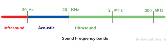
“Ultrasound is defined by the American National Standards Institute as “sound at frequencies greater than 20 kHz.” In air at atmospheric pressure ultrasonic waves have wavelengths of 1.9 cm or less.’
As per Wikipedia
” Bats can separate their calls and returning echoes by time. Bats that use this approach time their short calls to finish before echoes return. This is important because these bats contract their middle ear muscles when emitting a call, so they can avoid deafening themselves.
The time interval between the call and echo allows them to relax these muscles, so they can clearly hear the returning echo. The delay of the returning echoes provides the bat with the ability to estimate the range to their prey.”
We can use the same technique by using this ultrasonic sensor and find the distance of any object which is in front of the sensor.
The ultrasonic sensor HC-SR04

The above pic shows ultrasonic sensor module with 2 ultrasonic sensors, one of them is used as transmitter and the other as receiver.
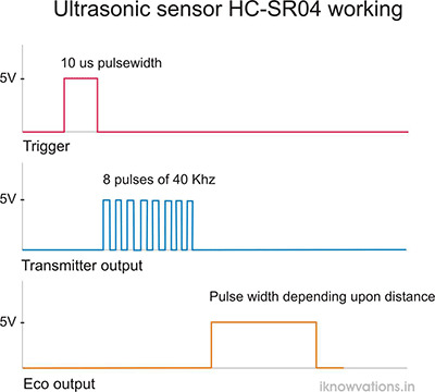
The below animation shows how this sensor works.
How to connect this ultrasonic sensor HC-SR-04 to Arduino.
As shown above there are 4 connecting pins of the sensor. One each is for power supply of 5 V and Ground. The other two are Trigger and Echo. Trigger pin is used to start a sound wave from transmitter and Echo pin is observed for the reflected wave. Once the sound wave is transmitted from the ultrasonic sensor, Echo pin is continuously monitored. The duration that the pin remains high depends upon the distance between the sensor and the object. Measuring the duration, the pin remains high will provide us the distance using the following formula.
distance = speed of sound * time taken /2
As per Wikipedia
” The speed of sound is the distance traveled per unit time by a sound wave as it propagates through an elastic medium. In dry air at 0 °C (32 °F), the speed of sound is 340.27 meters per second (1,116 ft/s; 1,225 km/h; 761 mph; 661 kn). At 20 °C (68 °F), the speed of sound is 343 meters per second (1,125 ft/s; 1,235 km/h; 767 mph; 667 kn), or a kilometer in 2.91 s or a mile in 4.69 s.”
For our calculation, we will consider the speed of sound at 340 meters per second. As we will be using this sensors for close range, we will convert it into 0.034 cm per micro second and use for calculating the distance for our project. The distance calculated has to be divided by 2 as the time taken is from sensor to the object and then the object to sensor, so it is a round trip for sound wave.
Also please bear in mind that the flat object which can reflect sound wave best will be easily detected while sharp & small objects or objects that deflect the sound waves in other direction than that of sensor, will not be able to be detected properly.
Connecting Arduino with ultrasonic sensor-
Connect the Arduino UNO and ultrasonic sensor as follows –
Arduino -> Sensor
5 V -> Vcc
Ground -> Ground
Pin 2 -> Trigger
Pin 3 -> Echo

Please note that you can connect any digital pin to Echo & Trigger pin of sensor provided you define them in arduino sketch.

The serial monitor output showing the distance in cms.

Following is the arduino sketch. Each step is explained. We are using pulseIn() command to measure the duration. The output will be shown every 500 ms.
/* * Ultrasonic Sensor HC-SR04 with Arduino * * by Jayprakash Shet * <a href="https://iknowvations.in" target="_blank" rel="noopener">iknowvations.in</a> */ // First we have to define the Trigeer & Echo pins const int trigPin = 2; const int echoPin = 3; String label = "Distance :"; String label1= " cms. "; // Now define the variables for distance & time long duration; int distance; // In the setup, we define the trigger pin as output pin and Echo pin, which has to be monitored for duration measurement. Also we start serial communication to monitor the distance calculated. void setup() pinMode(trigPin, OUTPUT); // Sets the trigPin as an Output pinMode(echoPin, INPUT); // Sets the echoPin as an Input Serial.begin(9600); // Starts the serial communication void loop() // First we have to clear the trigPin with some delay to stabilize the pin at low level digitalWrite(trigPin, LOW); delayMicroseconds(5); // Now sets the trigPin on HIGH state for 10 micro seconds which will make transuder to emit a burst digitalWrite(trigPin, HIGH); delayMicroseconds(10); digitalWrite(trigPin, LOW); // Read the echoPin, to get the duration in microseconds duration = pulseIn(echoPin, HIGH); // Now calculating the distance using the formula that will provide the distance in cm distance= duration*0.034/2; // Let us now print the distance on the Serial Monitor</pre> Serial.println(label + distance + label1); // put some delay delay(500); <pre>
If you have any questions or want some help regarding the ultrasonic sensor or arduino, do writ to us in comment section below or you can also shoot a mail to support@iknowvations for any kind of help.
0 notes
Text
New Post has been published on iknowvations.in : USB RS232 Relay Boards, Robotics,LED, Home Automation, Data Acquisition Systems
New Post has been published on https://iknowvations.in/usb/9-usb-relay-board-projects-can-make-easily/
9 USB relay board projects you can make easily

9 USB relay board projects you can make easily
USB relay board is a very useful board if you are considering dwelling yourself in making some home automation projects. To make any computer based automation projects, you need some kind of communication between your pc and the card to the board that is handling the input & output part.
Today we will see some of the projects that you can make using usb relay boards. For these projects, we will be considering two very good usb relay boards – iU-2RD and iU-4RD from iknowvations.

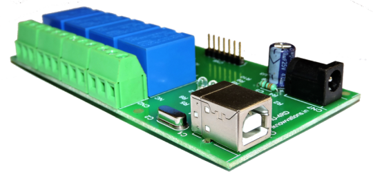
iU-4RD 4 channel usb relay board

iU-2RD-2 channel usb relay board
Please note that all the following projects using USB relay board also requires matching any higher level language ( VB, VC, C++, C# etc) based program in PC. Both the boards are having on board relays and analog input & digital input & output pins.
We can connect relays to any electrical equipment to make it ON or OFF while digital & analog inputs are used for connecting various kind of sensors.
Projects using USB Relay board –
1. Automatic light switch.

This project makes any light On or OFF depending upon certain conditions. For example you want your porch light to come ON when there is enough darkness in evening and be OFF when there is enough sunlight in morning.
You can connect LDR through register dividing network and monitor the voltage level through analog input pin of iU-2RD or iU-4RD. The program will monitor the input level which will be high or low depending upon the light falling on the sensor.
Based on this you can take decision if the lights have to be made ON or OFF. And so with the use of relays you can make the porch light ON or OFF.
You can also make your porch light or any other light ON or OFF based on the time of the day with the help of relay output.
2. Auto presence system.

Many times when we go out during vacation time, the house remains vacant. If any body observes the house, he / she can come to know that there is nobody in house and may become a target for burgle.
With the help of usb relay board and a small program you can make an auto presence system, which can fool outsider by making 2 or 3 lights of your house automatically ON or OFF during evening & night hours.
This will make anyone believe that there is somebody in house and it is not vacant. You can decide the day and the timings in the program and depending upon it the the lights connected with the usb relay board can be made ON or OFF.
3. Blinking LED through USB.

Well this is a very small & easy project – blinking LED. Though both of the usb relay board are having on board user LED which can be made ON or OFF simply by sending command LED1 to make it ON or LED0 to make it off. Making it ON or OFF repeatedly in program providing some suitable delay in between will make the user LED blink.
You can also connect LED to any digital output pin and blink it using output high & low commands.
4. Temperature controller.

You can connect any temperature sensor that provides analog output to the board’s analog input pin to monitor temperature. Using this property, you can make temperature controller yourself.
For example you want a system, where the temperature is maintained at 25 degree centigrade. Just connect any suitable temperature sensor like LM35 or similar to analog input pin. Monitor the analog output level in program and based on this you can make fan or Heater ON/OFF through on board relays.
5. Home alarm system.

Connect some magnetic switches & PIR sensors to digital inputs and a hooter to the relay output. Voila ! you have got a Home Alarm system. Yes, with the help of these few things and usb relay board, you can make a Home Alarm System yourself within no time.
The magnetic & PIR sensors will help you to monitor any intrusion through doors & windows and the hooter will make a big sound when any kind of intrusion is attempted.
6. Digital Water Meter.

Do you want to have an eye on your water usage ? Want to have an early warning when you cross a particular water consumption ? Then, this is a perfect evening project for you to make.
Grab yourself a water flow sensor. when you connect this flow sensor to your main water inlet line, you will get pulses at the sensor output which will be proportional to your water usage. Connect this to digital input of usb io board, write a small program monitoring the pulses input and there ! you have made a Digital water meter !
7. Aquarium controller.

The automation system of your aquarium will not only keep your fishes very happy but you also as it will relieve yourself of daily routines of feeding & maintaining of oxygen level & temperature of the water, feeding the fishes and keeping the water clean.
All of these can be done with the use of usb relay board and a small program in your PC. The temperature sensor can be connected to analog input of the board and the pump and the feeding system and be connected to the on board relays.
8. Auto sprinkler system.

Maintaining your garden requires proper care and your precious time. Many times, it is not possible to spend time in your garden due to various reasons like Not well, gone for vacation, out of the town, very busy in day to day work etc.
During these periods, if you are having a system that can take care of your garden, the garden will not suffer any damage due to non care. The usb relay board connected pump can water your garden at pre defined time regularly.
Not only this but you can also add soil moisture sensor to measure the moisture in garden soil and based on this it will water the garden.
So now keeping your garden lush green is a not a headache !
9.Decorative Light pattern generator.

There are many times when we decorate our home with many different colored lights & LED bulbs like Birthday parties, during Christmas and the festivals, wedding anniversaries etc.
How about adding some variations in lighting ? We are attracted to moving things much more than a steady thing. Moving light patterns will attract more to your guests rather than steady lights.
You can connect these lights through usb relay board relays and make them ON one by one adding some delays in between. This will create different light patterns as per your choice. This will not only be more attractive but you can have many unique patterns that your guests may not have seen any where else.
In coming days we will show exactly in detail, how all these projects can be made. So watch out this space regularly.
So go genius ! Grab a usb relay board & unleash your creativity ! And yes, we are there to help you in case you have any difficulty. just contact our support team at [email protected] and they will be more than happy to turn your idea into a successful project.
0 notes
Text
New Post has been published on iknowvations.in : USB RS232 Relay Boards, Robotics,LED, Home Automation, Data Acquisition Systems
New Post has been published on https://iknowvations.in/usb/usb-relay-board-set/
USB relay board - How to set up

USB relay board – How to set up
USB relay board uses usb port to make a mechanical relay ON or OFF. This way we can make any electrical equipment ON or OFF with the help of computer. This is very good for any kind of Home automation or Industrial automation projects.
Today we will see how to set up usb Relay Board – iU-2RD and usb Relay board – iU-4RD from Iknowvations.

Both of these boards are very useful for any kind of computer based automation systems. Theses boards are having not only on board relays to operate any kind of electrical equipment but also have digital & analog input & output pins on the board. This digital input and output pins help to do more with these boards.
With the help of these pins you can add mechanical switches, different kind of digital & analog sensors and can make a closed loop automation system. For example, if you want a system where the relays should be ON till a mechanical switch is pressed. This kind of system can be very easily done using this usb relay board.
Now, let us see how we can set up one of these usb relay board. This procedure is same for both the boards as they both employ same IC sets.
1. Download the installation file ( CH340 drivers) from our download section at https://iknowvations.in/downloads. at any convenient place and run the file with administrative rights. Follow the on screen instructions This will install necessary file into your computer.

2. Now when you plug in your iU-2RD board first time into computer, the computer will recognize it as a COM port based card and will assign a COM port to the card. This can be checked with the Device Manager tab in Control panel of your computer as shown below-

3. This confirms that the board is now active and connected with your computer. The power LED of the board will be ON and the board when first time gets power will respond with blinking of the User LED. The board has got dual power supply inputs. That is the board can be powered from USB connector as well as 12 V DC power connector. The only thing is that when you want to operate Relays, you have to power the board with 12 V DC power supply as the USB power will not be able to supply the power to operate the on board relays.
4. Now let us test the board. As the board shows up as COM port on your computer you can connect with the board with any serial monitor program like HyperTerminal or PUTTY.
5. Once the usb relay board – iU-2RD is connected to the computer, start the HyperTerminal with 9600 bauds, 8 bits, No parity and 1 stop bit as shown below.

6. You can communicate with the board with the set of commands. All commands are described in User Manual of these respective boards. Please note that all the commands that can be entered have to be in Capital. Please read the User Manual of iU-2RD before using this card. This can be downloaded from the download section at https://iknowvations.in/downloads/.
7. Now in HyperTerminal window type HELP and press enter key. The board will respond with the HELP menu as shown under –

8. You can play with board using various commands described in the User Manual. For example if you type LED1, the user LED on board will be ON. To make it off, type LED0 and press enter key. The LED will be off. Likewise you can turn ON the Relay1 by sending command RL11 and make it off by RL10 and so on. Please note that you have to use 12V DC power supply to operate the relays.
This shows how you can use this usb relay board with the help of HyperTerminal. Similarly, you can also use this board with your own programs built using higher level languages like VB, Delphi, VC, VC++, C# , Java etc. The program itself can operate the board by sending the proper commands through the assigned COM port.
This way usb relay board iU-2RD can be very useful in any kind of industrial , Consumer or Home automation kind of projects.
More information about our usb relay boards can be found at https://iknowvations.in/product-category/usb-relay/
In coming days, we will post many projects that you can build yourself using these usb relay boards. So what out this space regularly.
0 notes
Link
0 notes
Link
USB port is an important communication channel for PC as well as smartphone based automation projects. Though USB port does not have any Digital & analog I/Os, with the help of special boards like our iU-45D board,we can turn it into multiple digital & analog I/Os for controlling purpose.
Digital & analog I/Os – digital & analog input / outputs play very important role in any automation project. Automation means acquiring the data, processing it & making decision based on certain predefined rules. According to this, it will set outputs.
0 notes