#program esp8266 with arduino
Explore tagged Tumblr posts
Visit Tumblr Blog
Explore Tumblr blogs with no restrictions, modern design and the best experience.
Last Seen Tumblr Blogs


Fun Fact
Hackers stole 65M passwords from Tumblr in 2013.
Text
Understanding ESP32 Pin Configuration: A Developer's Guide
The ESP32 microcontroller has become a cornerstone of IoT development, thanks to its versatility and powerful features. One of the most crucial aspects of working with ESP32 is understanding its pin configuration and capabilities. Let's dive into the essential aspects of ESP32 pins that every developer should know.

GPIO Pins Overview
The ESP32 boasts up to 34 GPIO (General Purpose Input/Output) pins, but not all are available for use in most development boards. Some key points about ESP32 pins:
GPIO 6-11: Reserved for internal SPI flash connection
GPIO 34-39: Input-only pins with no internal pull-up/pull-down resistors
ADC Capabilities: Two 12-bit SAR ADCs, supporting 18 measurement channels
Touch Sensors: Up to 10 capacitive touch GPIOs
Special Function Pins
Several pins serve dual purposes or have specific functions:
Boot Mode Pins GPIO 0: Bootloader mode when pulled low during reset GPIO 2: Connected to on-board LED in many development boards
UART Pins GPIO 1 (TX) and GPIO 3 (RX): Default UART0 communication Often used for flashing and debugging
SPI Pins VSPI: GPIO 5 (CS), 18 (CLK), 19 (MISO), 23 (MOSI) HSPI: GPIO 14 (CLK), 12 (MISO), 13 (MOSI), 15 (CS)
Best Practices for Pin Usage
Strapping Pins Always check the strapping pin status before using GPIO 0, 2, 4, 5, 12, and 15. These pins may affect boot behavior if incorrectly configured.
Input-Only Pins When designing sensor interfaces, prefer GPIO 34-39 for analog inputs as they're input-only and less susceptible to noise.
Pull-up/Pull-down Configuration
ADC Usage ADC1: Can be used with Wi-Fi/Bluetooth active ADC2: Only available when Wi-Fi/Bluetooth is disabled
Common Pitfalls to Avoid
Don't use GPIO 6-11 in your projects as they're connected to the internal SPI flash.
Avoid using strapping pins for critical functions that can't be changed during boot.
Remember that GPIO 34-39 don't have internal pull-up/pull-down resistors.
Be cautious with voltage levels - ESP32 pins operate at 3.3V.
Conclusion
Understanding ESP32 pinout is fundamental for successful project development. By following these guidelines and best practices, you can avoid common issues and make the most of your ESP32's capabilities. Remember to always consult the official ESP32 technical reference manual for detailed specifications and updates.
#ESP32 #PinConfiguration #DevelopersGuide #Microcontrollers #EmbeddedSystems #IoT #Programming #Hardware #Electronics #Arduino #ESP32S2 #ESP32C3 #ESP32C2 #ESP32C6 #ESP32S3 #ESP32H2 #ESP32P1
#ESP32#microcontroller#pinconfiguration#GPIO#ADC#DAC#I2C#SPI#UART#PWM#analog#digital#input#output#microcontrollers#embeddedsystems#IoT#InternetOfThings#electronics#hardware#software#programming#development#Arduino#ESP8266#RaspberryPi#microcontrollerprogramming#embeddedprogramming#IoTdevelopment#electronicdesign
1 note
·
View note
Text
The ESP32 is a development board developed by Espressif systems. It can be programmed using Arduino IDE and ESP-IDF. It has higher processing power than ESP8266 but it is more costly and bigger in physical dimension than ESP8266. It has a built in Bluetooth module and CAN protocol and SRAM. It has 36 GPIO Pins with a CPU clock of 160MHz. It has 12-bit ADC onboard and supports CAN, UART, I2C and I2S. It can be used in prototyping IoT products, Low power Battery operated application, small range networking projects, and with the projects which require many Input Output Pins and Wi-Fi and Bluetooth connectivity.
6 notes
·
View notes
Text
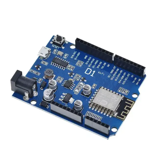
Wemos D1 Wifi Dev Board for Esp8266 IOT Module Online price is 10 units MOQ. Specification: Based on ESP-8266EX Compatible with Arduino,can be program by arduino ide. I/O Pin:11pcs Working Voltage:3.3V Input:7-24V Flash:4MB SRAM:32KB DRAM:80KB Clock Frequency:80MHz/160Mhz Network:802.11b/g/n Other development board you may interest: Interested with much more quantity,contact us to talk price.Know more about company site here. Read the full article
1 note
·
View note
Text
Getting Started with Embedded Systems Programming

Embedded systems programming is the backbone of modern electronics. From smartwatches to washing machines, embedded systems power the intelligent functions of countless everyday devices. This guide will introduce you to the basics of embedded programming, key tools, and how to begin building your own embedded applications.
What is an Embedded System?
An embedded system is a computer integrated into a larger system or device, performing dedicated functions. Unlike general-purpose computers, embedded systems are designed for specific tasks, often with constraints on power, memory, and processing.
Examples of Embedded Systems:
Microcontrollers in home appliances
Sensor-based devices (e.g., temperature sensors, motion detectors)
Medical equipment
Automotive control systems
IoT (Internet of Things) gadgets
Core Components of an Embedded System
Microcontroller or Microprocessor: The brain of the embedded system (e.g., Arduino, STM32, ESP32).
Memory: RAM and ROM to store instructions and data.
Input/Output Interfaces: Connects to sensors, displays, motors, and communication modules.
Software: Custom firmware developed for specific functions, typically in C or C++.
Popular Programming Languages
C: Most widely used due to its efficiency and low-level hardware access.
C++: Used when object-oriented design is required.
Assembly: For highly optimized or time-critical routines.
MicroPython: Python for microcontrollers (e.g., ESP8266, Micro:bit).
Getting Started with Embedded Programming
Select Your Platform:
Beginners: Arduino (easy setup, wide community support)
Advanced: STM32, Raspberry Pi Pico, ESP32
Set Up Your Development Environment:
Install IDEs like Arduino IDE, PlatformIO, STM32CubeIDE
Download necessary drivers and board support packages
Write and Upload Code: Create simple programs like blinking an LED, then expand to sensors, displays, and communication modules.
Example: Blink an LED with Arduino
void setup() { pinMode(13, OUTPUT); // Set pin 13 as output } void loop() { digitalWrite(13, HIGH); // Turn LED on delay(1000); // Wait for 1 second digitalWrite(13, LOW); // Turn LED off delay(1000); // Wait for 1 second }
Tools and Debugging
Serial Monitor: For real-time debugging and logging.
Oscilloscope & Logic Analyzer: For electrical signal inspection.
In-Circuit Debuggers: Like JTAG or ST-Link for low-level debugging.
Best Practices
Write modular and readable code.
Use debouncing for physical inputs like buttons.
Handle memory carefully to avoid overflows.
Optimize power usage in battery-powered devices.
Conclusion
Embedded systems programming is both fun and powerful, offering endless possibilities for innovation in hardware and software. Whether you’re building a home automation project or diving into the world of IoT, understanding the basics of embedded programming gives you the foundation to create smart, responsive devices.
0 notes
Text
Chatgpt computer communication design
Designing a computer circuit where two computers communicate with each other and "teach themselves" using an Arduino board involves a combination of hardware setup and software programming. Here’s a general guide to get you started:
1. Basic Concept
Two Computers (PCs or Microcontrollers): These are the two devices that will communicate and learn from each other. Each will run a program for self-learning.
Arduino Board: The Arduino will facilitate the communication between the two computers and control the process. It could also be part of the system performing calculations or simulations.
Communication Protocol: The two computers will need to communicate with each other. For simplicity, we can use serial communication (UART) or I2C with the Arduino acting as the intermediary.
2. Hardware Components
Arduino Board (e.g., Arduino Uno, Nano, or Mega)
Two Computers (PCs or other microcontrollers, like Raspberry Pi or other Arduino boards)
Communication Module: If you are using something like a Raspberry Pi or another microcontroller, you might need USB-to-Serial adapters or Bluetooth/Wi-Fi modules (e.g., ESP8266/ESP32, HC-05).
Power Supply: Proper power sources for the Arduino and computers.
Cables: USB, serial cables, or jumper wires for communication.
3. Circuit Design
Here is a high-level overview of the connections between the Arduino and the two computers.
Arduino and PC1 (Computer 1):
Connect the Arduino to PC1 via USB or UART communication pins (TX/RX pins if using serial).
Arduino and PC2 (Computer 2):
If you are using a second microcontroller (like another Arduino or a Raspberry Pi), connect them to the Arduino board using a communication protocol (e.g., I2C or UART).
The two computers could either communicate directly over a network (like Ethernet or Wi-Fi) or through serial communication.
For this example, let’s assume you are using UART for communication between the Arduino and both computers. You can use the TX/RX pins on the Arduino and connect them to the USB-to-Serial adapters connected to each computer.
4. Software Design
The software should allow the computers to "teach themselves," which likely means implementing some form of machine learning or pattern recognition. For simplicity, let’s outline how you could set up communication, with the learning part handled on the computers.
Arduino Code: The Arduino will act as the middleman for the communication. It will receive data from one computer, send it to the other, and also handle basic processing or simulation. It can be programmed to send responses or instructions back to the computers.
// Simple Arduino code for UART communication void setup() { Serial.begin(9600); // Start the serial communication at 9600 baud } void loop() { if (Serial.available()) { char incomingByte = Serial.read(); // Read incoming byte Serial.print("Received: "); Serial.println(incomingByte); // Send back the received byte } }
Computer 1 and Computer 2 Code: Each computer should run a program that will send data to the Arduino and receive responses. This could be a simple Python script or C++ program for serial communication.
Example Python Script: Here’s a basic Python script that can run on each computer. This script will send data to the Arduino and read the response back.import serial import time # Open serial port (make sure to change COM port for your system) ser = serial.Serial('COM3', 9600) # Change COM port as needed time.sleep(2) # Wait for the serial connection to initialize # Send data to Arduino ser.write(b'Hello Arduino!\n') # Read response while True: if ser.in_waiting > 0: response = ser.readline().decode('utf-8').strip() print(f"Arduino says: {response}") break ser.close()
This Python script could run on Computer 1, while a similar script runs on Computer 2. Both will send messages to the Arduino and receive feedback.
5. Self-Learning Simulation
To simulate the "self-teaching" aspect, each computer can use machine learning algorithms. You could start with something simple like linear regression or a decision tree. The computers could send random data points to each other and exchange feedback on whether the predictions made by each other are correct.
Computer 1 could generate a random dataset and send it to Computer 2.
Computer 2 processes the data, makes predictions, and sends the feedback back.
Computer 1 uses this feedback to adjust its learning algorithm (e.g., adjust weights in a simple linear regression model).
Example of a Simple Learning Process: Each computer could adjust its internal model based on the received feedback, similar to how a neural network or other machine learning models learn. The Arduino could be involved in simple processing tasks or sending acknowledgment signals when certain thresholds are reached (e.g., "success" or "failure").
6. Scaling Up
If you want to scale up the project to involve more complex learning or higher levels of interaction, you could use a more advanced platform such as a Raspberry Pi or ESP32/ESP8266 for networking and faster processing, where each computer uses a machine learning library (like TensorFlow Lite or scikit-learn).
7. Final Setup
Computer 1 and Computer 2 run machine learning algorithms that adjust based on feedback.
Arduino manages data flow between the computers and possibly performs basic learning tasks like adjusting variables or sending commands.
The entire system simulates a network where two computers are learning from each other.
This is a high-level overview, and there are many ways to implement it depending on the complexity of the communication and learning algorithm you want to achieve. Would you like to dive deeper into any specific area or need more detailed code for the project?
Creating two PCs from scratch using Arduino boards is an interesting challenge, but it's important to note that a full-fledged personal computer involves much more complexity than an Arduino is capable of. However, you can certainly simulate basic "PC-like" behavior using Arduino boards, where each "PC" would be a microcontroller (Arduino) with some level of functionality, communication, and processing.
High-Level Concept
Each Arduino board would act as a basic computing unit (like a simplified "PC"), running simple programs, processing input, and communicating with each other. While these "PCs" won't have the advanced features of a real computer (like an OS, GUI, or complex processing power), they can serve as learning devices or communication nodes in a network.
To make two PCs communicate with each other using an Arduino board, the Arduino acts as an intermediary. The Arduino will handle the communication between the two PCs, either via a serial connection (UART), I2C, or wireless communication (e.g., Bluetooth/Wi-Fi). Below is a guide on how to set up such a system:
1. Hardware Setup
Here, I'll describe a setup where two PCs communicate via an Arduino board using serial communication (UART). The Arduino will act as a mediator, forwarding messages between the two computers.
Components Needed:
Arduino board (e.g., Arduino Uno, Nano, Mega)
2 PCs (PC1 and PC2)
USB-to-Serial adapters (if using UART)
Jumper wires (if using direct communication between Arduino and PC)
Connections:
PC1 <-> Arduino: The first PC will communicate with the Arduino using its USB port (acting as a serial port).
PC2 <-> Arduino: The second PC will communicate via another USB-to-Serial adapter or possibly the second USB port of the Arduino (if the Arduino model supports multiple serial connections, e.g., Mega).
In simpler terms:
Arduino will be connected via USB to PC1.
PC2 will be connected to Arduino's serial pins (TX/RX) or using a USB-to-Serial adapter.
2. Arduino Code
The Arduino will need to read from one serial port (PC1) and forward the data to another serial port (PC2) and vice versa. The following is a simple Arduino sketch for this task.// Arduino code for mediating between two PCs void setup() { // Start serial communication with both computers Serial.begin(9600); // For communication with PC1 Serial1.begin(9600); // For communication with PC2 (if using Arduino Mega or another board with multiple serial ports) } void loop() { // Check if data is available from PC1 (connected to Serial) if (Serial.available() > 0) { char dataFromPC1 = Serial.read(); // Read data from PC1 Serial1.write(dataFromPC1); // Send data to PC2 (connected to Serial1) } // Check if data is available from PC2 (connected to Serial1) if (Serial1.available() > 0) { char dataFromPC2 = Serial1.read(); // Read data from PC2 Serial.write(dataFromPC2); // Send data to PC1 (connected to Serial) } }
Explanation of the Code:
Serial.begin(9600): Initializes communication with PC1.
Serial1.begin(9600): Initializes communication with PC2. (Note: Only available on boards with multiple UARTs like Arduino Mega, if using an Arduino Uno, you’ll need a USB-to-Serial adapter for PC2).
Serial.read(): Reads data from one serial port.
Serial.write(): Sends data to the other serial port.
3. Software on the PCs
On each of the two PCs, you will run a program that communicates with the Arduino via a serial connection. You can use Python to interface with the Arduino. Here’s a simple Python example that reads data from the Arduino and sends data back.
Python Code for PC1:
import serial import time # Connect to Arduino via serial port (Adjust the port name as needed) ser = serial.Serial('COM3', 9600) # Replace 'COM3' with your Arduino's port time.sleep(2) # Wait for the serial connection to establish # Send data to Arduino (which will forward to PC2) ser.write(b'Hello from PC1!\n') # Read data from Arduino (which is coming from PC2) while True: if ser.in_waiting > 0: response = ser.readline().decode('utf-8').strip() print(f"Received from PC2: {response}") break ser.close()
Python Code for PC2:
import serial import time # Connect to Arduino via serial port (Adjust the port name as needed) ser = serial.Serial('COM4', 9600) # Replace 'COM4' with your Arduino's port time.sleep(2) # Wait for the serial connection to establish # Read data from Arduino (which is coming from PC1) while True: if ser.in_waiting > 0: message = ser.readline().decode('utf-8').strip() print(f"Received from PC1: {message}") # Send data back to Arduino (which will forward to PC1) ser.write(b'Hello from PC2!\n') break ser.close()
4. Explanation of the PC Software:
Python serial library: Used to open a serial connection to the Arduino.
ser.write(): Sends data from PC1 or PC2 to the Arduino.
ser.readline(): Reads incoming data from the Arduino, which is forwarded from the other PC.
Time Delays: time.sleep(2) ensures that the serial connection is established before communication begins.
5. Communication Flow
PC1 sends a message (e.g., "Hello from PC1") to the Arduino.
The Arduino forwards the message to PC2.
PC2 receives the message, processes it, and sends a response back to the Arduino (e.g., "Hello from PC2").
The Arduino forwards the message back to PC1.
6. Adjusting for More Complex Setups
If you are using an Arduino Uno (which has only one serial port), you’ll need an additional USB-to-Serial adapter to handle communication with both PCs. Alternatively, you can use an Arduino Mega, which has multiple serial ports (like Serial, Serial1, Serial2, etc.).
For the Arduino Mega, you can use Serial for PC1 and Serial1 for PC2, as shown in the code above.
For PC2, you might need a USB-to-Serial adapter if you're not using an Arduino Mega.
7. Next Steps
To make the setup more advanced, you can:
Add error handling and retry mechanisms for more robust communication.
Implement data processing algorithms to simulate machine learning (e.g., a simple model for each PC that "learns" from the data it receives).
Use wireless communication like Bluetooth or Wi-Fi if you don't want to rely on USB connections.
Would you like to explore how to expand this further or add more complexity to the system? Let me know!
Here’s how you might approach creating two Arduino-based "PCs" from scratch:
1. Basic Requirements and Constraints
You’re working with Arduino boards, which are microcontrollers with limited processing power, memory, and storage compared to a real PC. The Arduino can run basic programs, perform calculations, and communicate with other devices, but it cannot run complex software like a PC.
To simulate PCs, you'll need:
Arduino microcontroller boards (e.g., Arduino Uno, Nano, Mega, etc.)
Inputs/outputs (e.g., buttons, LEDs, displays)
Communication method between the two Arduinos (e.g., UART serial, I2C, or even wireless)
Storage (limited, but can use EEPROM or SD card modules)
Basic display (e.g., an LCD or LED screen for output)
2. Building the Two "PCs" with Arduino
Each Arduino board will act as one "PC." Here’s how you can conceptualize the setup:
Arduino 1 (PC1): Will handle user input and perform computations.
Arduino 2 (PC2): Will also handle user input and perform computations. It will communicate with PC1 to share or exchange data.
The communication between the two PCs can be done using serial communication (UART) or I2C.
3. Basic Hardware Setup for Each PC
Each "PC" could have:
Buttons or switches to simulate input (e.g., user input or commands).
LCD or 7-segment display for output (or use an LED to indicate activity).
Communication interface to talk to the other PC (e.g., UART or I2C).
SD card or EEPROM to simulate storage.
Components Needed:
2 Arduino boards (e.g., Arduino Uno or Nano)
1 LCD display (16x2 or 20x4 for basic text output)
2 push buttons (to simulate input)
2 LEDs (to indicate some activity or status)
2 USB-to-Serial adapters (if using UART communication between PCs)
1 I2C or UART communication method
1 SD card module (optional for storage simulation)
4. Software Design for the "PCs"
Each Arduino PC will need a program to read inputs, perform some basic computation, and send/receive data to/from the other PC. Here’s a simple breakdown of the software for each Arduino:
Arduino PC1 (PC1 Sketch)
This sketch allows PC1 to process input (button presses), perform simple calculations, and send/receive data from PC2.#include <Wire.h> // For I2C communication (if using I2C) #include <LiquidCrystal_I2C.h> // For LCD display // Initialize the LCD (change pin numbers according to your setup) LiquidCrystal_I2C lcd(0x27, 16, 2); // Input and output pins int buttonPin = 7; // Pin for button input int ledPin = 13; // Pin for LED output void setup() { // Start communication Wire.begin(); // Start I2C communication if using I2C lcd.begin(16, 2); pinMode(buttonPin, INPUT); pinMode(ledPin, OUTPUT); lcd.print("PC1: Ready"); delay(2000); // Wait for 2 seconds } void loop() { int buttonState = digitalRead(buttonPin); // Read button state if (buttonState == HIGH) { // If button is pressed digitalWrite(ledPin, HIGH); // Turn on LED lcd.clear(); lcd.print("Button Pressed"); // Send data to PC2 (via I2C or serial) Wire.beginTransmission(8); // 8 is the I2C address of PC2 Wire.write("PC1: Button Pressed"); Wire.endTransmission(); } else { digitalWrite(ledPin, LOW); // Turn off LED } delay(100); // Small delay to avoid bouncing }
Arduino PC2 (PC2 Sketch)
This sketch for PC2 will receive data from PC1 and display it on the LCD, simulating output.#include <Wire.h> // For I2C communication (if using I2C) #include <LiquidCrystal_I2C.h> // For LCD display LiquidCrystal_I2C lcd(0x27, 16, 2); // LCD setup void setup() { Wire.begin(8); // Set PC2's I2C address to 8 Wire.onReceive(receiveEvent); // Define the event handler for receiving data lcd.begin(16, 2); // Start the LCD display lcd.print("PC2: Ready"); } void loop() { // Main loop does nothing, waiting for incoming data } void receiveEvent(int bytes) { String message = ""; // Initialize an empty string for the message while (Wire.available()) { message += (char)Wire.read(); // Read each byte and convert to character } // Display the received message on LCD lcd.clear(); lcd.print("PC2: "); lcd.print(message); // Print received message on LCD }
5. How They Communicate:
I2C Communication: In this setup, PC1 sends a message to PC2 using I2C. This allows you to connect the two Arduinos with just two wires (SDA, SCL) and share data.
Serial Communication (UART): Alternatively, if you're using UART (Serial) communication, PC1 sends data to PC2 via the Arduino’s TX/RX pins and vice versa.
6. Adding Storage (Optional)
To simulate storage, you can attach an SD card module to the Arduino. The Arduino can read/write simple text files or store computational results on the SD card.
Example of using an SD card module on PC1:#include <SPI.h> #include <SD.h> File myFile; void setup() { Serial.begin(9600); if (!SD.begin(4)) { Serial.println("SD card initialization failed!"); return; } myFile = SD.open("log.txt", FILE_WRITE); if (myFile) { myFile.println("PC1: Data Log"); myFile.close(); } else { Serial.println("Error opening log.txt"); } } void loop() { // Example of logging data continuously myFile = SD.open("log.txt", FILE_WRITE); if (myFile) { myFile.println("New Data Recorded"); myFile.close(); } delay(1000); // Wait for 1 second }
7. Expanding the "PCs"
You can add more features to each Arduino "PC," such as:
User input: Keyboard or mouse emulation.
Network Communication: Use Wi-Fi or Ethernet modules (like ESP8266 or Ethernet shield) to allow the two PCs to communicate over a network.
Processing: Implement simple algorithms or calculations on each Arduino to make them more like basic computers.
8. Limitations
Remember that an Arduino board is not a real PC, and it has significant limitations:
Limited processing power and memory.
No operating system or advanced software.
Minimal input/output capabilities.
But it is still a great way to learn about the basics of computer-like behavior, communication, and microcontroller programming.
Conclusion
While building a full-fledged PC using Arduino isn’t feasible, you can create two basic "PC-like" systems by using Arduino boards to simulate basic functionality such as processing, input/output, communication, and storage. This setup is a great way to learn about how computers work at a fundamental level, as well as how data is shared and processed between multiple devices.
Would you like to explore any specific part of the project further or need help with something else?
0 notes
Text
What Are the Must-Have Tools for a Future-Ready STEM Lab in Agartala?

Introduction: Why Every STEM Lab in Agartala Needs the Right Tools
A STEM Lab in Agartala is more than just a classroom—it’s a hands-on innovation center where students explore robotics, coding, AI, and engineering. To make learning engaging and future-ready, schools must equip their STEM Lab in Agartala with the right tools and technologies.
In this guide, we’ll explore the must-have tools that every future-ready STEM Lab in Agartala should have.
1. Robotics Kits – Powering Hands-On Learning
A top-quality STEM Lab in Agartala must include robotics kits to teach students about automation, AI, and engineering. Some of the best robotics kits include:
LEGO Mindstorms EV3 – Ideal for beginners, offering block-based coding. Arduino & Raspberry Pi Kits – Great for advanced robotics and IoT projects. VEX Robotics Kits – Used for competitions and real-world problem-solving.
These kits help students develop logical thinking and problem-solving skills while preparing them for careers in automation and robotics.
2. 3D Printers – Bringing Creativity to Life
A STEM Lab in Agartala should have 3D printers to help students design and prototype real-world objects. Some essential options include:
Creality Ender 3 – Affordable and beginner-friendly for schools. Ultimaker 2+ – High-quality prints for advanced projects. ️ Anycubic Photon – Best for precise, resin-based 3D printing.
With 3D printing, students can turn their ideas into reality, fostering creativity and innovation.
3. Coding & AI Learning Kits – Preparing for the Future
To make a STEM Lab in Agartala future-ready, it must include coding and AI tools for teaching programming skills. Some of the best choices are:
Scratch & Blockly – Block-based coding for beginners. Python & Java Programming Platforms – Industry-standard coding languages. Google AIY & NVIDIA Jetson Nano – AI and machine learning kits for advanced learning.
These tools help students learn AI, data science, and machine learning, making them ready for future tech careers.
4. Virtual Reality (VR) & Augmented Reality (AR) – Immersive Learning
A cutting-edge STEM Lab in Agartala should include VR and AR tools to create immersive educational experiences. The best options are:
VR and AR tools make learning more engaging and interactive, helping students visualize complex concepts easily.
5. IoT & Smart Sensors – Learning About the Connected World
An IoT-enabled STEM Lab in Agartala prepares students for the future of smart technology and automation. Essential IoT tools include:
Arduino IoT Cloud – Teaches real-world IoT applications. ESP8266 & ESP32 Microcontrollers – Used for smart device projects. Smart Sensors (Temperature, Humidity, Motion) – For creating real-time monitoring systems.
With IoT tools, students can build smart home projects, automated weather stations, and AI-driven devices.
6. Electronics & Circuit Design Kits – Understanding Engineering Basics
A future-ready STEM Lab in Agartala must include electronics kits for hands-on engineering projects. The best options are:
LittleBits Electronics Kit – Easy-to-use snap circuits for beginners. Snap Circuits Pro – Teaches circuit design in a fun way. Breadboards & Multimeters – Essential for real-world electronics projects.
Electronics kits enhance problem-solving skills and prepare students for engineering careers.
7. STEM Software & Simulations – Enhancing Digital Learning
A well-equipped STEM Lab in Agartala should also have digital tools and software for coding, engineering, and simulations. Some must-have software include:
Tinkercad – Online 3D design and electronics simulation. MATLAB & Simulink – Used for data analysis and AI applications. AutoCAD & SolidWorks – Industry-grade design software.
These digital tools help students practice real-world STEM applications in a virtual environment.
Conclusion: Build a Future-Ready STEM Lab in Agartala with the Right Tools
A high-quality STEM Lab in Agartala must include robotics kits, 3D printers, AI and coding tools, IoT kits, VR devices, and circuit design tools to prepare students for technology-driven careers.
By investing in these essential tools, schools in Agartala can create an engaging, innovative, and future-ready learning environment.
Want to set up a STEM Lab in Agartala? Contact us today to Upgrade the best solutions for your school!
0 notes
Text
Arduino Projects
The Arduino platform, which is based on microcontrollers, makes it easier to create and execute electronic projects. A physical programmable circuit board serves as the hardware component, and an Integrated Development Environment, or IDE, is the software that is used to write and upload code to the board. You can select the board that best fits your project requirements from a range of options, including Arduino Uno, Mega, and Nano.
Top Arduino Projects to Try
Automation System for Smart Homes
Use an automation system driven by Arduino to turn your house into a smart home. Voice commands or your smartphone can be used to operate lights, fans, and other appliances. You may increase the efficiency and intelligence of your house by incorporating sensors and modules like the ESP8266 Wi-Fi module or the HC-05 Bluetooth module.
The weather station
To keep an eye on the temperature, humidity, and air pressure, build your own weather station. In addition to improving your knowledge of sensors, this project offers real-time data collecting, which may be helpful for practical or instructional reasons.
Line-Following Robot
An excellent project to start learning robotics is a line-following robot. The robot detects and follows a predetermined course using infrared sensors. The fundamentals of sensor integration and motor control are covered in this project.
Arduino-Based LED Cube
Programming patterns and animations into a 3D matrix of LEDs creates the visually beautiful LED cube. This project is ideal for teaching 3D coordinate systems and multiplexing.
Smart Plant Watering System
A smart watering system that employs soil moisture sensors to water your plants automatically when necessary will help you keep them healthy. For people who travel regularly or are busy, this project is ideal.
Gesture-Controlled Robot
Create a robot that can be directed by gestures to advance robotics. Simple hand gestures can be used to control the robot's motions utilizing an accelerometer and two Arduino boards.
Arduino projects are a great way to realize your imaginative ideas and gain useful programming and electronics skills. Whether you're a professional, student, or enthusiast, Arduino offers countless opportunities. Use this strong and flexible platform to dive in, try things out, and see your ideas come to life!
To know more, click here.
0 notes
Text
DIY Smart Home Energy Monitor with ESP32 and Home Assistant
Introduction
Managing energy consumption is a great way to reduce electricity costs and contribute to environmental sustainability. With the help of IoT, you can monitor energy usage in real-time, right from your smartphone. In this guide, we’ll build a Smart Home Energy Monitor using an ESP32 microcontroller, current and voltage sensors (like the ACS712 or SCT-013), and the MQTT protocol for data transmission. This data will be accessible on a mobile app via Home Assistant, allowing you to keep track of energy usage and optimize it effectively.
Project Overview
Objectives
Monitor power consumption in real-time for home appliances.
Display energy usage on a mobile app using MQTT and Home Assistant.
Analyze data over time to make informed decisions about energy usage.
Key Components
ESP32 (or ESP8266) microcontroller: For reading sensor data and connecting to Wi-Fi.
Current Sensor (SCT-013 or ACS712): For measuring current drawn by appliances.
Voltage Sensor: Optional, but adds more accuracy if you want to measure precise power usage.
MQTT Protocol: To send data to Home Assistant for real-time monitoring.
Home Assistant: A home automation platform to display and analyze data.
Part 1: Setting Up the Components
1. ESP32 or ESP8266 Microcontroller
Choose either the ESP32 or ESP8266 microcontroller. The ESP32 has more features and is preferred, but either will work.
Connect the ESP32 to your computer using a USB cable to program it.
2. Current Sensor (SCT-013 or ACS712)
SCT-013 is a non-invasive sensor that clamps around a wire to measure the AC current flowing through it.
ACS712 is a current sensor that can measure both AC and DC current but requires direct connection to the wire, so exercise caution with high voltage.
Wiring for SCT-013
Connect the SCT-013 sensor’s output to an analog input pin on the ESP32.
If you’re using SCT-013 with ESP8266, you’ll need an analog-to-digital converter (ADC) module since the ESP8266 has only one analog input pin with limited resolution.
Wiring for ACS712
Connect the VCC pin to the 3.3V or 5V pin on the ESP32.
Connect the OUT pin to an analog input pin on the ESP32.
Connect the GND pin to the ground (GND) on the ESP32.
3. Voltage Sensor (Optional)
A voltage sensor can be added to measure the actual voltage if you want to calculate power more accurately.
Connect the sensor’s VCC to the 3.3V on ESP32, GND to ground, and OUT to an analog input.
Part 2: Coding the ESP32 for Data Acquisition and Transmission
1. Install the Required Libraries
Make sure you have the following libraries installed in your Arduino IDE:
ESP32 or ESP8266 board support (depending on your microcontroller)
PubSubClient library for MQTT communication
WiFi library for connecting to your Wi-Fi network
2. Set Up the Code
Here’s the code to:
Read values from the current sensor.
Calculate power consumption (voltage x current if you have a voltage sensor, or assume constant voltage).
Publish data to an MQTT broker.
#include <WiFi.h> #include <PubSubClient.h>
// Wi-Fi and MQTT Broker Settings const char* ssid = "YOUR_SSID"; const char* password = "YOUR_PASSWORD"; const char* mqtt_server = "YOUR_MQTT_BROKER_IP";
// MQTT topics const char* topicPower = "home/energy_monitor/power";
WiFiClient espClient; PubSubClient client(espClient);
// Sensor parameters const int sensorPin = 34; // Analog pin for sensor (ESP32) const float voltageCalibration = 230.0; // Voltage in volts (modify as per your region) const float sensorCalibration = 0.185; // Calibration constant for ACS712 sensor
void setup() { Serial.begin(115200); setup_wifi(); client.setServer(mqtt_server, 1883); }
void setup_wifi() { delay(10); Serial.println("Connecting to WiFi..."); WiFi.begin(ssid, password); while (WiFi.status() != WL_CONNECTED) { delay(500);
Serial.print("."); } Serial.println("Connected to WiFi."); }
void reconnect() { while (!client.connected()) { Serial.print("Connecting to MQTT..."); if (client.connect("ESP32Client")) { Serial.println("Connected."); } else { delay(5000); } } }
void loop() { if (!client.connected()) { reconnect(); } client.loop();
// Read sensor data int rawValue = analogRead(sensorPin); float current = rawValue * sensorCalibration; // Adjust based on sensor
// Calculate power float power = voltageCalibration * current; // Simple power calculation (P=VI)
// Publish data to MQTT String powerStr = String(power); client.publish(topicPower, powerStr.c_str()); Serial.print("Power: "); Serial.println(power); delay(2000); // Send data every 2 seconds }
3. Upload Code
Connect your ESP32 to your computer.
Select the correct board and port in the Arduino IDE.
Upload the code to the ESP32.
Part 3: Setting Up Home Assistant and MQTT Broker
1. Set Up MQTT Broker
If you don’t have an MQTT broker, you can use Mosquitto on your local network or use an online MQTT service like HiveMQ.
Install Mosquitto on a Raspberry Pi or a computer running Home Assistant.
Configure Mosquitto by setting a username and password for secure access.
2. Configure Home Assistant
In Home Assistant, you’ll add the MQTT integration to receive data from the ESP32.
Go to Settings > Integrations and search for MQTT.
Enter your MQTT broker details and save the configuration.
3. Add a Sensor in Home Assistant
In your Home Assistant configuration file (configuration.yaml), add the following entry to display power data:sensor: - platform: mqtt name: "Home Power Consumption" state_topic: "home/energy_monitor/power" unit_of_measurement: "W" value_template: "{{ value | float }}"
Restart Home Assistant to apply changes.
You should now see a Home Power Consumption sensor in your Home Assistant dashboard.
Part 4: Testing and Using the Energy Monitor
Power on your ESP32 and ensure it’s connected to Wi-Fi.
Open Home Assistant, where you should see the real-time data of power consumption.
Monitor the data over time and optimize energy usage based on the data.
Conclusion
With this DIY Smart Home Energy Monitor, you can track power usage across various appliances in your home. This project introduces core IoT concepts such as data acquisition, MQTT communication, and integration with Home Assistant. You can further expand this setup by adding more sensors or even automating appliances based on usage patterns.
#Tech4bizsolutions #SmartHome #EnergyMonitoring #ESP32Projects #HomeAssistant #IoTProjects #DIYElectronics #MQTTProtocol #SmartHomeAutomation #PowerConsumption #EnergyEfficiency #ESP8266Projects #IoTDevelopment #HomeAutomationIdeas #TechDIY #SustainableLiving
0 notes
Text
Getting Started with Embedded Programming: Tools and Techniques
Embedded programming is an exciting field that combines hardware and software to create systems that control various devices and processes. From simple microcontrollers in household appliances to complex systems in automobiles and medical devices, embedded programming plays a vital role in modern technology. If you’re looking to dive into embedded programming, this guide will outline essential tools and techniques to help you get started.

Understanding Embedded Programming
At its core, embedded programming involves writing software that runs on embedded systems—computers designed to perform dedicated functions within larger systems. Unlike traditional programming, which often runs on general-purpose computers, embedded programming requires a deep understanding of hardware constraints, real-time performance requirements, and low-level programming.
Essential Tools for Embedded Programming
Microcontrollers and Development Boards
Arduino: A popular platform for beginners, Arduino boards come with an integrated development environment (IDE) and a user-friendly programming language based on C/C++. The vast community support and numerous libraries make it easy to get started.
Raspberry Pi: Although primarily a single-board computer, Raspberry Pi can be used for embedded programming projects, especially those requiring more computational power. It supports various programming languages and operating systems.
ESP8266/ESP32: These Wi-Fi-enabled microcontrollers are ideal for IoT projects. They are programmable using the Arduino IDE or the Espressif IDF and offer great features for wireless applications.
Development Environments and IDEs
Arduino IDE: Specifically designed for Arduino programming, this IDE simplifies the process of writing and uploading code to the board.
PlatformIO: An open-source ecosystem for IoT development, PlatformIO supports multiple boards and frameworks, providing advanced features like libraries and debugging tools.
Keil uVision: A popular IDE for ARM microcontrollers, offering a comprehensive development environment, including simulation and debugging capabilities.
Eclipse with Embedded Plugins: Eclipse can be customized with plugins for embedded development, supporting various toolchains and microcontrollers.
Compilers and Toolchains
GCC (GNU Compiler Collection): Widely used for compiling C and C++ code for embedded systems. It supports various microcontroller architectures and is essential for low-level programming.
ARM Toolchain: A collection of tools used to develop applications for ARM-based microcontrollers. It includes a compiler, assembler, and linker, providing everything needed for embedded development.
Debugging Tools
JTAG/SWD Debuggers: Hardware debuggers like J-Link or ST-Link provide a means to debug embedded systems at the hardware level, allowing for real-time code execution and monitoring.
Serial Monitors: Tools that enable communication between your computer and the microcontroller via serial ports. They are useful for debugging and monitoring output during development.
Techniques for Embedded Programming
Start with a Simple Project Begin with a basic project that interests you, such as blinking an LED or reading a sensor. This hands-on experience will help you understand the fundamentals of embedded programming and familiarize you with the tools.
Learn C/C++ Basics Most embedded systems are programmed in C or C++, so having a strong grasp of these languages is essential. Focus on key concepts such as data types, control structures, and pointers, as these are frequently used in embedded programming.
Understand Hardware Basics Familiarize yourself with the hardware you are working with, including pin configurations, voltage levels, and peripheral interfaces (like I2C, SPI, UART). Knowing how to interact with the hardware is crucial for successful embedded programming.
Utilize Libraries and Frameworks Take advantage of existing libraries and frameworks to simplify your development process. Libraries can provide pre-written code for common functions, such as controlling motors or reading sensors, allowing you to focus on the logic of your application.
Implement Real-Time Operating Systems (RTOS) For more complex projects, consider using an RTOS to manage multitasking and timing constraints. An RTOS helps in scheduling tasks, ensuring that your application meets real-time requirements.
Practice Debugging and Testing Develop good debugging habits by regularly testing your code and using debugging tools. Learn to analyze errors, use breakpoints, and monitor variables during execution. Rigorous testing will ensure that your embedded application functions as intended.
Expanding Your Knowledge
Online Courses and Tutorials: Platforms like Coursera, Udacity, and edX offer various courses in embedded systems and programming. These courses can provide structured learning and hands-on projects.
Books and Resources: Consider reading books like "Programming Embedded Systems in C and C++" by Michael Barr or "The Definitive Guide to ARM Cortex-M3 and Cortex-M4 Processors" by Joseph Yiu for deeper insights.
Join Communities and Forums: Engaging with online communities such as Arduino forums, Raspberry Pi forums, or Stack Overflow can provide support and inspiration. These platforms are valuable for asking questions and sharing your projects.
Conclusion
Getting started with embedded programming can be both challenging and rewarding. By leveraging the right tools and techniques, you can develop your skills and create innovative projects that bridge the gap between hardware and software. Whether you aim to build IoT devices, control robotics, or develop smart applications, the world of embedded programming offers endless possibilities. So, gather your tools, start coding, and unleash your creativity in this fascinating field!
0 notes
Text
Ouija 8266
In 2021, I created this ESP8266 programmer that looks like a Ouija board planchette. You can attach an ESP-01 module, plug in an FTDI cable, and program the module from your computer using the Arduino IDE – then wear the programmer as an earring!

Here's the full write-up:
1 note
·
View note
Text
Mastering IoT Design: Building Smart Systems with ESP8266/ESP12, Arduino, MQTT, and Google Home Integration

The Internet of Things (IoT) has transformed the way we interact with devices and has opened up a world of possibilities for automation and remote control. In this blog post, we will explore the benefits of enrolling in the ESP8266/ESP12 IoT Design course, which offers a comprehensive learning experience in designing and developing IoT systems from scratch. We will highlight the career path and opportunities that await individuals skilled in IoT technologies.
The ESP8266/ESP12 IoT Design course offers a practical, hands-on approach to learning. Students will gain valuable insights into designing the hardware components of IoT devices and developing firmware using the Arduino Integrated Development Environment (IDE). Through interactive exercises, they will learn how to build and program smart devices that can be controlled remotely.
This course covers all major components of an IoT system, providing students with a holistic understanding of the entire ecosystem. They will learn to install and configure a cloud server, set up an MQTT broker within the cloud server, and deploy a Django web server. These skills are crucial for building scalable and secure IoT solutions. Students will also gain knowledge in designing user interfaces and integrating voice assistants such as Google Home for enhanced control and convenience.
By completing this course, students will acquire the skills to develop practical IoT applications that can be utilized in various settings. They will learn how to control equipment or electrical loads, operate garage doors, and create keyless entry systems using their smartphones. These applications can enhance convenience, security, and efficiency in homes, offices, and other environments. With their newfound knowledge, students can design and implement custom IoT solutions tailored to specific needs.
Professionals skilled in IoT technologies are in high demand across industries. By enrolling in the ESP8266/ESP12 IoT Design course, individuals can enhance their career prospects and open doors to new opportunities. IoT specialists can work as IoT developers, firmware engineers, IoT solution architects, or IoT consultants. Additionally, the versatility of the skills acquired in this course allows for entrepreneurship and product development, as students can leverage their knowledge to create marketable IoT products.
The IoT industry is continuously evolving, with new technologies and advancements emerging rapidly. By mastering IoT design principles and developing hands-on experience through this course, students will be well-equipped to adapt to the ever-changing landscape. They will have a solid foundation to explore emerging IoT platforms, protocols, and applications, ensuring they remain at the forefront of this dynamic field. Enrolling in the ESP8266/ESP12 IoT Design course is a valuable investment for anyone interested in IoT technology. With a practical, hands-on learning approach, students will acquire the skills to design, develop, and deploy IoT systems from the ground up. The comprehensive curriculum covers all essential components, including hardware design, firmware development, cloud server configuration, and Google Home integration. By mastering these skills, individuals can embark on a rewarding career path in IoT development, consulting, or entrepreneurship. Take the first step towards becoming an IoT expert by enrolling in the ESP8266/ESP12 IoT Design course today!

1 note
·
View note
Text
ESP8266 Wifi Module | Nodemcu ESP8266 for IoT Solution
The Internet of Things (IoT) is revolutionizing the way we interact with technology, making our lives smarter and more efficient. At the heart of this revolution is the ESP8266 WiFi module, a low-cost, powerful solution perfect for your IoT projects. Whether you're a hobbyist, a professional developer, or a business looking to integrate smart technology into your products, the ESP8266 WiFi module offers unmatched versatility and performance. Here's why you should consider buying the ESP8266 WiFi module and how the NodeMCU ESP8266 can be your gateway to a myriad of IoT solutions.
What is the ESP8266 WiFi Module?
The ESP8266 is a highly integrated chip designed for the needs of a new connected world. It offers a complete and self-contained WiFi networking solution, allowing it to either host the application or offload all WiFi networking functions from another application processor. With its low cost and high performance, the ESP8266 WiFi module has become a popular choice among IoT developers.
ESP8266 NodeMcu WiFi Development Board Features:-
It is based on ESP8266, integates GPIO, PWM, IIC, 1-Wire and ADC all in one board.
Power your developement in the fastest way combinating with NodeMCU Firmware!
USB-TTL included, plug&play
10 GPIO, every GPIO can be PWM, I2C, 1-wire
Open source IoT Platform
Easily Programmable
Low cost & Simple to Implement
WI-FI enabled
ESP8266 NodeMcu WiFi Development Board Applications:-
Home Appliances
Home Automation
Smart Plug and lights
Mesh Network
Industrial Wireless Control
Baby Monitors
IP Cameras
Sensor Networks
Wearable Electronics
Why Choose NodeMCU ESP8266 for Your IoT Projects?
Ease of Use: NodeMCU's integrated USB-to-serial interface and pre-flashed firmware allow for immediate programming and development.
Versatile Programming: You can program the NodeMCU using the Arduino IDE or NodeMCU’s native Lua scripting language, giving you flexibility in development.
Wide Community Support: As one of the most popular IoT development platforms, NodeMCU has extensive documentation and a large community, making it easier to find support and resources.
Cost-Effective: NodeMCU provides a highly cost-effective solution for IoT development, offering excellent value for money.
Rapid Prototyping: Its comprehensive feature set and ease of use make NodeMCU ideal for rapid prototyping and deployment of IoT solutions.
Conclusion
Purchase Your ESP8266 and NodeMCU ESP8266 Today!
Don't miss out on the opportunity to enhance your IoT projects with the best technology available. Purchase your ESP8266 WiFi module and NodeMCU ESP8266 development board today and join the growing community of IoT developers who are shaping the future of technology.
Innovation awaits at Campus Component, where you can buy genuine ESP8266 NodeMCU boards at competitive prices. Take the first step towards realizing your IoT dreams and explore the endless possibilities of connected devices. Order now and join the IoT revolution with Campus Component as your trusted partner.
0 notes
Text
Introduction to Internet of Things (IoT) Programming

The Internet of Things (IoT) is revolutionizing the way we interact with devices, allowing everyday objects to connect to the internet and share data. From smart homes and wearables to industrial automation, IoT is reshaping the world. In this post, we'll dive into the basics of IoT programming and how you can start creating your own smart applications.
What is IoT?
IoT refers to a network of physical devices embedded with sensors, software, and other technologies to connect and exchange data with other devices and systems over the internet.
Key Components of IoT Systems
Devices/Sensors: Physical components that collect data (e.g., temperature sensors, motion detectors).
Connectivity: Wi-Fi, Bluetooth, Zigbee, LoRa, or cellular networks to transmit data.
Data Processing: Microcontrollers or cloud services process the incoming data.
User Interface: Web/mobile applications to monitor and control devices.
Popular IoT Hardware Platforms
Arduino: An open-source electronics platform based on simple microcontrollers.
Raspberry Pi: A small, affordable computer ideal for more powerful IoT applications.
ESP8266/ESP32: Low-cost Wi-Fi-enabled microchips widely used in IoT projects.
Languages Used in IoT Programming
C/C++: Commonly used for low-level programming on microcontrollers like Arduino.
Python: Popular for Raspberry Pi and edge computing due to its simplicity.
JavaScript (Node.js): Useful for IoT dashboards and server-side applications.
MicroPython: A lightweight version of Python optimized for microcontrollers.
Example: Blinking an LED with Arduino
void setup() { pinMode(13, OUTPUT); // Set digital pin 13 as output } void loop() { digitalWrite(13, HIGH); // Turn the LED on delay(1000); // Wait for 1 second digitalWrite(13, LOW); // Turn the LED off delay(1000); // Wait for 1 second }
IoT Data Handling and Cloud Integration
Once your devices are collecting data, you'll need to store and analyze it. Here are some common platforms:
ThingSpeak: A simple platform for IoT data logging and visualization.
Firebase: Real-time database ideal for mobile IoT applications.
AWS IoT Core: Scalable cloud service for managing IoT devices.
MQTT Protocol: Lightweight messaging protocol used for IoT device communication.
Popular IoT Projects to Try
Smart door lock controlled by a mobile app
Home temperature monitor with alerts
Motion detection security camera
Plant watering system based on soil moisture levels
Fitness tracker using accelerometers
Best Practices for IoT Programming
Use lightweight protocols and efficient code to conserve resources.
Secure your devices with strong authentication and encryption.
Plan for over-the-air (OTA) updates to patch software bugs.
Reduce power consumption for battery-powered devices.
Test in real-world conditions to ensure reliability.
Conclusion
IoT programming opens the door to endless possibilities for innovation and automation. Whether you're just blinking LEDs or building a smart home system, learning IoT programming will give you the skills to bring physical objects to life through code. Start simple, keep exploring, and gradually build smarter and more connected projects.
0 notes
Text
Essential Embedded Software Development Tools for a Smooth Development Process
Embedded software development is a specialized field that requires a unique set of tools to ensure the smooth creation of software that runs on embedded systems, such as microcontrollers and microprocessors. These tools are essential for debugging, testing, and optimizing code for these resource-constrained environments. In this blog post, we’ll explore some of the key embedded software development tools that every developer should have in their toolbox.
Integrated Development Environments (IDEs)
IDEs are the central hub for embedded software development. They provide a comprehensive platform for writing, editing, compiling, and debugging code. Some popular IDEs for embedded development include:
Eclipse: An open-source IDE with a vast ecosystem of plugins, including many tailored for embedded development.
Keil MDK: A dedicated IDE for ARM-based microcontrollers.
IAR Embedded Workbench: A powerful toolchain for ARM, MSP430, and RISC-V processors.
PlatformIO: An open-source IDE that supports multiple platforms, including Arduino, ESP8266, and STM32.
Cross-Compilers
Cross-compilers are essential tools that allow you to write and compile code on a host machine while targeting a different architecture, like an ARM-based microcontroller. These compilers help optimize code for the target hardware. Popular cross-compilers include GCC (GNU Compiler Collection), ARM Keil, and IAR Embedded Workbench.
Debugging Tools
Debugging is a crucial aspect of embedded software development. Without the right tools, finding and fixing bugs can be a daunting task. Some of the tools used for debugging embedded systems are:
JTAG Debuggers: These hardware tools connect to your embedded system and enable you to halt program execution, inspect variables, and trace program flow.
Serial Debuggers: These are essential for debugging when using serial communication with your embedded system.
GDB (GNU Debugger): GDB is a popular open-source debugger that can be used with various IDEs and hardware debuggers.
Real-Time Operating Systems (RTOS)
Many embedded systems require real-time capabilities, and an RTOS is often the best way to achieve this. Popular RTOS options include FreeRTOS, Micrium uC/OS, and VxWorks. These operating systems help manage tasks, priorities, and resources in an embedded system.
Code Analysis and Profiling Tools
Code analysis and profiling tools are essential for optimizing code and identifying potential issues. Tools like Lint, Cppcheck, and Static Analysis Tools can help find code quality and security issues, while profiling tools like Gprof and Percepio Tracealyzer can help identify performance bottlenecks.
Version Control Systems
Effective version control is crucial for collaboration and code management. Tools like Git and SVN help keep track of code changes, facilitate collaboration, and provide a backup for your work.
Simulation Tools
Simulation tools allow you to test your embedded code on a host machine before deploying it to the target hardware. Tools like QEMU and Simulink can help you validate your code without the need for physical hardware.
Documentation and Collaboration Tools
Proper documentation is essential for understanding and maintaining embedded software. Tools like Doxygen can automatically generate documentation from code comments. Collaboration tools like Slack, Microsoft Teams, or even a simple Wiki can help teams work together efficiently.
Conclusion
Embedded software development can be a challenging but rewarding field. Having the right tools at your disposal can make the process much more manageable. Whether you are a beginner or an experienced developer, these tools can help streamline your development process, improve code quality, and ensure the reliability of your embedded systems. Make sure to choose the tools that best suit your project requirements and hardware platform for a successful embedded software development journey.
0 notes
Text
Online Water Level Indicator - Ktronics
An online water level indicator is a system that allows you to monitor the water level in a tank or container remotely, usually via the internet. It provides real-time information about the water level, enabling you to keep track of water levels even when you are not physically present near the tank. This type of system can be helpful in various applications, such as water storage tanks, reservoirs, or even in agricultural irrigation systems. Online Water Level Indicator
To build an online water level indicator, you'll need some components and programming skills. Here's a general outline of how you could create such a system:
Components required:
1. Water Level Sensor: Choose a suitable water level sensor that can accurately measure the water level in the tank. There are various types of sensors available, such as ultrasonic, pressure-based, capacitive, or float sensors.
2. Microcontroller: You'll need a microcontroller to interface with the water level sensor, read the data, and send it to the internet. Popular choices include Arduino, Raspberry Pi, or ESP8266/ESP32-based boards.
3. Internet Connectivity: For online monitoring, you need a way to connect your microcontroller to the internet. This can be achieved using Wi-Fi, Ethernet, or even cellular connectivity, depending on the available infrastructure and your preference.
4. Power Supply: Provide a stable power supply to the microcontroller and other components. Depending on the chosen board, this might be a USB power source, batteries, or an external power adapter.
5. Display (optional): If you also want to view the water level locally, you can add an LCD or LED display to the system. Online Water Level Indicator
6. Enclosure: To protect the electronics from environmental factors, consider housing the components in a suitable enclosure.
Steps to build:
1. Set up the Microcontroller: Begin by setting up your chosen microcontroller with the necessary programming environment. For example, if you're using Arduino, install the Arduino IDE, or if you're using a Raspberry Pi, set up Raspbian OS.
2. Connect the Water Level Sensor: Connect the water level sensor to the microcontroller following the sensor's datasheet and pinout information.
3. Program the Microcontroller: Write the code to read data from the water level sensor and send it to the internet. For internet connectivity, you'll need to use relevant libraries or APIs, like Wi-Fi libraries for ESP8266/ESP32 or Ethernet libraries for Ethernet-enabled boards.
4. Set up an Online Dashboard: Create an online dashboard to display the water level data. You can use platforms like Thingspeak, Adafruit IO, or Blynk, which offer easy-to-use interfaces for data visualization.
5. Establish Internet Connectivity: Configure your microcontroller to connect to your Wi-Fi network or set up the necessary cellular connectivity if using a cellular module.
6. Test and Troubleshoot: Upload the code to your microcontroller and test the system. Make sure the water level readings are accurate and the online dashboard displays the data correctly.
7. Install the System: Install the water level indicator on the tank or container where you want to monitor the water level. Ensure the water level sensor is properly positioned to provide accurate readings.
8. Monitor Remotely: Now you can access the online dashboard from any device with internet connectivity to monitor the water level in real-time.
Remember to consider safety precautions while working with water and electrical components. Also, be mindful of security when connecting devices to the internet; use secure protocols and implement proper authentication if required.
#Doublemotorsequentialtimer#Waterlevelcontrollersinchennai#Waterlevelcontrollersinomr#Waterlevelcontrollersinvelachery#Watercontrollersinannanagar
0 notes
Text
What Are the Essential Tools and Equipment for a STEM Lab in Rajasthan?

Introduction: Building a Future-Ready STEM Lab in Rajasthan
With Rajasthan embracing technology-driven education, setting up a STEM lab in Rajasthan has become essential for schools. A well-equipped STEM lab in Rajasthan provides hands-on learning experiences that prepare students for careers in engineering, robotics, AI, and more. But what tools and equipment are needed to build a high-quality STEM lab in Rajasthan?
Here’s a complete guide to the essential tools and equipment for a cutting-edge STEM lab in Rajasthan.
1. Robotics Kits & Coding Tools for a STEM Lab in Rajasthan
Robotics and coding are integral parts of STEM education. Schools need:
Arduino & Raspberry Pi Kits – For learning programming, electronics, and automation
LEGO Mindstorms & VEX Robotics Kits – To build and program robots
Scratch & Python Coding Platforms – For beginner-friendly coding exercises
Drones & AI Modules – To introduce students to artificial intelligence and automation
These tools help students develop logical thinking and computational skills, making them ready for future careers in technology. A STEM lab in Rajasthan equipped with robotics fosters innovation and creativity.
2. 3D Printers & Prototyping Equipment for a STEM Lab in Rajasthan
Innovation thrives when students can create prototypes of their ideas. A STEM lab in Rajasthan should include:
3D Printers (like Creality or Ultimaker) – For designing and printing functional models
Laser Cutters & CNC Machines – To teach students about precision manufacturing
3D Modeling Software (Tinkercad, Fusion 360) – To design real-world engineering projects
By incorporating prototyping tools, students in STEM labs in Rajasthan gain exposure to product development, engineering, and entrepreneurship.
3. Science & Electronics Experiment Kits in a STEM Lab in Rajasthan
Hands-on experiments make learning science interactive and engaging. Schools should equip their STEM lab in Rajasthan with:
Physics Kits (Newton’s Laws, Optics, and Electromagnetism Experiments)
Chemistry Kits (Safe Lab Chemicals, Beakers, and Reaction Experiments)
Biology Kits (Microscopes, DNA Extraction, and Ecosystem Models)
Circuit Boards & Soldering Kits – To learn about electrical engineering and IoT
With these kits, students in STEM labs in Rajasthan can explore scientific concepts practically, strengthening their understanding and problem-solving skills.
4. AI & Machine Learning Tools for a STEM Lab in Rajasthan
With the rise of AI and data science, it’s crucial to introduce students to basic AI concepts. Essential tools for a STEM lab in Rajasthan include:
AI Development Boards (Jetson Nano, Google Coral) – For experimenting with AI projects
Machine Learning Platforms (Google Colab, TensorFlow, Teachable Machine) – For building AI models
Speech & Image Recognition Kits – To introduce students to computer vision and natural language processing
AI tools allow students in STEM labs in Rajasthan to work on cutting-edge projects, boosting their career opportunities in AI and automation.
5. IoT & Smart Technology Kits for a STEM Lab in Rajasthan
IoT is transforming industries, and students must learn how smart devices work. Schools should include in their STEM lab in Rajasthan:
IoT Development Kits (ESP8266, NodeMCU, Arduino IoT Cloud)
Sensors (Temperature, Motion, Humidity, RFID) – To build smart home and automation projects
Wireless Modules (Bluetooth, Wi-Fi, LoRaWAN) – To introduce connected device technology
With IoT tools, students in STEM labs in Rajasthan can develop real-world smart solutions, preparing them for the future of technology.
6. Renewable Energy & Environmental Science Kits in a STEM Lab in Rajasthan
Sustainability is a key focus in Rajasthan, and students should learn about renewable energy sources. A STEM lab in Rajasthan should include:
Solar Panel Kits – To teach about solar energy and power generation
Wind Turbine Models – For understanding wind energy
Water Purification & Conservation Experiments – To promote sustainability projects
These tools help students in STEM labs in Rajasthan develop eco-friendly solutions for environmental challenges.
7. Virtual & Augmented Reality (VR/AR) Systems in a STEM Lab in Rajasthan
Immersive learning through VR and AR makes STEM education more engaging. Schools should invest in:
VR Headsets (Oculus Quest, HTC Vive) – To explore virtual science labs and simulations
AR Learning Apps (Google Expeditions, Merge Cube) – For interactive learning experiences
3D Anatomy & Space Exploration Software – To make subjects like biology and astronomy exciting
By integrating VR and AR, students in STEM labs in Rajasthan experience interactive, hands-on education, improving conceptual understanding.
Start Building a STEM Lab in Rajasthan Today!
Setting up a STEM lab in Rajasthan is an investment in the future. With the right tools, students can:
Develop critical problem-solving skills
Engage in hands-on, innovative learning
Prepare for future careers in science and technology
Want to equip your school with a high-tech STEM lab in Rajasthan? Contact us today to explore funding options and expert guidance!
0 notes