#protoboard
Text
Dessin du protoboard du boost au Ge
Dessin du protoboard du boost au Ge
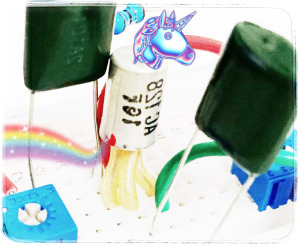
Nous allons revenir ici sur le boost qui utilise des transistors au germanium de récupération. L’un de vous m’a demandé une photo du circuit, je me suis dit qu’en plus de la photo un dessin du protoboard serait plus clair, et tant qu’à faire, autant le partager ici ! 😊
Pour le circuit utilisé vous pouvez consulter l’article cité ci-dessus.
Le transistor que j’utilise ici est un AC128, très…
View On WordPress
0 notes
Text

I made a thing for my boss (he's a great boss)
(i also did all the led wiring myself and it only took me three rounds of incorrect math and two revisions of the protoboard T_T)
24 notes
·
View notes
Text

Working on some more circuit bending! Now I've got a nice little protoboard with some convenient test points. Next step is to get the feedback circuit together.
(also gotta figure out how to mount the damn thing and all its fiddly bits)
7 notes
·
View notes
Text
I decided today that I should build my own version of ⅔ of the old Mutable Instruments module Kinks — the top two sections, leaving off the sample and hold. To review, the first section takes a single input and yields its inverse and both a half-wave and full-wave rectified version; the second takes two inputs and outputs their voltage maximum and minimum, aka their analog OR and AND. I'm throwing in an extra circuit to the second section that's said to be the analog equivalent of an XOR, supposed to act much like a ring mod.
I'm planning on building it on protoboard from parts I have on hand, and because I'm terribly impatient and a little obsessive, I've just spent a couple of hours whomping up a faceplate from some scrap sheet aluminum without any power tools.

The top mounting hole is for an LED following the polarity section's input, and the rest are for jacks. I've long tried to follow a convention of inverting the background of output jacks, just for that extra bit of clarity; I may still need to give that white another coat of paint marker before I start labeling.
Anyway, I'm trying to better document progress on these projects I'm doing, so I'll keep you all posted.
12 notes
·
View notes
Text
The Amputated Franken-Plus
Last year I revived an old Mac Plus that had been destructively robbed for parts over the years. I added sockets for the chips that had been removed, gave it a new power supply, added my SE-VGA card for video, and bodged a few broken traces. But there still remained the most heinously destructive part removal that had been committed against this poor board ...
Long before I had mastery of a soldering iron, and lacking the proper tools for desoldering components successfully, I had a project where I needed n 8-pin mini DIN connector. I had this non-functional Mac Plus board gathering dust so I decided to remove one of its connectors. With a knife. By cutting the board around the connector.

I was young ...
Obviously, there's no repairing that. The board has a permanent chunk removed from it.
However, I find myself wanting to be able to use those serial ports now that I have the rest of the board running. There are lots of fun things to use them for, like LocalTalk networking, printers, zTerm, etc.
So I set out to build a breakout board to add the connectors for these serial ports back to the board. I started by digging up datasheets for the RS-422 & RS-232 transceivers Apple used, as well as schematics for the Plus and similar era Macs so I could trace out how the connectors were originally wired. It turns out all of the signals for both ports are routed to some RC filters in a straight line at the back of the board. This made it fairly easy to solder a ribbon cable to the filter pins on the back side of the board.

I've come to like ribbon cables; they're easy to work with. I can just crimp an IDC connector on one end and attach them to some pin headers. The breakout board itself is just some generic protoboard, and has said pin headers and two female 8-pin mini-DIN connectors.

It's not ideal. The ribbon cable wires are fragile and cold easily be pulled off the motherboard. But hopefully this will restore the last lost functionally for this poor tortured Mac Plus motherboard.
I plan to include the Franken-Plus in my exhibit for VCF Southwest in Richardson, Texas this weekend (23-25 June 2023). If you're in the area, definitely stop by; it's shaping up to be a great show.
25 notes
·
View notes
Text
Business in the front, party in the back. Yes, I'm leaving the button like that. It's fine.
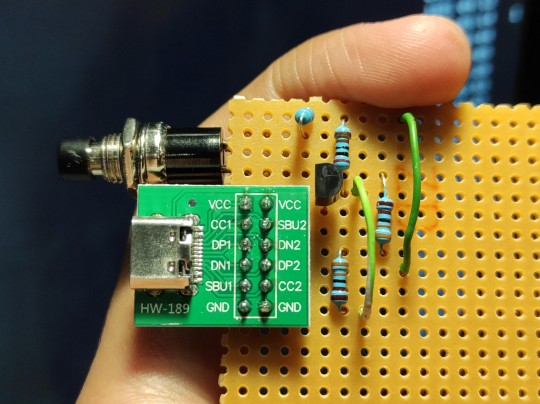

This is a Qualcomm Quickcharge Trigger, based loosely on this design, but only rigged for 12V.
When you press the button, it negotiates up from 5V to 12V from any QC 2.0 compatible charger.
Why? The 12V supply that runs my desk is a noisy, cheap pile of garbage that whines at 18kHz all the time, and my hearing is still good enough to hear that all goddamn night. Finding quiet 12V supplies that don't develop inscrutable hums a few months down the line is a crapshoot. On the other hand, cellphone chargers are usually impossibly quiet. I have a loose QC phone charger that I don't need for anything else, so if I can convince it to pump out 12V I can use that to run my desk. Hence, this pile of junk.
Tested and working, all I have to do is press the button to get it to put out 12V. Eventually I might get a 9V zener diode and an LED and set up an indicator that tells me if it's in 12V mode, but for now I'll lean on the fact that I built it and I know how it works.
This is NOT fully wired correctly, as in if you plug the USB cable in upside down it will not trigger correctly. Fixing this is not too hard but would require me to fuck around with the protoboard more than I already have and dealing with protoboard is miserable. I'll just put some alignment markers on the cable I'm using I guess.
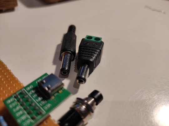
I'll have to sit later with a hacksaw and cut this section of protoboard out. Bleh. Building a case for things like this is what makes me wish I had a 3D printer. The exposed pins on the bottom are a short risk so this will get a chunk of cardboard two-way taped to the bottom.
If you ever get a chance to stock up on industry standard barrel jacks, do it, I use these things everywhere.
Quickcharge is a dying protocol, being replaced almost wholly by USB-PD, but USB-PD requires putting an actual microcontroller in the mix whereas this can be done fully analogue, and I believe that even QC 3.0 is still simple enough that a human with some buttons and a few resistor ladders could query basically any voltage it can supply (which is many)
71 notes
·
View notes
Text
Circuito con Infrarrojo
Materiales:
Led
Led Emisor y Led Receptor
Resistencia 1KΩ (2)
Resistencia 100KΩ (1)
Transistor N2222A
Protoboard
Desarrollo:
Primero iniciamos conectando una resistencia de 1KΩ al positivo del protoboard conjuntamente con conectar el positivo del Led Emisor (Transparente) a esta resistencia, a su vez del terminal negativo del Led Emisor conectamos un puente al negativo del protoboard.
Después conectamos un puente desde negativo del protoboard hasta el positivo del Led Receptor (Negro) ademas que desde el negativo de este Led conectamos la resistencia de 100KΩ a positivo del protoboard que a su vez conecta un puente a la base del transistor donde se conecta en su emisor el Led (azul) a positivo y en su colector la segunda resistencia de 1KΩ a positivo.

Cuando vemos que no se enciende una vez hecha la conexión lo único que falta es interrumpir la señal infrarroja que hará que se prenda el Led.

Video:
youtube
3 notes
·
View notes
Link
Módulo Fonte de Alimentação para Protoboard 5V 3,3V https://www.te1.com.br/?p=45001 Por Toni Rodrigues Toni Eletrônica Circuitos...
0 notes
Text
Anyone here knows about DIY stuff? Any intelligent way to join together PCB protoboards, cardboard and "wood" that isn't "glue, spit and praying for a while it stays together"?
0 notes
Text
Una posible propuesta de proyecto más grande o quizá final, sería esta (desarrollando la misma idea)
Componentes:
Placa Arduino : Utiliza una placa Arduino Uno o similar como el cerebro del proyecto. Esto te permitirá controlar las luces LED de forma programada.
LEDs : Necesitarás tres LEDs para representar las palpitaciones del corazón. Puedes elegir LED de diferentes colores para añadir un efecto visual interesante.
Potenciómetro : Utilice un potenciómetro para controlar la velocidad de parpadeo de los LED. Esto te permitirá ajustar la velocidad según tus preferencias.
Resistencias : Asegúrese de incluir una resistencia para cada LED para limitar la corriente y evitar daños a los componentes.
Cables de conexión : Necesitarás cables para conectar los componentes entre sí.
Protoboard : Utiliza una protoboard para realizar las conexiones de forma provisional antes de soldar los componentes en un circuito permanente.
Espejos : Para el montaje final, puede utilizar espejos o superficies reflectantes que puedan mostrar las palpitaciones de los LED de una manera interesante y estética.
Montaje:
Conecte los LED a la placa Arduino Uno utilizando las resistencias para limitar la corriente. Puedes conectar cada LED a un pin digital diferente de la placa.
Conecte el potenciómetro a la placa Arduino para controlar la velocidad de parpadeo de los LED. Puedes conectar el potenciómetro a un pin analógico de la placa.
Programe la placa Arduino utilizando el software Arduino IDE para que los LED parpadeen de forma independiente y la velocidad de parpadeo sea controlada por el potenciómetro.
Una vez que el circuito esté funcionando correctamente, puede montar los componentes en una caja o estructura adecuada y colocar los espejos o superficies reflectantes de manera que reflejen las palpitaciones de los LED de una manera interesante y visualmente atractiva.
Con estos componentes y pasos, podrás crear un proyecto de electrónica que simula las palpitaciones de un corazón, con la posibilidad de mostrarlas de forma visualmente impactante utilizando espejos o superficies reflectantes.
0 notes
Text
Woo, got some zero ohm resistors and nice perfboards in. Stripboard is great and very adaptable, but the convenience of perf boards already laid out with trace patterns is nice. Sometimes you don't want to spend a couple hours figuring out which strips you gotta cut and where, you want to pop parts in like a protoboard.
I got a few pieces of 2-3-5 pattern, which you can still cut the large traces for that flexibility but the point is minimal layout.
#nicoisms#only complaint I have is the busses on the 2-3-5 perf have no holes so I'll have to do that myself to use them
0 notes
Text
What Is A Protoboard?
A protoboard is a fundamental component in the field of electronics, serving as an essential tool for both beginners and professionals in circuit design. In this article, we will explore what a protoboard is, how to use it, and how it differs from a breadboard.
Introduction to Protoboards: Protoboards, also known as prototype boards, hold a crucial place in the realm of electronics. They are indispensable for creating permanent electronic circuits, moving beyond the temporary designs often assembled on breadboards.
Permanence: The primary advantage of protoboards is their ability to create permanent circuits. Unlike breadboards, which are excellent for temporary and experimental setups, protoboards enable the creation of stable and enduring connections by soldering components directly onto the board. This permanence is ideal for finalized projects.
Design and Usability: At first glance, a protoboard appears as a grid of holes designed to accommodate various electronic components. However, this grid is not merely a design feature; it is a carefully planned layout that facilitates organized and efficient circuit construction. Whether you are building a simple LED setup or a complex project based on a microcontroller, the layout of the protoboard offers the flexibility and order required for the task.
Versatility: Protoboards are highly versatile and suitable for a wide range of electronic projects. They are not limited to beginner-level endeavors but serve as a foundation for intricate and sophisticated designs. This versatility makes them a preferred choice among experienced electronics enthusiasts and professionals.
Suited for the Experienced: It is important to note that protoboards are particularly well-suited for individuals with some experience in electronics. Soldering demands precision and knowledge, making protoboards a step up from the more beginner-friendly breadboards.
Compatibility with Advanced Systems: For users of systems like PicoBricks, protoboards provide an excellent platform for constructing more advanced and permanent projects. They establish robust connections essential for complex designs, ensuring that your project is not just a fleeting experiment but a lasting creation.
Breadboard vs. Protoboard: Breadboards, with their non-permanent, solder-free design, are perfect for beginners and temporary projects, offering flexibility and cost-effectiveness. Protoboards, on the other hand, are ideal for more advanced, permanent installations, providing a sturdy and compact solution for complex circuits.
Flexibility: Breadboards are well-suited for temporary and experimental projects due to their reusable nature, allowing easy insertion and removal of components without soldering. Protoboards, conversely, are designed for permanent circuits as they require soldering, delivering a more stable and durable connection.
Complexity: Breadboards are more user-friendly, making them suitable for beginners or those new to PicoBricks due to their no-soldering approach. Protoboards are better suited for complex and finalized projects where a permanent circuit is necessary.
Size and Portability: Breadboards come in various sizes, making them suitable for projects of different scales. Protoboards are more compact and robust, making them suitable for portable or space-constrained projects.
Cost: Breadboards are generally more cost-effective for prototyping, while protoboards may involve additional expenses due to the need for soldering equipment and materials.
0 notes
Text
0 notes
Text
This isn't going to mean anything to anyone, but I finally got this goddamn circuit to work. (The working one is on the right , remnants of 2 others for posterity). It's like baby's first circuit and I did the electronics equivalent of copy-pasting code from StackOverflow. But the first 2 protoboards I tried were not good for people who fuck up a lot so I had to special order one. Finally against all odds I have managed to make some lights blink.
Normalize being bad at crafts, I guess!

1 note
·
View note
Text
Well, hell.
My oscilloscope module is built around an off-the-shelf board, the XProtoLab. It's a tiny device, released in 2011, that was designed to snap into a breadboard; it displays its two analog or eight digital inputs on its tiny OLED screen.


Which is apparently the part on mine that just quit working. Once I took it out of the module and hooked it up to a PC, it connected to the 'scope display program over USB just fine, but I can't seem to convince it to show anything on the screen itself.
This wouldn't be too terrible, as the advantage of a block solution like this is that you can easily drop in a replacement. Unfortunately, the manufacturer hasn't made these things since around 2018 or so. (It was also about $55 when it was available, which is cheap for an oscilloscope but expensive for my current pockets.) It looks like they might still sell a kit version ($35), but again, this is a tiny board — it's mostly covered by the 1" screen — and I'm not terribly confident in my surface mount soldering abilities. I might be able to just swap the screen out — I have an identically sized OLED screen on a protoboard around here someplace — but again, that's a difficult operation.
I may have to back-burner any repairs for now, and potentially just write off the effort and parts that got the module running a bit over a year ago. At least I do have some modules that aren't in my case currently that'd be a lot more useful than a broken oscilloscope.
7 notes
·
View notes
Text
830 Points Solderless Breadboard
An electronics prototyping platform is known as a breadboard or protoboard. It was originally just a bread board—a polished piece of wood for slicing bread. The solderless breadboard, also known as a plugboard or a terminal array board, was introduced in the 1970s, and today the word "breadboard" is frequently used to describe these. Prototype is another word for "breadboard."
0 notes