#tempsensor
Explore tagged Tumblr posts
Visit Tumblr Blog
Explore Tumblr blogs with no restrictions, modern design and the best experience.
Last Seen Tumblr Blogs


Fun Fact
69% of Tumblr users are millennials.
Text
Urinary Catheters Industry Outlook: Demand Trends and Market Opportunities
The global urinary catheters market is expected to reach USD 8.0 billion by 2030, registering a CAGR of 5.4% from 2023 to 2030, according to a new report by Grand View Research, Inc. Increasing number of patients suffering from urinary tract infections (UTI) and blockages in the urethra are anticipated to boost the product demand. The advent of technologically advanced products is also expected to drive market growth. For instance, RIOCATH - a Reversal Inside Out Catheterization, developed by Riocath global in collaboration with IOCB Prague, reduces the chances of infections in the body.
The COVID-19 pandemic had a positive impact on the urinary catheters market. The National Center for Biotechnology Information (NCBI) reported in 2020 that the use of indwelling urinary catheters, as well as Central Venous Catheters (CVC), increased during the early stages of the COVID-19 pandemic, which is expected to boost the market. Moreover, several manufacturers are offering products such as coated urine catheters with temperature monitoring to ICU patients as stronger protection against secondary infections, which is expected to boost the market growth in the coming years.
Furthermore, technological advancements play a crucial role in fueling market growth. For instance, miniaturized catheters & introduction of antimicrobial catheters to reduce catheter-associated infections are expected to favor the urinary catheter market growth. In April 2020, Bactiguard launched a new urinary catheter- BIP Foley TempSensor, for patients in intensive care, surgery, and other conditions where continuous temperature monitoring is important.
Urinary Catheters Market Report Highlights
In terms of product, the intermittent catheters segment dominated the overall market for the largest revenue share of over 57.5% in 2022. This can be attributed to the increasing number of patients suffering from various urinary disorders
Urinary Incontinence (UI) emerged as the largest application segment and accounted for the largest revenue share of more than 37.1% in 2022, owing to the increasing prevalence of the disease. Factors such as surgery of the prostate gland, spinal cord injury, injury to the bladder nerves, blockage in the urine due to kidney stones, and blood clots in the urine can cause UI
North America dominated the market with the highest revenue share of 34.4% in 2022, owing to a high incidence rate of chronic disorders as well as the availability of highly skilled physicians on this continent
Urinary Catheters Market Segmentation
Grand View Research has segmented the global urinary catheters market based on product, application, type, gender, end-user, and region:
Urinary Catheters Product Outlook (Revenue, USD Million, 2018 - 2030)
Intermittent Catheters
Foley/ Indwelling Catheters
External Catheters
Urinary Catheters Application Outlook (Revenue, USD Million, 2018 - 2030)
Benign Prostate Hyperplasia & Prostate Surgeries
Urinary Incontinence
Spinal Cord Injury
Others
Urinary Catheters Type Outlook (Revenue, USD Million, 2018 - 2030)
Coated Catheters
Uncoated Catheters
Urinary Catheters Gender Outlook (Revenue, USD Million, 2018 - 2030)
Male
Female
Urinary Catheters End-user Outlook (Revenue, USD Million, 2018 - 2030)
Hospital
Clinics
Long-Term Care Facilities
Others
Urinary Catheters Regional Outlook (Revenue, USD Million, 2018 - 2030)
North America
US
Canada
Europe
Germany
UK
France
Italy
Spain
Denmark
Sweden
Norway
Asia Pacific
Japan
China
India
Australia
South Korea
Thailand
Latin America
Mexico
Brazil
Argentina
Middle East and Africa
South Africa
Saudi Arabia
UAE
Kuwait
List of Key Players
Hollister, Inc.
Medtronic PLC
Boston Scientific Corp.
BD (C.R. Bard, Inc.)
Cook Medical
ConvaTec, Inc.
Teleflex, Inc.
Coloplast
Braun Melsungen AG
Medline Industries, Inc.
J and M Urinary Catheters LLC.
Order a free sample PDF of the Urinary Catheters Market Intelligence Study, published by Grand View Research.
0 notes
Text
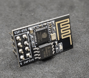
ESP-01S Temperatursensorshield DS18B20 Teil 2: Webseite mit Sensordaten erweitern

In diesem zweiten Teil möchte ich speziell darauf eingehen, wie du eine kleine Webseite für den ESP-01S mit dem Temperatursensor DS18B20 erstellen kannst. https://youtu.be/SeniGF1OMT8 Den ersten Teil zu diesem Beitrag findest du unter Arduino Lektion 81: ESP-01S Temperatursensorshield DS18B20 in diesem Beitrag hatte ich dir gezeigt, wie die Daten in einem JSON ausgeben werden können. Die Anzeige der Daten auf einer Webseite ist aber auch nicht viel schwerer, was du gleich erfahren wirst.

Was wird für dieses kleine Projekt benötigt?
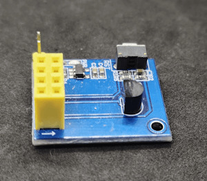
Du benötigst nachfolgende Module zum Programmieren und messen der Sensordaten: - einen ESP-01S*, - ein Modul mit Temperatursensor DS18B20*, - ein USB-Programmer* für den ESP-01S, - ein Jumper - Universal Netzteil* Zusätzlich benötigst du noch ein Netzteil, welches eine Spannung von 3,7V bis max. 12V liefert. Wobei ich meines auf 4V einstelle. Hinweis von mir: Die mit einem Sternchen (*) markierten Links sind Affiliate-Links. Wenn du über diese Links einkaufst, erhalte ich eine kleine Provision, die dazu beiträgt, diesen Blog zu unterstützen. Der Preis für dich bleibt dabei unverändert. Vielen Dank für deine Unterstützung!
Programmieren einer Webseite mit Sensordaten des DS18B20 am ESP-01S in der Arduino IDE
Aus dem ersten Beitrag entnehme ich das kleine Beispiel mit der Ausgabe als JSON und forme diese einfach als HTML Seite um.
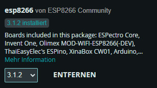
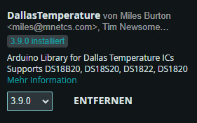
Programm - Anzeige der Sensordaten eines DS18B20 am ESP-01S auf einer WebseiteHerunterladen Schritt 1 - Import der benötigten Bibliotheken Für den Mikrocontroller ESP-01S benötigen wir zusätzlich einen Boardtreiber. Diesen können wir installieren wenn wir zuvor die nachfolgende Adresse den zusätzlichen Boardverwalter URLs hinzufügen. https://arduino.esp8266.com/stable/package_esp8266com_index.json Des Weiteren benötigen wir noch die Bibliothek DallasTemperature von Miles Burton.
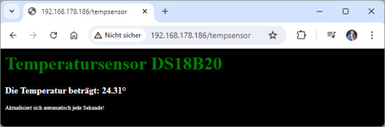
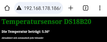
#include #include #include #include "secrets.h" Zusätzlich erzeuge ich die Datei secrects.h in welcher ich die Verbindungsdaten (SSID & Passwort) zum lokalen WLAN ablege. #define SSID "xxx" #define PASSWORD "yyy" Schritt 2 - aufbauen einer WiFi Verbindung zum lokalen WLAN Im zweiten Schritt bauen wir die WiFi Verbindung zum lokalen WLAN auf. Auch wenn der Mikrocontroller hinterher die Daten über die serielle Schnittstelle nicht mehr anzeigen kann, gebe ich im Code trotzdem die IP-Adresse aus. Jeder Router sollte den verbundenen Geräten immer dieselbe IP-Adresse vergeben, somit können wir zunächst im ersten Durchlauf ohne den Sensor die IP-Adresse auf dem seriellen Monitor ablesen können. const char* ssid = SSID; //SSID aus dem Router const char* password = PASSWORD; //Passwort für den Zugang zum WLAN ESP8266WebServer server(80); //Port auf welchem der Server laufen soll. void setup() { Serial.begin(9600); delay(10); //10ms. Warten damit die Seriele Kommunikation aufgebaut wurde. WiFi.begin(ssid, password); //Initialisieren der Wifi Verbindung. Serial.print("Aufbau der Verbindung zu "); Serial.println(SSID); while (WiFi.status() != WL_CONNECTED) { //Warten bis die Verbindung aufgebaut wurde. Serial.print("."); delay(500); } Serial.println(); IPAddress ip = WiFi.localIP(); Serial.print("IP-Adresse: "); Serial.println(ip); server.on("/tempsensor", callTempsensor); server.begin(); // Starten des Servers. } Schritt 3 - Erstellen einer kleinen Webseite für die Sensordaten Die kleine Webseite verfügt lediglich über eine Überschrift und zwei Paragrafen, in welche zum einen die Temperatur und zum anderen ein Hinweistext enthalten ist. void callTempsensor() { sensor.requestTemperatures(); String celsiusValue = String(sensor.getTempCByIndex(0)); String webseite = ""; webseite += ""; webseite += ""; webseite += "
Temperatursensor DS18B20
"; webseite += " Die Temperatur beträgt: {temp}°"; webseite += " Aktualisiert sich automatisch jede Sekunde!"; webseite += ""; server.send(200, "text/html", webseite); } Der CSS Stylesheet ist im Header -Bereich hinterlegt und lässt sich dort sehr einfach erweitern. webseite += ""; Zum Schluss wird der Platzhalter {temp} innerhalb des Strings mit dem Temperaturwert ersetzt. webseite.replace("{temp}", celsiusValue); fertiges Programm Nachfolgend das fertige Programm zum Anzeigen der Sensorwerte auf einer Webseite am ESP-01S.
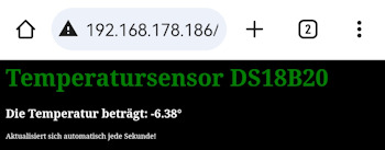
Zu einem Test habe ich das ganze mal in den Tiefkühlschrank gepackt und es werden hier auch die Minusgrade angezeigt. #include #include #include #include "secrets.h" #define ONE_WIRE_BUS 2 //Sensor DS18B20 am digitalen Pin 2 OneWire oneWire(ONE_WIRE_BUS); // //Übergabe der OnewWire Referenz zum kommunizieren mit dem Sensor. DallasTemperature sensor(&oneWire); const char* ssid = SSID; //SSID aus dem Router const char* password = PASSWORD; //Passwort für den Zugang zum WLAN ESP8266WebServer server(80); //Port auf welchem der Server laufen soll. void setup() { Serial.begin(9600); delay(10); //10ms. Warten damit die Seriele Kommunikation aufgebaut wurde. WiFi.begin(ssid, password); //Initialisieren der Wifi Verbindung. Serial.print("Aufbau der Verbindung zu "); Serial.println(SSID); while (WiFi.status() != WL_CONNECTED) { //Warten bis die Verbindung aufgebaut wurde. Serial.print("."); delay(500); } Serial.println(); IPAddress ip = WiFi.localIP(); Serial.print("IP-Adresse: "); Serial.println(ip); server.on("/tempsensor", callTempsensor); server.begin(); // Starten des Servers. sensor.begin(); //Starten der Kommunikation mit dem Sensor } void loop() { server.handleClient(); } void callTempsensor() { sensor.requestTemperatures(); String celsiusValue = String(sensor.getTempCByIndex(0)); String webseite = ""; webseite += ""; webseite += ""; webseite += "
Temperatursensor DS18B20
"; webseite += " Die Temperatur beträgt: {temp}°"; webseite += " Aktualisiert sich automatisch jede Sekunde!"; webseite += ""; webseite.replace("{temp}", celsiusValue); server.send(200, "text/html", webseite); } Read the full article
0 notes
Text
Light Density and Temperature Measurer

Overview
This project is about observing the temperature and density of light in the surroundings using sensors.
In this light density and temperature measurer we use a photoresistor sensor to measure light density and a temperature sensor for measuring temperature of the surrounding.
Hardware required
Arduino Uno R3
Resistor
Jumper Wires
Temperature Sensor
Photoresistor Sensor
Breadboard
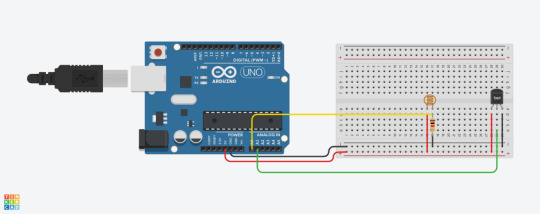
Fig 1. Circuit Diagram
Arduino Code : int lightSensor = A0; int tempSensor = A1; void setup() //Runs once at the start { pinMode(tempSensor, INPUT); pinMode(lightSensor, INPUT); Serial.begin(9600); } void loop() //Runs in a constant loop { //Just print a line for the light reading int lightReading = analogRead(lightSensor); Serial.print("Light reading: "); Serial.println(lightReading); int tempReading = analogRead(tempSensor); //If using 5v input float voltage = tempReading * 5.0; // Divided by 1024 voltage /= 1024.0; //Converting from 10mv per degree float tempC = (voltage - 0.5) * 100; Serial.print(tempC); Serial.println(" degrees C"); //Print as degrees delay(1000); //Use a delay to slow readings }
Precautions
Connections should be done properly.
Arduino is case Sensitive so code accordingly.
Give different and appropriate colors to the wires.
Use resistors for sensors and LCDs.
Do you have questions regarding our STEM program?
Contact us anytime.
Take your first step into the magical world of coding for kids
0 notes
Photo

Testing a small program that reads temperatures from a sensor with probe. Couldn't have picked a better day to demonstrate the span between the outside temperature a warm day and frozen ice lollipops in a freezer. And, well the ice cream is doing alright in the freezer 😎🥶🍨🍨way better than it would have outside. Just swipe to see the temp readings. Slide.1: Top: the temp sensor. Bottom: Arduino Uno board (Kjell edt.) with wires hooked up to the ground, 5V and data pins. Slide 2: Top: temp readings in vs out. Bottom: probe view (freezer/outside). #arduino #temperature #db18s20 #tempsensor #c++ #hotsummer #sommar #summer #heatwave #högtryck #høytrykk #embedded #glass #icecream #heat #coding #c #arduinouno #tech #microcontroller https://www.instagram.com/p/B0gtKZjomWX/?igshid=z0wn42oxzuj4
#arduino#temperature#db18s20#tempsensor#c#hotsummer#sommar#summer#heatwave#högtryck#høytrykk#embedded#glass#icecream#heat#coding#arduinouno#tech#microcontroller
1 note
·
View note
Photo

Any @trane #techs tell me if this is a standard #tempsensor or a retrofit sensor just doesn't look correct. Not saying it doesn't work just looks incredibly wrong and the cable tie is solid work but curious about this one.. #chillers #trane #chillertech (at Dublin, Ireland) https://www.instagram.com/p/Cf9f5N5L-qD/?igshid=NGJjMDIxMWI=
0 notes
Photo
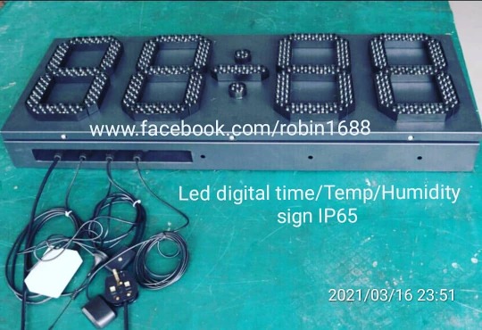
Multi Function #Leddigitalclock #timingiseverything #température #humility #timing #Clock #digitalclocks #Lightsensor #TempSensor #Humisensor #GPS #Autotiming(在 Shenzhen City Of China) https://www.instagram.com/p/CMfFPO3lwKk/?igshid=1iqvx3xsg5d5i
#leddigitalclock#timingiseverything#température#humility#timing#clock#digitalclocks#lightsensor#tempsensor#humisensor#gps#autotiming
0 notes
Text
ESP32 Arduino Tutorial 25-3. Protocol buffers: Encoding a DS18B20 temperature measurement
Introduction
In this tutorial we will check how to obtain a measurement from the DS18B20 temperature sensor and encode it using protocol buffers. We will be using the ESP32 and the Arduino core.
For an introduction on Nanopb, the protocol buffers library we are going to use, please check this previous tutorial. It explains how to install the library on the Arduino core and how to generate the message definitions from the .proto file.
For an introductory tutorial on the DS18B20 and how to connect it to the ESP32, please check here. The post also explains how to install the needed libraries.
So, for this tutorial, we will move one step forward and start using real measurements in our protobuf messages, since so far we have only been using dummy data. We will be fetching the measurements periodically and generating the corresponding protobuf messages.
The tests were performed using a DFRobot’s ESP32 module integrated in a ESP32 development board and a waterproof version of the sensor.
The .proto
Before we start coding, we need to define our message type, in a .proto file. We will be using the proto2 syntax.
We will call our message type “MeasurementMessage“. Its definition will be very simple since it will only contain a float field called “temperature“.
Since we only have one field, we will assign it the unique number 1. Additionally, our field will be required.
The final content of the .proto file can be seen below. As covered in the introductory tutorial, we need to compile our .proto file with the protoc compiler, in order to obtain the .h and .c files containing the message definitions and all the utilities needed to encode the message.
syntax = "proto2"; message MeasurementMessage { required float temperature = 1; }
I’ve called my file MeasurementMessage.proto, which means that the compilation procedure will generate the two following files:
MeasurementMessage.pb.h
MeasurementMessage.pb.c
As explained in the already mentioned tutorial, we should navigate to the Arduino sketch folder, create a new folder called “src“ and paste the generated files there, so we can import them in the Arduino code.
The code
As usual, we will start our code by the includes. The first one will be the include of the .h file created by the protoc compiler, which contains the C struct with our message definition. Recall that the .h and the .c files were placed in a folder called src, so we need to use that path in our include.
#include "src/MeasurementMessage.pb.h"
Followed by that, we should include the Nanopb library files.
#include "pb_common.h" #include "pb.h" #include "pb_encode.h"
To finalize the includes, we need the OneWire.h and the DallasTemperature.h, which are both used to interact with the DS18B20.
#include "OneWire.h" #include "DallasTemperature.h"
Next, we need an object of class OneWire, which is used under the hood by the DallasTemperature.h library to exchange data with the temperature sensor. As input, the constructor of this class receives the number of the microcontroller pin that is connected to the DS18B20. In my case, I’m using pin 22, but you can test with other pins.
Additionally, we will need to instantiate an object of class DallasTemperature, which is the one we are going to use to fetch our temperature measurements. The constructor of this class receives as input the address of our previously declared OneWire object.
OneWire oneWire(22); DallasTemperature tempSensor(&oneWire);
Moving to the setup function, we start by opening a serial connection, so we can output the messages generated by our program.
Additionally, we will call the begin method on our DallasTemperature object, in order for it to initialize the OneWire bus.
The whole setup function can be seen below.
void setup() { Serial.begin(115200); tempSensor.begin(); }
We will take care of obtaining the measurements and serializing them to the protobuf binary format on the Arduino main loop.
So, we will start by declaring a byte buffer to hold our serialized message. We will declare a buffer with 30 bytes, which is more than enough to accommodate our message.
After that, we will declare our message and initialize it. Recall from the previous tutorial that the name of the generated C struct is the same of the message type name defined in the .proto file, which means the struct is called MeasurementMessage.
We will also take advantage of the define that is generated during the compiling procedure, which allows to initialize the message. Recall that this define has the name of the message followed by “_init_zero“. You can confirm what this define does by looking into the MeasurementMessage.pb.h file.
uint8_t buffer[30]; MeasurementMessage message = MeasurementMessage_init_zero;
Next we will create the stream that is needed to write the serialized message to the memory buffer we just declared. We do this by calling the pb_ostream_from_buffer function, passing as first input the buffer and as second its size.
As output, the function will return a struct of type pb_ostream_t, which we will use later.
pb_ostream_t stream = pb_ostream_from_buffer(buffer, sizeof(buffer));
Before we serialize the message, we need to assign the temperature measurement obtained from the DS18B20 to the message temperature field.
To start a temperature conversion, we will first call the requestTemperaturesByIndex method of the DallasTemperature object, passing as input the index of the sensor we want to use. Since we have only one sensor attached to the OneWire bus, we use the index 0.
Finally, to obtain the actual temperature measurement, we call the getTempCByIndex method on the same object, passing as input also the index 0.
This method returns as output the temperature in degrees Celsius as a float, which means we can directly assign the value to the temperature field of our message struct.
tempSensor.requestTemperaturesByIndex(0); message.temperature = tempSensor.getTempCByIndex(0);
Now that we have the measurement assigned to our message temperature field, we can take care of the serialization procedure. So, to serialize the struct, we call the pb_encode function.
As first input, the function receives the address of our previously created stream. As second input, we need to pass the automatically generated fields description array, which has the name of the message appended by “_fields“. As third and final parameter, we pass the address of our message.
Note that this function call returns as output a Boolean value indicating if the procedure was successful (true) or not (false), which we will leverage for error checking.
bool status = pb_encode(&stream, MeasurementMessage_fields, &message); if (!status) { Serial.println("Failed to encode"); return; }
To finalize the code, we will print the temperature obtained from the sensor, so we can confirm it matches what is being encoded in the message. We can directly access the temperature value of our C struct.
Note that we will be printing the measurement with 2 decimal places, which is the default when we pass a float to the println method of the Serial object. If you want to use more decimal places, the println method can receive an additional value specifying how many decimal places should be used.
Serial.print("Temperature: "); Serial.println(message.temperature);
After that, we will print the encoded message in hexadecimal format.
Serial.print("Message: "); for(int i = 0; i<stream.bytes_written; i++){ Serial.printf("%02X",buffer[i]); }
The final code can be seen below. It already includes a 10 seconds delay between each iteration of the Arduino loop.
#include "src/MeasurementMessage.pb.h" #include "pb_common.h" #include "pb.h" #include "pb_encode.h" #include "OneWire.h" #include "DallasTemperature.h" OneWire oneWire(22); DallasTemperature tempSensor(&oneWire); void setup() { Serial.begin(115200); tempSensor.begin(); } void loop() { uint8_t buffer[30]; MeasurementMessage message = MeasurementMessage_init_zero; pb_ostream_t stream = pb_ostream_from_buffer(buffer, sizeof(buffer)); tempSensor.requestTemperaturesByIndex(0); message.temperature = tempSensor.getTempCByIndex(0); bool status = pb_encode(&stream, MeasurementMessage_fields, &message); if (!status) { Serial.println("Failed to encode"); return; } Serial.print("Temperature: "); Serial.println(message.temperature); Serial.print("Message: "); for(int i = 0; i<stream.bytes_written; i++){ Serial.printf("%02X",buffer[i]); } Serial.println(); delay(10000); }
Testing the code
To test the code, simply compile it and upload it to your ESP32 board, after finishing all the connections to the sensor. Once the procedure finishes, open the Arduino IDE serial monitor. You should get an output similar to figure 1, which shows the temperature measurements and the corresponding protobuf messages being periodically printed.
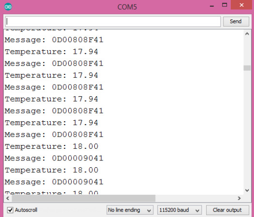
Figure 1 – Output of the program.
You can copy the messages and use this online tool to decode them and compare their value against the temperature measurements, as shown in figure 2. Nonetheless, recall that we have only used two decimal places when printing the temperature measurements directly but we did not change anything in the serialized value, so there may be a small difference in the values.

Figure 2 – Decoding one of the messages.
0 notes
Text
bee em eye

unbreak my mongo : then purge it :: hang the trousers : purge trousers : with fish :: get complete control over the edge : no more tempSensor : ever again :: exorcise the nurses : get serevent :: the ship lad food :: sports outlet : for unnecessary shit :: the white sofa shift :: bring turkey to the teuto-finn delegation : while peter plays live :: get down the sugar cane : refined :: have it all around bmi : and body fet :: teach maf to @migüel
0 notes
Text
Solar Winds and Kentix together!
Matt Soper/ Tanja Lewit June 5, 2018
This article will walk you through adding the Kentix Black Box Multi-Sensor Temperature and/or Humidity sensor to SolarWinds NPM. Additionally, you will be able to add other sensors to monitor if you have the OID of the sensor you wish to monitor.
We will assume you have downloaded the Kentix Control Center via Web Interface and have networking set up.
The Kentix dashboard, and are monitoring real time. Lets now send the information to Solar Winds-
we are know (easily) adding the physical aspects of monitoring our IT space.
Kentix Black Box Downloads and Manuals
Step 1: Enable SNMP
1. Launch the Kentix Control Center software and login. Navigate to Email, SNMP & GSM, you will see window on the right “SNMP Monitoring”.
2. Click in the box for “SNMP public community”, delete the default “public” string and enter new string name to something unique.
SNMP_1.pngSNMP_2.png
3. Click the icon to “Save” the new settings
Kentix_Save_settings.png
Step 2: Add Kentix Black Box in SolarWinds
1. Sign into SolarWinds, go to Settings, Manage Nodes, Add Node
2. Fill in the IP and SNMP community string that you just set from above steps
3. Click Next, then “OK, Add Node”
Your Kentix Black Box has now been added to SolarWinds and is monitoring ping. Next we will Create UnDP for the Temperature/Humidity Sensor.
Step 3: Adding Humidity and/or Temperature sensor in SolarWinds
1. Log into your SolarWinds NPM server and launch Orion Universal Device Poller
2. On the top menu bar click “New Universal Device Poller”
Kentix_1.png 3. Enter OID for the sensor you want to add, adjust settings to match below screenshot, then click Next
Temperature Sensor OID = 1.3.6.1.4.1.37954.1.2.2.2 Humidity Sensor OID = 1.3.6.1.4.1.37954.1.2.2.3 TempSensorAddOID.png
5. Select Node you want to assign the Custom Poller to, click test to confirm it is working, then click Next
Kentix_Assign.png
6. Leave the default setting “Use interface names from Orion”, then click Next
Kentix_Label.png
7. Change this selection to No and click Finish.
(The TempSensor is in Celsius so we will be defining a “Transform Results” to convert to fahrenheit and will display that in SolarWinds)
TempSensorWebDisplay.png
Step 4: Transform TempSensor Results from Celsius to Fahrenheit and Display in SolarWinds
1. Login into your SolarWinds NPM server and launch Orion Universal Device Poller
2. Select “Transform Results”
TransformResults.png
3. Click Next
TransformResults2.png
4. Enter Transform Results name “TempSensorFahrenheit”, match all the below settings, click Next
DefineTransformResults.png
5. Click Add Function and select “Celsius to Fahrenheit”
6. Click Add Poller and select “TempSensor”, make sure the Poller is inside the Functions Parentheses
7. Add /10 outside the } of the Poller to convert to decimal value, click Next
TempSensorFahrenheitTransformResults_Function.pngTempSensorFahrenheitTransformResults_Poller.png
8. Select Node you want to assign this Transform Results to, click test to confirm, then Next
TempSensorFahrenheitAssign.png
9. Leave Labels set to default option “Use interface names from Orion”, click Next
TempSensorFahrenheitLabels.png
10. Select Gauge and/or Chart, this will be displayed on the Node Details Summary page, then click Finish
TempSensorFahrenheitWebDisplay.png
TempSensorFahrenheitChart.pngTempSensorFahrenheitGauge.png
You are now monitoring your Kentix Black Box Temperature Sensor, if you want to add another sensor repeat Step 3. You will need to create Transform Results based on the sensor you add.
0 notes
Text
Urinary Catheters Market to Witness Huge Growth from 2023 to 2030
Urinary Catheters Industry Overview
The global urinary catheters market is expected to reach USD 8.0 billion by 2030, registering a CAGR of 5.4% from 2023 to 2030, according to a new report by Grand View Research, Inc. Increasing number of patients suffering from urinary tract infections (UTI) and blockages in the urethra are anticipated to boost the product demand. The advent of technologically advanced products is also expected to drive market growth. For instance, RIOCATH - a Reversal Inside Out Catheterization, developed by Riocath global in collaboration with IOCB Prague, reduces the chances of infections in the body.
The COVID-19 pandemic had a positive impact on the urinary catheters market. The National Center for Biotechnology Information (NCBI) reported in 2020 that the use of indwelling urinary catheters, as well as Central Venous Catheters (CVC), increased during the early stages of the COVID-19 pandemic, which is expected to boost the market. Moreover, several manufacturers are offering products such as coated urine catheters with temperature monitoring to ICU patients as stronger protection against secondary infections, which is expected to boost the market growth in the coming years.
Gather more insights about the market drivers, restrains and growth of the Urinary Catheters Market
Furthermore, technological advancements play a crucial role in fueling market growth. For instance, miniaturized catheters & introduction of antimicrobial catheters to reduce catheter-associated infections are expected to favor the urinary catheter market growth. In April 2020, Bactiguard launched a new urinary catheter- BIP Foley TempSensor, for patients in intensive care, surgery, and other conditions where continuous temperature monitoring is important.
Browse through Grand View Research's Medical Devices Industry Research Reports.
The global endoluminal suturing devices market size was valued at USD 73.6 million in 2024 and is projected to grow at a CAGR of 10.1% from 2025 to 2030.
The global ophthalmic drug delivery systems market size was estimated at USD 15.76 billion in 2024 and is projected to grow at a CAGR of 6.6% from 2025 to 2030.
Urinary Catheters Market Segmentation
Grand View Research has segmented the global urinary catheters market based on product, application, type, gender, end-user, and region:
Urinary Catheters Product Outlook (Revenue, USD Million, 2018 - 2030)
Intermittent Catheters
Foley/ Indwelling Catheters
External Catheters
Urinary Catheters Application Outlook (Revenue, USD Million, 2018 - 2030)
Benign Prostate Hyperplasia & Prostate Surgeries
Urinary Incontinence
Spinal Cord Injury
Others
Urinary Catheters Type Outlook (Revenue, USD Million, 2018 - 2030)
Coated Catheters
Uncoated Catheters
Urinary Catheters Gender Outlook (Revenue, USD Million, 2018 - 2030)
Male
Female
Urinary Catheters End-user Outlook (Revenue, USD Million, 2018 - 2030)
Hospital
Clinics
Long-Term Care Facilities
Others
Urinary Catheters Regional Outlook (Revenue, USD Million, 2018 - 2030)
North America
US
Canada
Europe
Germany
UK
France
Italy
Spain
Denmark
Sweden
Norway
Asia Pacific
Japan
China
India
Australia
South Korea
Thailand
Latin America
Mexico
Brazil
Argentina
Middle East and Africa
South Africa
Saudi Arabia
UAE
Kuwait
Key Companies profiled:
Hollister, Inc.
Medtronic PLC
Boston Scientific Corp.
BD (C.R. Bard, Inc.)
Cook Medical
ConvaTec, Inc.
Teleflex, Inc.
Coloplast
Braun Melsungen AG
Medline Industries, Inc.
J and M Urinary Catheters LLC.
Order a free sample PDF of the Urinary Catheters Market Intelligence Study, published by Grand View Research.
0 notes
Photo

SHANGHAI BAOLONG AUTOMOTIVE CORPORATION TEMP sensor-QY1026 (Z9F-TEMPSENSOR) http://dlvr.it/Q7MgmY
0 notes
Photo

I want to believe this is the right way to go for our earth, but what about the real world. #ihatebeingatestdummy #whengoinggreengoeswrong #takemebackwhenthingsweresimple keep your eye on the outdoor #tempsensor the thermostat wants to cycle on and off but the unit wants to run all days #turndownratio???? Lol
#tempsensor#whengoinggreengoeswrong#ihatebeingatestdummy#takemebackwhenthingsweresimple#turndownratio
1 note
·
View note
Photo

10inch White Color Led #digitalclock not only it #displays #actual #timetravel 12h or 24h by #GPS Auto Timing But also can display Temp with #TempSensor which can be changed together from #winghangsignsdotcom #facebookdotcomrobin1688(在 Shenzhen City Of China) https://www.instagram.com/p/CMfEoYaFaFc/?igshid=mv2tjx4kmght
0 notes
Text
ESP32 Arduino Tutorial: 25-2. Getting DS18B20 sensor unique identifier
Introduction
In this tutorial we will learn how to fetch the unique identifier of a DS18B20 sensor, using the ESP32 and the Arduino core. Please check this previous tutorial for the wiring diagram between the ESP32 and the sensor.
As covered in the mentioned previous tutorial, the DS18B20 uses the OneWire communication protocol. This protocol allows for more multiple devices to be connected to the same bus and each device has a unique factory programmed and non-changeable 64-bit address [1].
As also covered in the previous post, we can use the OneWire and the DallasTemperature libraries to interact with the sensor using a higher level interface, without the need to worry about the lower level details of the OneWire protocol.
One of the aspects we covered is that, when calling the methods to retrieve a temperature measurement, we can pass a device index, which corresponds to an integer representing from which device we want to get the measurement.
This is needed because, as already mentioned, multiple devices can be attached to the same bus and this works well if we don’t need to know from which specific sensor the measurement came from.
Nonetheless, for some applications, we may want to know from which specific device the measurements come from, so it is important to have a way of getting the device address. Furthermore, after knowing the address of the device, we can use it directly to fetch the measurements, rather than passing indexes, as can be seen by the header file of the DallasTempeature library.
So, in this tutorial, we will check how to get the unique address of a DS18B20 sensor by index, using the DallasTemperature library. Please note that the terms “address” and “identifier” are used with the same meaning during this post.
The tests were performed using a DFRobot’s ESP32 module integrated in a ESP32 development board and a waterproof version of the sensor.
The code
We will start our code by including the needed libraries. The first one is the OneWire.h, which allows to interact with devices using the OneWire protocol. The second one is the DallasTemperature.h, which will expose some higher level methods that will allow us to interact with the DS18B20 sensor.
#include "OneWire.h" #include "DallasTemperature.h"
After the includes, we will need an object of class OneWire, which allows to exchange bytes with devices connected to the OneWire bus. This object will be used internally by the DallasTemperature library to exchange the data with the sensor.
As input, the constructor of this class receives the number of the microcontroller pin connected to the sensor.
OneWire oneWire(22);
We will also need an object of class DallasTemperature, which is the one will use in our code to get the sensor address.
As input of the constructor of this class we will pass the address of our previously instantiated OneWire object.
DallasTemperature tempSensor(&oneWire);
Moving on to the setup function, we will start by opening a serial connection, to later output the address of the sensor.
Serial.begin(115200);
After that we will call the begin method on our DallasTemperature object. This method will be responsible for initializing the OneWire bus.
tempSensor.begin();
Next we need to declare a byte buffer to hold the ID of the sensor. Since, as already mentioned in the introductory section, the IDs have 64 bits, it means we will need an array with a length of 8 bytes.
uint8_t address[8];
To get the identifier, we simply need to call the getAddress method of the DallasTemperature object, passing as first input our byte buffer and as second input the index of the device we want to check. Since we only have one sensor attached to the OneWire bus, we use the index 0.
This method returns true if the device was found, so we will use the returning value to perform an error check.
if(tempSensor.getAddress(address, 0)){ Serial.print("Address fetched:"); }else{ Serial.println("Error fetching the address"); return; }
To finalize, we will print each byte of the address in hexadecimal format.
for(int i = 0; i<8; i++){ Serial.printf("%02X ",address[i]); }
The final source code can be seen below.
#include "OneWire.h" #include "DallasTemperature.h" OneWire oneWire(22); DallasTemperature tempSensor(&oneWire); void setup(void) { Serial.begin(115200); tempSensor.begin(); uint8_t address[8]; if(tempSensor.getAddress(address, 0)){ Serial.print("Address fetched:"); }else{ Serial.println("Error fetching the address"); return; } for(int i = 0; i<8; i++){ Serial.printf("%02X ",address[i]); } } void loop(void){}
Testing the code
To test the code, simply compile it and upload it to your ESP32, after performing all the electrical connections. Once the procedure finishes, open the Arduino IDE serial monitor. You should get an output similar to figure 1, which shows the 64-bit unique address getting printed.

Figure 1 – Output of the program.
0 notes
Text
Visualizing tempature
https://youtu.be/7-KDlvxAC_E
0 notes
Text
Arduino Lektion 81: ESP-01S Temperatursensorshield DS18B20

In diesem Tutorial möchte ich das Temperatursensor Shield DS18B20 für den ESP-01S vorstellen.
Bezug
Das Shield kann für ca. 1,8 € inkl. Versandkosten bei ebay.de bestellt werden.

ESP-01S DS18B20
Technische Daten
Betriebsspannung 3,7V bis max. 12V Temperatur Messbereich -55°C und +125°C Abmaße 25mm x 21mm
Aufbau des Shields

Aufbau des Temperaturshields
Schaltung
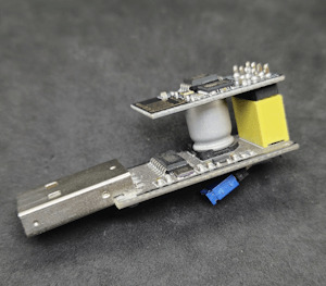
Die Schaltung ist relativ einfach denn der ESP-01s wird lediglich "nur" auf den Sockel gesteckt und das Shield mit Spannung versorgt. Beim Aufstecken sollte man auf den kleinen weißen Pfeil achten, dieser gibt die Richtung vor wie der ESP-01s aufgesteckt wird.

ESP-01S Temperaturshield DS18B20
Quellcode
Für den nachfolgenden Sketch benötigt man 2 zusätzliche Bibliotheken DallasTemperature OneWire Diese beiden Bibliotheken werden über den Bibliotheksverwalter installiert.

Bibliothek "DallasTemperature"

Bibliothek "OneWire" #include #include #include #define ONE_WIRE_BUS 2 //Sensor DS18B20 am digitalen Pin 2 OneWire oneWire(ONE_WIRE_BUS); // //Übergabe der OnewWire Referenz zum kommunizieren mit dem Sensor. DallasTemperature sensor(&oneWire); const char* ssid = ""; //SSID aus dem Router const char* password = ""; //Passwort für den Zugang zum WLAN ESP8266WebServer server(80); //Port auf welchem der Server laufen soll. void setup() { delay(10); //10ms. Warten damit die Seriele Kommunikation aufgebaut wurde. WiFi.begin(ssid, password); //Initialisieren der Wifi Verbindung. while (WiFi.status() != WL_CONNECTED) { //Warten bis die Verbindung aufgebaut wurde. delay(500); } server.on("/tempsensor", callTempsensor); server.begin(); // Starten des Servers. sensor.begin(); //Starten der Kommunikation mit dem Sensor } void loop() { server.handleClient(); } void callTempsensor(){ sensor.requestTemperatures(); String celsiusValue = String(sensor.getTempCByIndex(0)); String fahrenheitValue = String(sensor.getTempFByIndex(0)); String jsonRespond = "{\"celsius\": \""+String(celsiusValue)+"\" , \"fahrenheit\": \""+String(fahrenheitValue)+"\" }"; server.send(200, "application/json", jsonRespond); } Wenn man nun das Sketch auf dem ESP-01s kopiert hat und den Microcontroller auf das Shield gesteckt hat muss man nun noch die Betriebsspannung anlegen. Ich nutze dazu eine 9V Batterie welche über ein Power Modul auf 5V heruntergeregelt wird.

Aufbau, Schaltung ESP01s DS18B20 Shield Nachdem nun die Spannung anliegt versucht sich der ESP-01S in das WLAN Netzwerk anzumelden. Wenn man nun die IP-Adresse des ESP-01S in einem Browser eingibt dann öffnet sich folgende Seite:

ESP-01S , DS18B20 Shield, JSON Respond
Read the full article
0 notes