#using magnetic sensors to determine speed
Explore tagged Tumblr posts
Visit Tumblr Blog
Explore Tumblr blogs with no restrictions, modern design and the best experience.
Last Seen Tumblr Blogs


Fun Fact
Tumblr has been providing a Korean-language service since 2013.
Text
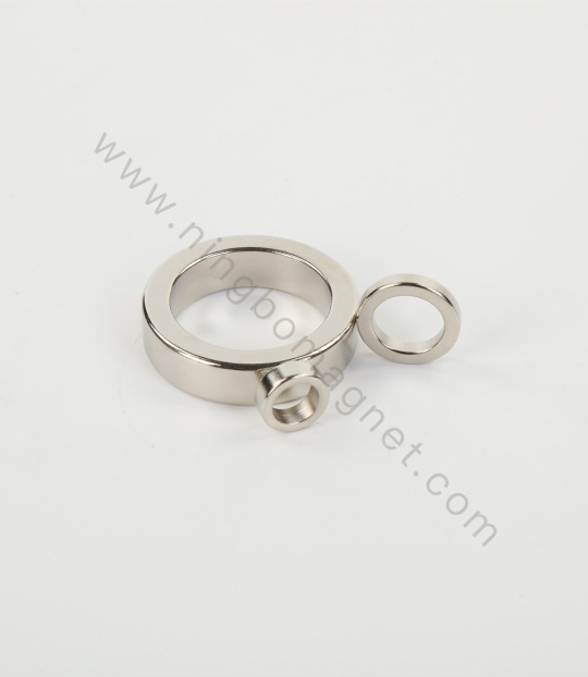
What You Need to Know About Arc Segmentitle Magnets, Radial Axial Circle Magnets, Isotropic and Anisotropic Magnets
Magnets serve an important part in a variety of sectors today, including electric motors, generators, sensors, and magnetic assembly. Among the several varieties available, the Arc Segmentitle Magnet, Radial Axial Circle Magnet, and the distinction between Isotropic and Anisotropic Magnets stand out for their performance, shape, and magnetic qualities. But what do these phrases signify, and where do these magnets usually appear?
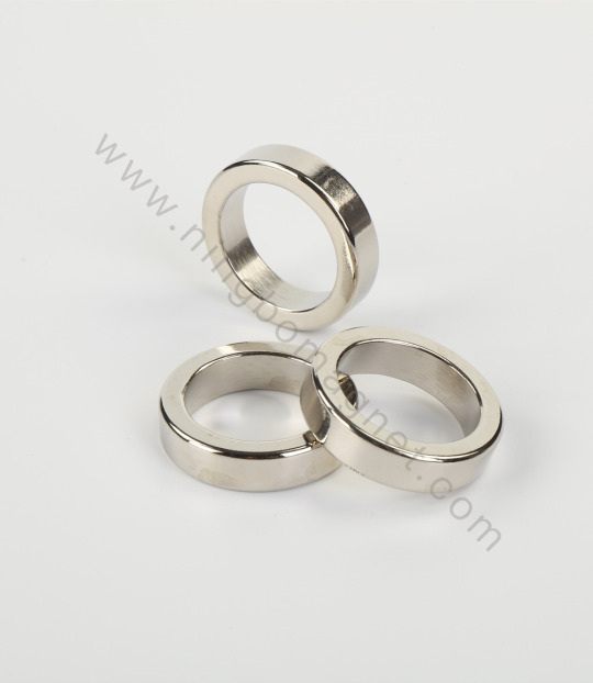
What is an Arc Segment Magnet?
An Arc Segment Magnet—an arc or segment magnet—is commonly employed in circular magnetic assemblies, notably brushless DC motors and permanent magnet motors. These magnets are shaped like a circle slice and are intended to be used around a rotor or stator.
Important characteristics:
Accurate curvature for a snug radial fit
Available in a variety of materials, such as ferrite, samarium cobalt, or neodymium (NdFeB).
Perfect for spinning systems with high speeds
High concentration of magnetic flux along the arc
Common Applications:
Drones and e-bikes with electric motors
Windmills
Couplings of magnets
Industrial robotics and servo motors
What Is a Radial Axial Circle Magnet?
A magnet with a circular or ring form with a magnetic direction that is either axial or radial is called a radial-axial circle magnet. The distribution of the magnetic field is determined by these orientations. In precision equipment, a radial-axial circle magnet is frequently specially made to meet certain torque or sensing requirements. Their specialized magnetic orientation and round shape guarantee little energy loss and excellent performance.
What Makes an Isotropic Magnet Different from an Anisotropic One?
Although materials like ferrite, neodymium, or rare earth compounds may be used to create both isotropic and anisotropic magnets, there are major differences in their production procedures and performance.
Conclusion
Knowing the differences between arc segmental magnets, radial axial circle magnets, and anisotropic / Isotropic Anisotropic Magnet magnets is essential for improving both your design and performance, whether you're an engineer creating the next high-efficiency motor or a manufacturer locating dependable magnetic components. Every magnet design and kind offers a unique set of benefits. Selecting the best one requires finding the ideal balance between cost-effectiveness, application fit, and magnetic strength.
Follow our Facebook and Twitter for more information about our product.
2 notes
·
View notes
Text
Crankshaft Sensor: Importance, Issues, and Maintenance Tips

The "Crankshaft Sensor" is a vital component in modern engines, ensuring proper timing and operation. It monitors the crankshaft’s position and rotational speed, sending data to the engine control unit (ECU). This information is crucial for managing fuel injection and ignition timing, ensuring optimal performance.
How the Crankshaft Sensor Works
Located near the crankshaft, this sensor detects the rotation using a magnetic or optical system. It generates signals that the ECU uses to determine the exact position of the crankshaft and the timing of each cylinder's stroke.
Common Crankshaft Sensor Issues
A faulty crankshaft sensor can lead to serious engine problems. Common symptoms include:
Difficulty starting the engine.
Engine stalling while driving.
Poor acceleration or misfires.
Check Engine light illumination.
A failing sensor disrupts the engine's timing, which can result in reduced efficiency and potential damage.
Maintenance Tips
1. Keep it Clean
Dirt and grime can affect the sensor’s readings. Periodically inspect and clean it.
2. Check Connections
Ensure the wiring and connectors are secure and free from corrosion.
3. Replace When Necessary
If symptoms appear, test the sensor and replace it promptly.
Maintaining your crankshaft sensor guarantees smooth engine operation and prevents costly repairs.
#crankshaft sensor#auto technician#auto mechanical#auto electrician#classic car#autos#cars#chevrolet#bmw#ferrari#audi
2 notes
·
View notes
Text

Simulation sheds light on Earth's magnetic field generation while advancing neuromorphic computing
How does the Earth generate its magnetic field? While the basic mechanisms seem to be understood, many details remain unresolved. A team of researchers from the Center for Advanced Systems Understanding at the Helmholtz-Zentrum Dresden-Rossendorf, Sandia National Laboratories (U.S.) and the French Alternative Energies and Atomic Energy Commission has introduced a simulation method that promises new insights into the Earth's core.
The method, presented in the Proceedings of the National Academy of Sciences, simulates not only the behavior of atoms, but also the magnetic properties of materials. The approach is significant for geophysics and could support the development of neuromorphic computing—an approach to more efficient AI systems.
The Earth's magnetic field is essential for sustaining life, as it shields the planet from cosmic radiation and solar wind. It is generated by the geodynamo effect. "We know that the Earth's core is primarily composed of iron," explains Attila Cangi, Head of the Machine Learning for Materials Design department at CASUS.
"As you get closer to the Earth's core, both temperature and pressure increase. The increase in temperature causes materials to melt, while the increase in pressure keeps them solid. Because of the specific temperature and pressure conditions inside the Earth, the outer core is in a molten state, while the inner core remains solid."
Electrically charged, liquid iron flows around the solid inner core driven by Earth's rotation and convection currents. These movements produce electric currents, which, in turn, generate the planet's magnetic field.
However, important questions about the Earth's core remain unanswered. For instance, what is the exact structure of its core? And what role do additional elements—thought to be present alongside iron—play? Both factors could profoundly influence the geodynamo effect.
Clues come from experiments where scientists send seismic waves through the Earth and measure their "echoes" with highly sensitive sensors. "These experiments suggest that the core contains more than just iron," says Svetoslav Nikolov from Sandia National Laboratories, lead author of the study. "The measurements do not agree with computer simulations that assume a pure iron core."
Simulating shock waves on the computer
The research team has now achieved significant progress by developing and testing a new simulation method. The key innovation of the method, called molecular-spin dynamics, lies in the integration of two previously separate simulation approaches: molecular dynamics, which models atomic motion, and spin dynamics, which accounts for magnetic properties.
"By combining these two methods, we were able to investigate the influence of magnetism under high-pressure and high-temperature conditions on length and time scales that were previously unattainable," emphasizes CEA physicist Julien Tranchida.
Specifically, the team simulated the behavior of 2 million iron atoms and their spins to analyze the dynamic interplay between mechanical and magnetic properties. The researchers also employed artificial intelligence (AI), using machine learning to determine force fields—interactions between atoms—with high precision. Developing and training these models required high-performance computing resources.
Once the models were ready, the researchers performed the actual simulations: The digital model of 2 million iron atoms, representative of the Earth's core, was subjected to the temperature and pressure conditions found in the Earth's interior. This was done by propagating pressure waves through the iron atoms, simulating their heating and compression.
When the speed of these shock waves was lower, the iron remained solid and adopted different crystal structures. When the shock waves were faster, the iron became mostly liquid. In particular, the researchers found that magnetic effects significantly affect the material's properties.
"Our simulations agree well with the experimental data," says Mitchell Wood, a materials scientist at Sandia National Laboratories, "and they suggest that under certain temperature and pressure conditions, a particular phase of iron could stabilize and potentially affect the geodynamo."
This phase, known as the BCC phase, has not been experimentally observed in iron under these conditions, only hypothesized. If confirmed, the results of the molecular-spin dynamics method could help resolve several questions about the geodynamo effect.
Driving energy-efficient AI
Beyond uncovering new details about the Earth's interior, the method also has the potential to drive technological innovations in materials science. Both in his department and through external collaboration, Cangi plans to use the technique to model neuromorphic computing devices.
This is a new type of hardware inspired by the way the human brain works, which could one day process AI algorithms faster and more energy-efficiently. By digitally replicating spin-based neuromorphic systems, the new simulation method could support the development of innovative, efficient hardware solutions for machine learning.
Data storage offers a second compelling avenue for further research: Magnetic domains along tiny nanowires could serve as storage media that are faster and more energy-efficient than conventional technologies.
"There are currently no accurate simulation methods for either application," says Cangi. "But I am confident that our new approach can model the required physical processes in such a realistic way, that we can significantly accelerate the technological development of these IT innovations."
2 notes
·
View notes
Text
Speed sensing is very important in industrial applications in which process control require precise speed control of production belts to control the rate of manufacturing and also in robotics and autonomous system to determine the exact position of the arm or the tool and its movement. In industry we use two types of speed sensors magnetic induction sensors and Infrared sensors. This 4 Pin Infrared Speed Sensor Module is used in the speed control applications where you need to read rotation of a disk. It is powered by any of the 3.3V or 5V supply and gives digital output, which you can easily read with the help of interrupt function on your microcontroller or development board.
3 notes
·
View notes
Text
How Magnetic GPS Trackers Work and Why They’re Ideal for Tracking
As asset and vehicle tracking becomes an essential component of modern business operations and personal safety, magnetic GPS trackers are gaining popularity for their discreet design, ease of use, and powerful functionality. These compact devices offer a smart, no-fuss solution for monitoring cars, bikes, containers, or any valuable movable property without the need for hardwiring or permanent installation.
Whether you’re managing a fleet, monitoring logistics, or enhancing personal vehicle security, understanding how magnetic GPS trackers work can help you decide if they’re the right fit for your tracking needs.
What Is a Magnetic GPS Tracker?
A magnetic GPS tracker is a small, portable GPS device equipped with high-strength magnets that allow it to be easily attached to a vehicle or metal surface. Unlike traditional wired trackers, it requires no installation expertise, which makes it ideal for temporary or hidden tracking scenarios.
These devices use Global Positioning System (GPS) technology to determine their precise location and send that data via mobile networks (GSM/4G) to a cloud platform or mobile app where users can view real-time updates.
How Magnetic GPS Trackers Work
The operation of a magnetic GPS tracker involves three core components:
1. GPS Module
The device receives satellite signals to calculate its exact position using triangulation. GPS signals help the device determine latitude, longitude, speed, and direction.
2. Cellular Transmitter (GSM/4G)
Once the location is calculated, the device sends this data to a central server via cellular networks. The more advanced models support real-time tracking and instant alerts using mobile or web platforms.
3. Power Supply
Magnetic GPS trackers typically run on rechargeable lithium-ion batteries. Battery life can range from a few days to several weeks or even months, depending on usage and reporting frequency.
Many trackers are equipped with motion sensors, which help extend battery life by activating only when movement is detected. Some models also offer a standby mode when idle.
Key Features of Magnetic GPS Trackers
Magnetic GPS trackers are designed to be versatile and low-maintenance. Here are the standout features that make them a preferred choice for many users:
Magnetic Mounting: No wiring required. Attach it under a vehicle or to any metal surface.
Real-Time Tracking: View live location updates via a mobile app or desktop dashboard.
Geo-Fencing: Set up virtual boundaries and receive instant alerts when the tracker enters or exits a designated area.
Movement Alerts: Get notified when the tracker starts moving or is tampered with.
Route History Playback: Review past travel routes for audit, billing, or verification purposes.
Water and Dust Resistance: Most trackers come with IP65 or higher ratings for outdoor use.
Long Battery Life: Varies from 10 days to several months, depending on model and usage.
Use Cases: Where Magnetic GPS Trackers Shine
1. Vehicle Surveillance and Anti-Theft
Attach a magnetic GPS tracker under a car or bike to monitor unauthorized movement and prevent theft. These trackers are often used by vehicle owners for peace of mind and by recovery services to track stolen assets.
2. Fleet Management
Businesses can deploy magnetic trackers to temporarily monitor new or rented fleet vehicles without modifying internal wiring or investing in permanent installations.
3. Asset Tracking
Track valuable cargo, shipping containers, or heavy equipment during transit or while in storage. The magnetic attachment allows for flexible placement based on the asset’s size and material.
4. Personal Use
Parents may use them to track teenage drivers, or individuals may use them to secure luggage during travel. They are also commonly used by investigative services or for law enforcement purposes (with appropriate legal permissions).
Advantages of Magnetic GPS Trackers
Quick Deployment: No tools or installation required.
Discreet Tracking: Compact size and magnetic design make it easy to hide.
Flexible Use: Easily move the device between vehicles or assets.
Cost-Effective: No installation cost, and many options are available for different budgets.
Remote Monitoring: Access location and data from anywhere via mobile apps.
Are There Any Limitations?
While magnetic GPS trackers offer great convenience, there are some limitations:
Battery Dependency: Unlike wired trackers, they rely on battery life. It's important to monitor and recharge as needed.
Signal Disruption: Tracking accuracy may drop in areas with poor GPS signal, such as underground parking lots or dense urban environments.
Tampering Risk: If not hidden well, the device could be discovered and removed.
Conclusion
Magnetic GPS trackers provide an ideal solution for individuals and businesses seeking a simple, effective way to monitor vehicles and movable assets. With no complex installation, powerful features, and flexible applications across industries, these trackers deliver both convenience and reliability.
From theft prevention to logistics optimization, the benefits of adopting magnetic GPS tracking are hard to ignore. As tracking technology continues to evolve, these devices offer a practical entry point into modern GPS-based asset monitoring.
If you’re considering a versatile tracking solution, a magnetic GPS tracker might just be the tool you need.
0 notes
Text
7 Warning Signs of a Failing Crankshaft Position Sensor You Shouldn't Ignore
https://autorepairlebanontn.com/?p=4072 7 Warning Signs of a Failing Crankshaft Position Sensor You Shouldn't Ignore Is your vehicle struggling to start, stalling unexpectedly, or showing warning lights on the dashboard? These frustrating issues might point to a failing crankshaft position sensor—a small but crucial component that monitors your engine’s rotational speed and position. When this sensor malfunctions, it can wreak havoc on your car’s performance and leave you stranded at the worst possible moments. We’ve helped countless drivers identify and address crankshaft position sensor problems before they escalate into costly repairs. In this guide, we’ll walk you through the seven telltale symptoms that indicate your crankshaft position sensor is on its last legs. Understanding these warning signs can save you time, money, and the headache of unexpected breakdowns. Table of Contents Toggle Understanding the Role of a Crankshaft Position SensorEngine Starting Problems: The First Warning SignCheck Engine Light IlluminationUnexpected Engine StallingPoor Acceleration and Performance IssuesErratic Idling BehaviorIncreased Fuel ConsumptionEngine Misfires and Rough RunningHow to Diagnose a Faulty Crankshaft Position SensorDIY Testing MethodsWhen to Seek Professional HelpReplacement Costs and ConsiderationsConclusionFrequently Asked QuestionsWhat is a crankshaft position sensor?What are the main symptoms of a failing crankshaft position sensor?Why is my car having trouble starting?Can a bad crankshaft sensor cause stalling?Will the check engine light come on with a bad crankshaft sensor?How does a failing sensor affect fuel economy?How much does it cost to replace a crankshaft position sensor?How is a faulty crankshaft position sensor diagnosed? Understanding the Role of a Crankshaft Position Sensor The crankshaft position sensor serves as a critical component in modern vehicle engines, monitoring the position and rotational speed of the crankshaft. Located near the main pulley or flywheel, this electronic device generates signals that the engine control unit (ECU) uses to determine ignition timing and fuel injection sequences. These precise measurements ensure your engine fires at exactly the right moment for optimal performance. Your vehicle’s ECU relies on this sensor’s data to make split-second adjustments to engine timing. Without accurate information from the crankshaft position sensor, the ECU can’t properly synchronize fuel injection and spark plug firing—leading to many drivability issues. The sensor typically consists of a magnetic pickup or Hall effect sensor that creates electrical pulses as the crankshaft rotates. Most modern vehicles employ this sensor as part of a sophisticated engine management system. As the toothed wheel on the crankshaft rotates past the sensor, it creates a changing magnetic field that generates voltage signals. These signals create a exact pattern the ECU interprets to determine the exact position of the pistons and crankshaft rotation speed. Engine performance depends heavily on the precise timing this sensor provides. Proper air-fuel mixture delivery and spark timing rely on accurate crankshaft position data. When functioning correctly, the sensor helps maintain smooth idling, consistent acceleration, and optimal fuel efficiency while reducing harmful emissions. Engine Starting Problems: The First Warning Sign Prolonged cranking or complete failure to start represents the most common symptom of a faulty crankshaft position sensor. Engines typically require extra time to turn over when this sensor malfunctions, as the powertrain control module (PCM) struggles to receive accurate positional data. Many drivers notice this problem manifests as turning the key and hearing the engine crank repeatedly without starting. Kickbacks or backfiring often accompany starting issues, particularly during initial startup attempts. These alarming sounds occur because the sensor isn’t properly synchronizing the ignition timing with the crankshaft’s position. Your vehicle might produce distinctive popping and banging noises during attempted starts—clear indicators of crankshaft position sensor failure. The starting problem typically progresses from intermittent to consistent over time. Initially, you’ll experience occasional difficult starts that become more frequent as the sensor deteriorates further. Cold mornings often exacerbate these symptoms, making the problem more noticeable when temperatures drop. Engine starting issues serve as an early warning sign that shouldn’t be ignored, as they frequently precede complete system failure. Check Engine Light Illumination The Check Engine Light serves as your vehicle’s primary warning system when the crankshaft position sensor begins to fail. This dashboard indicator illuminates when the sensor transmits incorrect signals or no signals at all to your vehicle’s computer system. Many drivers notice this warning light as the first indication of a potential crankshaft position sensor issue. The engine control module constantly monitors sensor performance and triggers this warning light when it detects inconsistencies in the data stream. Modern vehicles rely on precise timing information from the crankshaft position sensor to maintain optimal engine operation. When this communication breaks down, your car’s onboard diagnostics system immediately flags the problem. Diagnostic trouble codes related to crankshaft sensor failures often include P0335 (Crankshaft Position Sensor Circuit Malfunction) and P0336 (Crankshaft Position Sensor Range/Performance). These exact codes help technicians pinpoint the exact nature of the sensor malfunction. It’s important to note that while a glowing Check Engine Light doesn’t necessarily mean your crankshaft position sensor has failed, it definitely warrants prompt investigation. The warning light might appear intermittently at first before becoming a permanent fixture on your dashboard as the sensor deteriorates further. Professional diagnostic equipment can quickly determine if the crankshaft position sensor is indeed the culprit behind the illuminated warning light. Unexpected Engine Stalling Intermittent stalling represents one of the most common and dangerous symptoms of a failing crankshaft position sensor. Your vehicle might shut off completely without warning while you’re driving, creating potentially hazardous situations on busy roads or highways. This sudden stalling occurs because the erratic signals from a malfunctioning sensor confuse the engine control unit, disrupting the precise timing needed for combustion. Many drivers report their vehicles stalling at low speeds initially, such as when approaching a stop sign or idling at a traffic light. The engine’s computer relies on accurate crankshaft position data to maintain proper fuel injection and spark timing sequences. When this data becomes inconsistent or disappears entirely, the engine can’t maintain operation and simply shuts down. The unpredictable nature of this symptom makes it particularly troublesome. Your vehicle might run perfectly fine for days, then suddenly stall multiple times in a single trip. Temperature changes often exacerbate the problem, with many sensors showing increased failure rates during extreme hot or cold conditions. Restarting after an unexpected stall typically gets progressively more difficult as the sensor deteriorates further. You’ll notice this pattern evolving—what begins as occasional stalling eventually becomes more frequent until the vehicle becomes completely unreliable. This escalating pattern serves as a critical warning sign that shouldn’t be ignored. Safety concerns amplify the importance of addressing this symptom quickly. Losing power steering and brake assist during unexpected stalling creates dangerous driving conditions, especially at higher speeds or in heavy traffic. Diagnostic testing can confirm if the crankshaft position sensor is indeed the culprit behind these intermittent stalling episodes. Poor Acceleration and Performance Issues A failing crankshaft position sensor often manifests as noticeable power loss during acceleration. When this sensor malfunctions, the engine computer receives inaccurate timing signals for fuel injection and spark timing, resulting in sluggish throttle response and reduced engine performance. Cars with this issue struggle to maintain consistent power output, particularly when attempting to accelerate from a stop or while overtaking on highways. Engine misfires frequently accompany poor acceleration, creating a jerky driving experience that’s impossible to ignore. These misfires occur because the erratic signals from a defective crankshaft position sensor lead to miscalculated fuel injector pulse and spark timing. Drivers typically notice hesitation when pressing the gas pedal, followed by a sudden surge of power as the engine computer attempts to compensate for the incorrect timing data. Fuel economy suffers significantly with a bad crankshaft position sensor. The engine’s decreased efficiency from constant misfires and rough running conditions leads to increased fuel consumption. Also, advanced fuel-saving technologies like variable valve timing and cylinder deactivation may fail to function properly without accurate crankshaft position data, further reducing your vehicle’s gas mileage. Intermittent performance problems create frustrating driving experiences when dealing with a failing sensor. The engine might stumble or shake unexpectedly, especially under load conditions such as climbing hills or accelerating with passengers. These performance inconsistencies stem directly from the sensor’s inability to provide reliable data to the engine control module, causing the computer to make inappropriate adjustments to critical engine parameters. Engine roughness at idle represents another telltale sign of crankshaft position sensor failure. Your vehicle might vibrate excessively or run unevenly when stopped at traffic lights or in park. The rough idle occurs because the engine computer can’t properly synchronize fuel delivery and spark timing without accurate crankshaft position information, leading to combustion inefficiencies even at low RPMs. Erratic Idling Behavior Erratic idling behavior manifests when your engine runs at inconsistent speeds while the vehicle is stationary. Irregular RPM fluctuations during idle often indicate a failing crankshaft position sensor sending incorrect data to the engine control unit. The engine computer struggles to maintain proper timing for fuel injection and ignition when receiving faulty crankshaft position information. Many drivers notice their tachometer needle bouncing unpredictably between different RPM readings while idling at stoplights. Unstable idling typically occurs because the sensor can’t accurately track the crankshaft’s position and rotational speed. Your engine might suddenly dip below normal idle speed or unexpectedly surge higher without any throttle input. These idle fluctuations frequently accompany other drivability issues like hesitation, stalling, or rough running conditions. Cold mornings or hot weather conditions tend to exacerbate these erratic idle symptoms when the sensor is deteriorating. The connection between crankshaft sensor failure and idle problems stems from the engine’s timing requirements. Without precise crankshaft position data, the ECU cannot synchronize fuel delivery and spark timing effectively during low-speed operation. Diagnostic scans often reveal intermittent signal errors or voltage fluctuations from the crankshaft sensor circuit during problematic idle periods. Some vehicles display more subtle symptoms like slight vibrations or minor RPM variations that gradually worsen as the sensor continues to degrade. Increased Fuel Consumption A faulty crankshaft position sensor directly impacts your vehicle’s fuel efficiency, creating a noticeable decrease in miles per gallon. This critical component helps the Engine Control Unit (ECU) optimize the timing of fuel injection and spark ignition for maximum efficiency. When the sensor malfunctions, the ECU lacks accurate data about crankshaft position and rotation speed, leading to suboptimal combustion timing. Fuel economy typically drops by 3-4 MPG when driving with a bad crankshaft position sensor, as confirmed by diagnostic testing. The ECU compensates for missing or inaccurate timing signals by defaulting to a “safe mode” where it doses excess fuel to prevent engine damage. This conservative fuel management strategy prioritizes keeping the engine running over maintaining efficiency. Many drivers notice they’re filling up their tanks more frequently before identifying the underlying sensor issue. The problem often becomes apparent during highway driving when fuel consumption should be at its most efficient. Instead, the engine runs rich continuously, wasting fuel and creating additional strain on engine components. Tracking your vehicle’s fuel consumption provides an early indicator of potential crankshaft position sensor failure. The decline in efficiency happens gradually in most cases, making it easy to miss until the problem becomes severe. Regular monitoring of your vehicle’s MPG helps identify this symptom before more serious drivability issues develop. Engine Misfires and Rough Running Engine misfires and rough running are telltale indicators of a failing crankshaft position sensor (CKP). When this sensor transmits erratic signals to the Powertrain Control Module (PCM), the computer miscalculates critical timing for fuel injection and spark delivery. The inconsistent signals cause the engine to misfire, creating a noticeable shaking or stumbling sensation, particularly when the vehicle is under load. Drivers experience these symptoms as: Subtle vibrations through the steering wheel or seat during acceleration Stumbling or hesitation when pressing the gas pedal Jerky performance especially when climbing hills or overtaking Reduced power during normal driving conditions The rough running occurs because the PCM relies on precise crankshaft position data to synchronize the ignition and fuel systems. Without accurate timing information, the engine’s cylinders fire at incorrect intervals, disrupting the combustion sequence. This desynchronization not only affects performance but also contributes to increased emissions and potential damage to catalytic converters. Fuel and spark delivery problems resulting from a bad CKP sensor often worsen progressively. Initially, drivers might notice occasional hiccups or brief power losses, but as the sensor deteriorates further, the misfires become more frequent and severe. Engine roughness typically intensifies during exact operating conditions such as cold starts or when the engine reaches normal operating temperature. Many vehicles with faulty crankshaft position sensors display inconsistent symptoms—running smoothly one moment, then suddenly misfiring the next. This unpredictability stems from the sensor’s intermittent failure patterns, making diagnosis challenging without proper testing equipment. How to Diagnose a Faulty Crankshaft Position Sensor Diagnosing a crankshaft position sensor problem requires a systematic approach to identify the root cause. Our diagnosis process begins with a visual inspection of the sensor and its wiring for visible damage or corrosion. Next, specialized diagnostic equipment like an OBD2 scanner helps retrieve any trouble codes stored in the vehicle’s computer, while more advanced tools can test the sensor’s output signal against manufacturer specifications. DIY Testing Methods DIY crankshaft position sensor testing starts with locating the sensor near the crankshaft—typically found at the front of the engine by the crankshaft pulley, on the engine block, or near the transmission bell housing. After disconnecting the electrical connector, use a multimeter set to the resistance setting to test the sensor terminals. Normal resistance readings generally fall between 200 to 1,200 ohms, but always compare your results with specifications in your vehicle’s service manual. Carefully inspect all wiring connected to the sensor for signs of fraying, melting, or corrosion that could interrupt the signal. Testing the sensor with an oscilloscope provides more detailed analysis of the sensor’s performance during engine operation, allowing you to visualize the actual signal patterns being produced. When to Seek Professional Help Professional assistance becomes necessary when dealing with intermittent sensor symptoms that are difficult to reproduce during home testing. Technicians possess specialized diagnostic equipment that can monitor sensor performance under various operating conditions. Complex sensor installation procedures on certain vehicle models may require professional expertise, especially when the sensor location is difficult to access or requires special tools. Mechanics can also perform comprehensive testing to ensure the problem isn’t caused by related components like the wiring harness or engine control module. If your initial diagnosis attempts reveal inconsistent results or if replacing the sensor doesn’t resolve the issue, professional diagnostic services can save time and prevent unnecessary parts replacement. Replacement Costs and Considerations Replacing a crankshaft position sensor involves both parts and labor costs that vary depending on your vehicle’s make and model. The sensor itself typically costs between $40 and $150, with higher-end or luxury vehicles commanding premium prices for OEM parts. Labor charges can range significantly from $100 to $700, reflecting the accessibility of the sensor’s location and the complexity of the replacement procedure. Most vehicle owners can expect to pay a total of $100 to $400 for a complete crankshaft position sensor replacement. Luxury vehicles and complex engine designs often push this cost higher, potentially reaching $700 or more for the entire service. BMW models, for example, generally fall in the $200 to $400 range, while Hyundai and Kia vehicles typically cost between $100 and $300 for the same repair. Several factors influence the final cost of your crankshaft position sensor replacement: Vehicle Accessibility: Sensors that are difficult to reach require more labor time Dealer vs. Independent Shop: Dealerships typically charge more than independent mechanics OEM vs. Aftermarket Parts: Original equipment manufacturer sensors cost more but may provide better reliability Geographic Location: Labor rates vary significantly based on your region Vehicle Make and Model: European luxury vehicles generally incur higher replacement costs than domestic or Asian models DIY replacement can save substantial labor costs for those with mechanical experience. The procedure requires basic tools and mechanical knowledge, with the most challenging aspect often being accessing the sensor’s location. Many crankshaft position sensors are situated near the engine’s flywheel or behind the crankshaft pulley, making replacement more complicated in some vehicles than others. Conclusion Recognizing the seven symptoms of a failing crankshaft position sensor is crucial for maintaining your vehicle’s performance and safety. By staying alert to warning signs like starting difficulties check engine lights unexpected stalling poor acceleration erratic idling increased fuel consumption and engine misfires you’ll be better equipped to address issues before they escalate. Don’t ignore these symptoms as they often worsen over time leading to complete engine failure and potentially dangerous driving situations. Whether you choose DIY diagnostics or professional help prompt attention to these warning signs can save you from costly repairs and roadside emergencies. Remember that timely replacement of a faulty sensor is significantly more affordable than repairing the extensive damage that can result from continued operation with a failing component. Frequently Asked Questions What is a crankshaft position sensor? A crankshaft position sensor is an electronic device that monitors the position and rotational speed of your vehicle’s crankshaft. Located near the main pulley or flywheel, it sends crucial signals to the engine control unit (ECU) that determine ignition timing and fuel injection sequences. This component is essential for optimal engine performance, smooth idling, and fuel efficiency. What are the main symptoms of a failing crankshaft position sensor? The main symptoms include difficulty starting your vehicle, unexpected engine stalling, illuminated check engine light, poor acceleration and performance, erratic idling behavior, increased fuel consumption, and engine misfires or rough running. These issues typically worsen over time and may initially appear intermittently before becoming more consistent. Why is my car having trouble starting? Starting problems are a primary warning sign of a faulty crankshaft position sensor. When the sensor fails, your engine may experience prolonged cranking or completely fail to start because the powertrain control module isn’t receiving accurate positional data. You might also notice kickbacks or backfiring during startup attempts, with problems often worsening in cold temperatures. Can a bad crankshaft sensor cause stalling? Yes, a failing crankshaft position sensor can cause unexpected engine stalling while driving, which is particularly dangerous at high speeds. This happens because erratic signals disrupt the timing needed for combustion, leading to complete engine shutdown. Stalling typically becomes more frequent over time and restarting after a stall becomes increasingly difficult. Will the check engine light come on with a bad crankshaft sensor? Yes, the check engine light typically illuminates when the crankshaft position sensor transmits incorrect or no signals to the vehicle’s computer system. Diagnostic trouble codes related to sensor failures (such as P0335 and P0336) will be stored in the system. Initially, this warning light may appear intermittently before becoming permanently lit. How does a failing sensor affect fuel economy? A faulty crankshaft position sensor can significantly reduce fuel efficiency, often decreasing your miles per gallon by 3-4 MPG. This happens because the ECU defaults to a “safe mode” that uses excess fuel when it doesn’t receive accurate timing data. The problem is most noticeable during highway driving, where fuel consumption should be optimal. How much does it cost to replace a crankshaft position sensor? Replacement costs typically range from $100-$400 total, with the sensor itself costing between $40-$150 and labor charges ranging from $100-$700 depending on accessibility. Luxury vehicles generally cost more to repair. DIY replacement can save on labor costs if you have mechanical experience, though sensor access can be challenging in some vehicles. How is a faulty crankshaft position sensor diagnosed? Diagnosis begins with a visual inspection of the sensor and its wiring for damage or corrosion. Mechanics will use an OBD2 scanner to retrieve trouble codes and test the sensor’s output signal against specifications. More advanced testing involves using a multimeter and oscilloscope to check resistance readings. For intermittent issues, professional diagnostic services are recommended. https://autorepairlebanontn.com/?p=4072 Absolute Auto Repair
0 notes
Text
How Encoder Manufacturers Are Redefining Motion Control with High Resolution Encoders
This is a longform technical analysis for those interested in the gradual evolution of motion control systems and the role encoder manufacturers are playing in those changes. It’s presented without embellishment, intended for readers focused on systems engineering, manufacturing automation, and robotics hardware.
Understanding Motion Control Systems
Motion control systems are frameworks that govern the behavior of mechanical movement. They do so via feedback loops that connect actuators, sensors, and controllers into a system capable of executing commands with precision. These systems are fundamental to industrial environments where accuracy, repeatability, and speed are operational requirements.
Encoders within these systems serve the purpose of translating mechanical motion into digital signals. These signals allow the control logic to regulate motion parameters, including position and velocity. The higher the resolution of these signals, the more finely the system can adjust in real time. Demand for such systems has increased in parallel with broader automation trends.
The Role of Encoders in Precision Engineering
Encoders enable motion systems to track displacement accurately. Variants include rotary and linear types, each suitable for different implementation contexts. These can use various sensing principles, such as optical, magnetic, and capacitive techniques. Application-specific constraints—such as available space or exposure to contamination—often determine the optimal encoder design.
In technical terms, the encoder's resolution dictates how many discrete steps can be registered in a unit of motion. This resolution is critical in tasks that require high positional accuracy. Systems that rely on encoders include CNC machines, surgical robots, and lithographic equipment. Their reliability underpins the quality and consistency of operations in these sectors.
Technological Advancements in Encoders
Recent developments in encoder technology include miniaturized and contactless designs that maintain high signal fidelity under adverse operating conditions. These designs are favored in environments where traditional encoders would degrade or require frequent maintenance.
Additionally, diagnostic capabilities and protocol support (such as CANopen or EtherCAT) have been integrated into many encoders. These features allow for system-wide fault tracking and real-time performance feedback. These changes reduce unscheduled downtime and facilitate predictive maintenance, which is increasingly prioritized in industrial operations.
Demand Drivers for High Resolution Feedback
Multiple sectors are adopting high-resolution encoders to meet rising technical demands. Autonomous systems require continuous, accurate feedback for navigation. In high-stakes manufacturing, the ability to track and correct positioning in sub-millimeter or nanometer ranges is critical for reducing error rates.
Quality assurance processes, particularly in medical or semiconductor contexts, depend on exact positional data. Encoder feedback loops help limit deviation from ideal process paths, directly affecting yield and compliance. Robotics applications benefit similarly by using encoder data to maintain stable articulation under variable loads.
Challenges in Achieving Precision
High-resolution encoders introduce complexity. Greater resolution increases susceptibility to signal noise and mechanical error. Engineers must take extra precautions in terms of grounding, shielding, and physical alignment to preserve signal integrity.
Environmental stressors—such as temperature changes, humidity, or vibrations—also become more relevant at these tolerances. Encoders designed for precision use must include compensatory features to maintain operational consistency. Cost remains a factor; high-resolution models typically require specialized manufacturing and materials.
The Strategic Role of Encoder Manufacturers
Manufacturers are not merely vendors but contributors to motion system integration. They offer support ranging from custom hardware to firmware compatibility and systems consultation. These contributions are necessary in projects with non-standard or highly constrained environments.
One encoder manufacturer produces high-resolution contactless encoders used in defense and aerospace applications. These products are designed with an emphasis on stability, compact design, and environmental tolerance. Their use cases require long-term reliability under varying load conditions.
Applications Driving Innovation in Encoder Design
The most demanding encoder requirements often originate from aerospace, semiconductor, and medical applications. Satellite systems, for example, operate under extreme temperature swings and vacuum conditions. Medical tools need encoders that fit compact footprints while meeting hygiene standards and operating consistently during repeat procedures.
Semiconductor lithography requires near-absolute positioning accuracy. Encoders here are integrated into machines operating in cleanroom environments with tight thermal and vibration controls. Each of these areas applies pressure on encoder manufacturers to reduce size, increase accuracy, and improve resilience.
Future Trends in Motion Control and Encoders
In future systems, encoder data will likely be used as input for machine learning models to optimize motion behavior dynamically. Diagnostics and remote monitoring will become baseline features. Encoders may also become nodes in decentralized, self-correcting systems.
There is increasing focus on materials and power efficiency. Encoders with recyclable parts and low energy consumption are becoming more attractive as sustainability mandates evolve. Modularity and plug-in architecture will likely be prioritized to streamline deployment in varied system designs.
Choosing a high resolution encoder will involve matching technical specifications with broader system requirements and constraints. As components become more specialized, compatibility and integration ease will factor more heavily into decision-making.
This post serves as a reference for those researching encoder technologies and their impact on modern motion control.
0 notes
Text
The main functions and common applications of servo motors
1.A brief introduction to servo motors A servo motor is an engine that controls the operation of mechanical elements in a servo system. It is an auxiliary motor indirect speed change device. A servo motor can convert voltage signals into torque and speed to drive the control object. Its core features are very high control speed and position accuracy. It can be used as an actuator in an automatic control system and has characteristics such as small electromechanical time constant and high linearity.

2. Structural components of servo motors 1. Stator: Made of laminated silicon steel sheets, with three-phase windings embedded to form a rotating magnetic field. The stator is the fixed part of the motor, usually called the excitation winding of the motor. 2. Rotor: Made of permanent magnetic material, it rotates with the rotating magnetic field. The rotor is the rotating part of the motor, usually called the armature winding. 3. Encoder: Used to detect the position and speed of the rotor, usually installed on the rotor shaft. The encoder has an approximate sensor that can determine the speed and revolutions per minute of the motor. 4. Driver: Receives instructions from the controller and converts them into drive signals to control the operation of the servo motor. The driver controls the speed and direction of the rotating magnetic field by controlling the current of the three-phase coil, thereby controlling the speed and direction of the servo motor.
3.The main functions of the servo motor 1. Accurately control the speed and position: The servo motor can accurately control the speed and position according to the change of the voltage signal to achieve uniform and stable movement. It is positioned by pulse signals. Every time a pulse current is received, it will rotate a corresponding angle, thereby achieving high-precision positioning with an accuracy of up to 0.001mm. 2. Convert voltage signals into torque and speed: The servo motor can convert the input voltage signal into torque and speed to drive the control object. This feature makes it an important actuator in the automation control system. 3. Fast response and high-precision feedback: The servo motor has the characteristics of fast response and can respond to the input signal in a short time. At the same time, it uses a closed-loop control system to feedback pulse signals in real time to ensure the accuracy of motion control. 4. Suitable for high-precision positioning scenarios: Servo motors are widely used in scenarios that require precise positioning, such as CNC machine tools, steering gears, etc. Its fast start-stop speed, small rotational inertia, large starting torque and rapid braking make it perform well in these fields. 5. Core role in servo system: The servo motor is a key component in the servo system, used to control the operation of mechanical elements. It achieves high-precision motion control by converting electrical signals into angular displacement or angular velocity output.

4.Common application industries of servo motors 1. Industrial automation: Servo motors are commonly used in CNC machine tools, printing equipment, packaging machinery and food processing equipment, etc., which can achieve high-precision and high-speed motion control and significantly improve production efficiency and product quality. In automated production lines, servo motors are used in robotic arms, conveyor belts, assembly machines, etc. to achieve precise position and speed control. 2. Robotics: Servo motors are key components of robot joint drives, which can convert electrical energy into mechanical energy, enabling robots to perform precise movements according to predetermined paths and motion modes. 3. Aerospace: Servo motors are used for attitude control and rudder drive of aircraft to ensure stable flight of aircraft in various environments. 4. Automotive manufacturing: Servo motors are used in engine management, brake systems, steering systems, etc. in automotive manufacturing to improve the performance and safety of automobiles. 5. Medical equipment: Servo motors are widely used in surgical robots, X-ray machines, CT scanners and other equipment to improve the accuracy and safety of medical operations. 6. Research equipment: Servo motors are used in scientific research for precision measurement, data analysis and other equipment to improve the accuracy and reliability of experiments. 7. Other industries: Servo motors are also used in medical examination equipment such as CT machines, B-ultrasound machines, and MRI machines to move patients; in the food packaging industry, such as the vacuum packaging production of snacks such as French fries; in the logistics and transportation industry, such as AGV vehicles in large storage warehouses for the transportation and allocation of goods; in microelectronics production and processing, such as chip production; and in cutting machines, such as water jet machines, which require servo motors to move the cutter head.
0 notes
Text
OH! OH! I'm actually not surprised at all! His character bio focused a lot on his driving!
His profile read:
"If Autobots needed driver's licenses, Swerve's would have long been revoked. He's a definite menace on the highways. He doesn't mean to be, but he is so easily distracted that he rarely pays attention to where he's going for more than a half-minute at a time. Usually, he's too busy reading roadside billboards, changing his internal radio from the inter-Autobot frequency to a disco station, or looking for vanity license plates. It takes the frenzied honking of a nearby car's horn or the sudden approach of a telephone pole toward his front end to rouse Swerve from his stupor and save him from wrecking himself -- and, often, others as well. Although a loyal and brave Autobot, Swerve exhibits the same lack of concentration when being given orders by a superior. Invariably, his mind wanders and he only hears part of his instructions. It is not uncommon to hear Optimus Prime advising Swerve to "Keep your optical sensors on the road -- and your cerebro-circuitry on the plan!"'
His weaknesses additionally read:
"Swerve's frequent lapses of concentration result in many accidents no one of which is usually severe. But the accrued effect of all of them often leaves him a walking (or driving) wreck".
While his bio doesn't reference his job as a metallurgist he actually has some really cool scientific abilities:
"Sensors in Swerve's hands allow him to determine a multitude of chemical and physical properties of metals: electrical and heat conductivity, melting point, tensile strength, coefficient of elasticity, ductility, brittleness, magnetism, and others. Miniature acetylene torches and lasers in his fingers allow him to fuse metals together into new alloys. Swerve is constantly trying to create stronger and lighter metals for use by the Autobots. In vehicle mode, Swerve can reach speeds of 120 mph and has a range of 500 miles. Considering his careless driving habits, he luckily is extremely resistant to damage"
Thinking really hard about the fact that in “Transformers:One” Swerve is a racer…
#maccadam#swerve#I love his bio actually I think hes such a fun character and I wish more elements of it actually made it into media#also#letswervejoinscienceteam2024
697 notes
·
View notes
Text
Digital Water Flow Meters: How They Work and Their Benefits

Introduction
Water is one of the most essential resources for life and industry, making efficient water management a top priority. The evolution of water metering technology has significantly improved the way water consumption is measured and monitored. Traditional mechanical meters have been in use for decades, but with advancements in technology, Digital Water Flow Meter India has emerged as a more efficient, accurate, and reliable solution. These meters offer numerous advantages, including real-time monitoring, increased durability, and minimal maintenance, making them an ideal choice for various industries and applications.
Understanding Digital Water Flow Meters
A Digital Water Flow Meter India is an advanced instrument designed to measure the volume of water flowing through a pipeline. Unlike mechanical flow meters, which rely on moving parts, digital flow meters utilize electronic sensors and advanced measurement techniques to determine the flow rate with high precision. These meters are commonly used in industrial, commercial, and residential applications where accurate water measurement is crucial for resource management and billing.
How Digital Water Flow Meters Work
Digital water flow meters function using various measurement techniques, each suited to different applications. The most commonly used types include:
Ultrasonic Flow Meters: These meters use ultrasonic sound waves to measure the velocity of water flow. Sensors placed externally on the pipe send and receive sound pulses, and the time difference in pulse travel is used to calculate the flow rate. Ultrasonic meters are highly accurate, non-invasive, and ideal for applications where direct contact with the fluid is not desired.
Electromagnetic Flow Meters: Based on Faraday’s Law of Electromagnetic Induction, these meters generate a magnetic field through which the water flows. As conductive water moves through the field, it creates a voltage proportional to its velocity, which is then converted into a flow rate reading. These meters are widely used in water treatment plants, industrial processes, and municipal water supply systems.
Turbine Flow Meters: These have a small turbine inside the pipe that spins as water flows through it. The rotation speed of the turbine is directly proportional to the flow rate, and a sensor records the number of rotations to determine the total volume of water passing through the meter. Turbine meters are commonly used in irrigation, water distribution systems, and industrial applications.
Thermal Mass Flow Meters: These meters measure the rate of heat dissipation in the fluid to calculate the flow rate. They are especially useful for measuring low flow rates in water distribution systems.
Advantages of Digital Water Flow Meters
The adoption of Digital Water Flow Meter India offers several benefits over traditional mechanical meters. Some key advantages include:
High Accuracy and Precision: Digital meters eliminate human errors and mechanical inaccuracies, ensuring reliable measurement of water consumption.
Real-time Data Monitoring: Many digital meters are equipped with IoT connectivity, allowing users to track water usage remotely via mobile apps or web dashboards.
Reduced Maintenance Costs: Digital meters have fewer moving parts, leading to minimal wear and tear, which significantly reduces maintenance expenses.
Leak Detection and Alerts: Advanced digital flow meters can detect anomalies in water flow, helping to identify leaks before they cause significant damage or water wastage.
Remote Accessibility: With cloud-based data storage and analytics, users can monitor water usage trends and receive alerts from anywhere, improving water management efficiency.
Sustainability and Water Conservation: By providing accurate data and minimizing wastage, digital water flow meters contribute to effective water conservation strategies.
Durability and Longevity: Unlike traditional mechanical meters, digital water flow meters are resistant to wear and tear, ensuring a longer lifespan and reliable operation.
Applications of Digital Water Flow Meters
Due to their precision, durability, and ability to integrate with modern smart systems, Digital Water Flow Meter India is widely used across various sectors, including:
Industrial Manufacturing: Helps monitor and control water usage in manufacturing processes, optimizing operational efficiency.
Municipal Water Supply: Essential for monitoring and managing water distribution networks, ensuring efficient water allocation.
Agriculture and Irrigation: Ensures accurate measurement of water used in irrigation systems, preventing overuse and promoting sustainable farming practices.
Residential and Commercial Buildings: Used for precise water billing and leak detection in homes, apartments, and commercial spaces.
Wastewater Treatment Plants: Helps track the flow of treated and untreated water, improving operational efficiency and compliance with regulations.
Food and Beverage Industry: Ensures accurate water measurement in production processes, reducing waste and improving sustainability efforts.
The Future of Digital Water Flow Meters
With the growing emphasis on water conservation and smart resource management, the demand for Digital Water Flow Meter India is expected to rise. Emerging trends in this industry include:
Integration with Smart Grids: Digital water flow meters are becoming a key component in smart water networks, enabling automated leak detection and demand forecasting.
AI and Data Analytics: Advanced data analytics and machine learning are enhancing the predictive capabilities of digital meters, making them more efficient in resource management.
Wireless and IoT-enabled Solutions: The development of wireless digital meters with remote monitoring capabilities is revolutionizing water management by providing real-time insights and predictive maintenance alerts.
Sustainability Initiatives: Governments and industries are adopting digital water flow meters as part of their sustainability goals, aiming to reduce water waste and promote efficient usage.
Conclusion
As industries, municipalities, and households increasingly focus on smart water management solutions, the adoption of Digital Water Flow Meter India continues to expand. Companies like Atlantech are at the forefront of manufacturing high-quality digital water flow meters that provide unparalleled accuracy, durability, and efficiency. With a commitment to innovation and sustainability, Atlantech ensures that its flow meters cater to the diverse needs of different industries, contributing to water conservation and cost-effective resource management. By investing in digital water flow meters from Atlantech, businesses and homeowners can take a significant step toward sustainable water usage, reduced operational costs, and improved efficiency in water management systems.
#digital flow meters#digital water flow meter#digital water flow meter manufacturer in india#digital water flow meter india#digital water meter#flow meters#electromagnetic water meter#electromagnetic flow meter suppliers in india#electromagnetic flow meter manufacturers in india#electromagnetic flow meters
0 notes
Link
[ad_1] Optical, Magnetic, Resolver, or Capacitive for Your Motor Encoder? (Source: Vera Aksionava/stockabobe.com) In many motion control designs, it’s essential to know the key parameters of the motor’s rotor, such as its angular position, speed, and direction. One component that is vital to understanding these parameters is an encoder, which is an add-on sensor that determines and reports rotor angular position to the system controller (all analog, hybrid analog/digital, or entirely digital). The encoder takes repeated position “snapshots” at defined time intervals. Using this series of position information readings, the controller can determine rotational velocity and direction. (Note that the term “encoder” also refers to many other electronic circuits and components, so there's potential for confusion.) This blog reviews how the main encoder technologies function and the considerations users must take into account when choosing one for motor control. Encoders at a Glance Not all motor applications need this sensor-provided feedback and the associated rotor parameters. Low-end products such as toys do not need—and cannot afford—an encoder. At the other extreme, advanced motor control algorithms that use field-oriented control (FOC)—also called vector control—don’t require it. However, even the FOC arrangement may want to include the encoder to monitor and verify the presumed position and motion of the rotor in critical applications. Four types of encoder technologies are widely used to determine rotor position: optical, magnetic, electromagnetic induction (resolver), and capacitive. Each has relative advantages and disadvantages, so the “right” choice is determined by the application’s requirements, priorities, and cost. Some encoder implementations can provide absolute rotor-position information, which is needed in some cases on power-up or restart, while others can provide only relative position information; however, this may be all that is required for the end application. The desired encoder is selected by the motor customer assembling it into a final product and is usually added to the motor during production at the customer’s site. Many motor vendors also offer encoders of their own or from third parties and will incorporate them during the motor production stage at their factory as well. With diverse choices available, let’s look closer at the four widely used encoders. Optical Encoders Optical encoders use an LED as a light source, a code wheel connected to the shaft, and a photo sensor, supported by a power circuit to drive the LED and an output circuit to produce clean pulses from the sensor. Optical encoders come in two forms. In the transmissive design, the LED and sensor are on opposite sides of the code disk; in the reflective design, they are on the same side. The reflective design is thinner but has more critical alignment and potential for reduced sign-to-noise ratio (SNR) compared to the transmissive design. The code wheel is the critical element here. It is a thin glass or plastic disk that is patterned with opaque lines where light cannot pass and clear areas where it does pass. For reflective design, the opaque areas are instead reflective. As the code wheel turns, the light sensor produces a serial train of pulses corresponding to the wheel’s motion. The resolution of the code wheel can be as high as 1,024 pulses per revolution (PPR), or even 4,096 PPR. The basic optical encoder is an incremental sensor that only shows relative motion. The encoder system can determine direction using the relative phase difference between track outputs by adding a second optical track offset by 90° (quadrature) from the first track, along with another sensor. Two approaches are used to obtain absolute position, which is needed in many applications. In one approach, a third code-wheel track is added with a single index marker, which registers once per revolution to set a starting point. The other approach is used in more stringent cases where absolute position is needed on power-up, so the encoder disk has several tracks with different patterns to produce a unique code output for each encoded position. Optical encoders are very popular due to their simple design, ease of interfacing, and high resolution. Some trade-offs to consider is that they are somewhat fragile due to the disk, can be affected by ambient dust and dirt, and require a modest amount of operating power. Magnetic Encoders There are several types of magnetic-based encoders. In one widely used version, a permanent magnet is attached to the tip of the rotor shaft, and magnetic sensors are mounted nearby so they can sense the field of that magnet. When the permanent magnet attached to the motor shaft rotates, the direction of the magnetic field, as detected by the magnetic sensors, also changes. Sensing the relative strength of the field allows the encoder to detect the rotational position and speed of the motor shaft. It does this by using two Hall effect sensors, which are oriented orthogonal to each other, using one to sense the X-axis component (Bx) magnitude and the other for detecting the strength of the Y-axis component (By). Then, using standard trigonometric identities, the two outputs can be demodulated to determine the shaft angle. This can be done using an analog circuit or computed numerically with digitized values of both its X- and Y-components. These magnetic encoders can provide resolution as high as 4,000 PPR and are rugged enough for use in dust, oil, and even moisture applications. However, it is affected by strong nearby magnetic fields, such as those from the motor, monitoring, or nearby wires. Another magnetic encoder, which is not as widely used, employs a code wheel with alternating north and south pole magnets on the outer edge of the code wheel. The magnetic sensor detects changes in magnetic polarity when the poles pass by. This design has a lower resolution than the previous approach but may be adequate for some situations. Since there’s no need to power the light emitter and receiver, the magnetic encoder uses less power than an optical encoder. Resolvers A very different type of encoder based on magnetic principles is the resolver. This rotary transformer determines the angle and displacement speed of its rotor using an arrangement similar to a small synchronous motor. An AC signal, typically around 10kHz, is applied to the rotor and functions as the primary-side winding. The stator has two secondary windings placed at 90° to each other, referred to as sine and cosine windings. As the rotor turns, it induces relative changes and differences in the signals between the sine and cosine secondary-side windings. These can be decoded via demodulation to provide absolute position, again using trigonometric identities. It should be noted that despite their size, weight, and interface-circuitry requirements, resolvers were once widely used in extreme-stress applications, such as missile guidance-system inertial platforms, due to their accuracy and ruggedness. At the time, they were the only angular-position encoder option despite being larger, more costly, and consuming more power than most newer options. In general, resolvers produce sinusoidal analog signals while encoders provide digital on/off outputs, although there is some overlap. As a result, each requires a different decoding scheme to produce the desired motor information. The encoder’s output is more compatible with modern electronics and processors and is easier to use “as is” in a motor control system. Capacitive Encoders The capacitive encoder technique implements a newer rotary-motion sensing technology, although it has been used for years in digital high-accuracy, low-cost calipers. In this arrangement, there is a rotor imprinted with a conductive sinusoidal pattern around its perimeter, a stationary transmitter, and a stationary receiver. As it rotates, the high-frequency reference signal of the transmitter is modulated in a predictable way. The encoder detects the changes in capacitance-reactance on the receiver board and translates these changes into increments of rotary motion, again using a demodulation algorithm. Since there is no LED, capacitive encoders have a longer lifetime, smaller footprint, and lower current consumption (typically just 6mA to 18mA) than an optical encoder. Additionally, these encoders are also fairly immune to magnetic interference and electrical noise. Still, airborne contaminants can affect the apparent capacitive coupling and thus impact performance consistency. Choosing the “Best” Encoder High-performance encoders are available to meet the diverse needs of varied applications. Given the many encoder options, determining which is the presumed right or best one for a given application is difficult. The decision includes factors such as resolution, interfaces, power requirements, physical ruggedness, EMI considerations, size, and cost. Vendors of specific encoder types naturally maintain that theirs is the “best,” but the reality is more nuanced. For every general statement about encoders (“this type is good for this parameter” or “this type is perhaps not-so-good on this other parameter"), there are many valid exceptions to any general guidelines. Although a comparative table of the relative attributes of each encoder type would seem to make sense, it would also need many explanatory footnotes to clarify exceptions. The reality is that making an encoder decision requires careful examination of what’s available, balanced against the design's objectives, the project’s priorities, and the trade-offs that must be made when selecting an encoder type. [ad_2] Source link
0 notes
Text

Satellite to hunt small space debris
A University of Alaska Fairbanks scientist is participating in a U.S. government effort to design a satellite and instruments capable of detecting space debris as small as 1 centimeter, less than one-half inch.
Debris that small, which cannot currently be detected from the ground, can damage satellites and other spacecraft in low-Earth orbit.
The idea is to outfit future satellites, such as those vital for communication systems, with technology to avoid space debris collisions.
Space debris travels at high speeds, about 17,500 mph. A 1-centimeter object traveling at that speed has an impact energy equivalent to that of a small explosive such as a hand grenade.
Space debris comes in many shapes and sizes and consists of defunct satellites, spent rocket stages, fragments from collisions, and other human-made objects that no longer serve a purpose.
UAF Geophysical Institute research professor Paul Bernhardt and colleagues from the University of Calgary in Canada have devised a method to determine a small object’s distance from a satellite or spacecraft and the angle of its approach.
The method is based on their discovery that an object in orbit creates waves as it passes through naturally occurring plasma disturbances — known as striations — that occur along Earth’s magnetic field lines. Plasma is a gas-like state of matter made of free-floating negative electrons and positive ions.
Bernhardt and colleagues are developing the instruments that would use that method. He also is designing the satellite that will carry the instruments for this initial test. He calls it the Space Debris Hunter.
“The whole satellite will be dedicated to detection of space debris too small to be seen from the ground,” he said.
The direction to a piece of space debris would be determined by an on-board sensor that simultaneously measures electric and magnetic wave fields to detect signals emanating from the space object. A separate sensor would record changes in signal frequency over time. Analysis of these data would then be used to determine direction and distance to the space debris to reveal its location.
“Several measurements of this type are sufficient to predict the future path of the debris,” Bernhardt said. “That’s the new science we’re exploring.”
That knowledge will allow satellites to be steered away from the path of the debris, Bernhardt said, adding that operators of the Starlink system take more 20,000 collision avoidance actions per year.
The new detection method was detailed in a Jan. 8 paper in Physics of Plasmas. Bengt Eliasson of the University of Strathclyde in Great Britain is the lead author.
The work is part of a U.S. government effort to track space debris. It is based on work supported in part by the Office of the Director of National Intelligence, Intelligence Advanced Research Projects Activity. It was performed in collaboration with contractor Blue Halo in the IARPA Space Debris Identification and Tracking program.
The U.S. debris-tracking program estimates that more than 100 million objects greater than 1 millimeter in size orbit Earth but that less than 1 percent of debris that can cause mission-ending damage is tracked. Because of that, the program’s website states, “there is an increased interest” in tracking small debris.
1 note
·
View note
Text
Selecting the Right Inductive Proximity Sensors for Your Application
Inductive proximity sensors are widely used in industrial and automation applications to detect metallic objects without physical contact. They offer reliability, precision, and durability, making them essential components in modern manufacturing, packaging, robotics, and more. However, selecting the right inductive proximity sensors for your application requires understanding several critical factors. In this guide, we’ll explore the key considerations to help you make an informed decision.
Understand the Sensing Distance Requirements
One of the primary factors to consider when choosing an inductive proximity sensor is the required sensing distance. The sensing distance refers to how far the sensor can detect a metallic object. Standard sensors typically range from 1mm to 30mm, but specialized models can extend beyond this range. Keep in mind that the material of the target object (e.g., steel, aluminum, or copper) also affects the sensing distance. Ferrous metals like steel allow for greater sensing ranges compared to non-ferrous metals such as aluminum or brass.
Determine the Target Material
Inductive proximity sensors are specifically designed to detect metal objects. However, the type of metal plays a significant role in sensor performance. For example:
Ferrous Metals (e.g., steel, iron): These materials are easily detectable with longer sensing distances.
Non-Ferrous Metals (e.g., aluminum, brass): Detection is possible but with shorter sensing distances due to lower magnetic permeability.
If your application involves mixed materials, you may need a sensor with correction factors or one designed for non-ferrous metals.
Consider the Installation Environment
The operating environment greatly impacts the performance and lifespan of inductive proximity sensors. Key environmental factors include:
Temperature Range: Ensure the sensor can operate within the required temperature range of your application.
Dust and Moisture: Look for sensors with an appropriate IP rating (e.g., IP67 or higher) to protect against water and dust ingress.
Chemical Exposure: In environments with oils, solvents, or corrosive chemicals, opt for sensors with chemical-resistant housings.
Shielded vs. Unshielded Sensors
Inductive proximity sensors come in two types based on their electromagnetic field:
Shielded (Flush): These sensors have a concentrated detection field and can be embedded in metal without interference. They are ideal for applications requiring precise detection in confined spaces.
Unshielded (Non-Flush): These sensors have a wider detection field and are better suited for open spaces where a longer sensing range is required.
Evaluate Electrical Requirements
Understanding the electrical specifications of your system is crucial for sensor compatibility. Consider the following:
Supply Voltage: Ensure the sensor’s voltage range matches your system (commonly 10-30V DC).
Output Type: Choose between NPN (sinking) or PNP (sourcing) outputs depending on your control system.
Switching Frequency: Ensure the sensor’s switching speed can handle the demands of your application, particularly in high-speed operations.
Factor in Mounting and Size Constraints
The physical size and mounting options of the sensor must align with your application’s requirements. Compact sensors are ideal for tight spaces, while larger sensors may be suitable for applications with fewer spatial restrictions. Additionally, consider whether standard threaded housings or specialized mounting brackets are needed.
Assess Cost vs. Performance
While cost is always a consideration, it’s essential to balance affordability with performance. Low-cost sensors may be suitable for non-critical applications, but for high-precision or harsh environments, investing in a premium sensor with advanced features can save money in the long run by reducing downtime and maintenance.
Conclusion
Selecting the right inductive proximity sensors for your application requires a thorough understanding of your operational needs and environmental conditions. By considering factors such as sensing distance, target material, installation environment, and electrical requirements, you can ensure optimal performance and reliability. A well-chosen sensor not only enhances productivity but also minimizes costly errors and downtime, making it a valuable asset for your automation system.

0 notes
Text
Technical features and control strategies of integrated stepper motors
1.A brief introduction to integrated stepper motors Integrated stepper motors are devices that integrate motors and drivers into one, and control the rotation angle of the motor through electrical pulse signals. Each pulse signal causes the motor to rotate a fixed step angle, usually 1.8 degrees or 0.9 degrees. Integrated stepper motors have two driving modes: full step and half step. Full step means that each pulse signal causes the motor to rotate a step angle, while half step means that each step angle is divided into two half steps, which control the forward and reverse rotation of the motor respectively, thereby achieving more precise control.

2.Working principle of integrated stepper motors The working principle of integrated stepper motors is to achieve rotation by controlling the magnetic field of the motor, specifically by controlling the movement of the motor through digital signals. Integrated stepper motors use a fully digital control method, integrating the control circuit and the motor body, and controlling the movement of the motor through digital signals. The controller sends a series of pulse signals to the motor, and the frequency and number of these signals determine the speed and direction of rotation of the motor.
3.Technical features of integrated stepper motors 1.Integrated design: The integrated stepper motor integrates the control circuit and the motor body, reducing external equipment and wiring, reducing the complexity and failure rate of the system, and improving the reliability of the system and the convenience of installation and maintenance. 2.High-precision control: The integrated stepper motor uses a high-precision sensor to detect the position and speed of the motor in real time, and controls the movement of the motor through digital signals, which can achieve high-precision positioning and control. In addition, the closed-loop control technology further improves the stability and accuracy of the system, reduces the phenomenon of step loss, and improves the positioning accuracy and repeat positioning accuracy of the system. 3.High efficiency and energy saving: The integrated stepper motor adopts a digital control method, which can effectively save energy and improve the efficiency and life of the motor. The design of the motor and the driver is optimized, the power conversion efficiency is improved, the energy consumption is reduced, and it meets the requirements of green environmental protection. 4.Self-protection function: The integrated stepper motor has built-in overcurrent protection, overheating protection and other safety protection functions, which can effectively prevent the motor from being damaged by external factors and improve the service life and safety of the motor. 5.Intelligent operation: Supports multiple control protocols and interface standards, can achieve seamless connection with host computers or PLCs and other devices, and facilitates users to conduct remote monitoring and debugging. Intelligent operation helps reduce energy consumption and maintenance costs and improve the overall economic benefits of equipment. 6.Electromagnetic compatibility characteristics: Integrated stepper motors have good electromagnetic compatibility characteristics, which enhances the system's anti-interference ability to electromagnetic interference and environmental noise. 7.Application scenarios: Integrated stepper motors are widely used in industrial automation, medical equipment, smart homes and other fields. In industrial automation, it can be used for automatic control systems, industrial machinery, etc.; in medical equipment, it can be used for the control and positioning of equipment such as CT and nuclear magnetic resonance; in smart homes, it can be used for smart curtains, smart door locks, etc..

4.Control strategy of integrated stepper motors 1.PID control: PID control is a simple and practical control method that calculates the control deviation by comparing the given value and the actual output value, and the proportion, integral and differential of the deviation are linearly combined to form the control quantity to control the controlled object. PID controller has the advantages of simple structure, strong robustness and high reliability, but it cannot effectively deal with uncertain information in the system. Therefore, it is often used in combination with other control strategies to form a new type of composite control with intelligence. 2.Adaptive control: Adaptive control is a branch of the field of automatic control developed in the 1950s. It is mainly used in situations where dynamic characteristics are unknown or unpredictable changes occur. Adaptive control can overcome the influence of changes in motor model parameters, improve the drag torque characteristics of the motor through closed-loop feedback and adaptive processing, and achieve more precise position control and smoother speed. Adaptive control is often used in combination with other control methods to solve the limitations of pure adaptive control. 3.Subdivision technology: By improving the drive circuit, a complete step angle is subdivided into multiple smaller steps to improve the smoothness and positioning accuracy of the motor operation. This technology can significantly improve the performance of stepper motors and reduce vibration and step loss. 4.Current control technology: The current size of the motor winding is accurately controlled by the intelligent driver, which can not only improve the dynamic performance of the motor, but also reduce heat and noise, and extend the life of the motor. 5.Vector control technology: Similar to the control strategy of AC servo motors, it optimizes the torque output and efficiency of the motor by calculating and adjusting the current vector of each phase. This technology can significantly improve the performance of stepper motors and make them perform well under complex working conditions. 6.High-speed communication interface: Modern stepper motor controllers use high-speed communication protocols (such as CANopen, EtherCAT, etc.) to achieve efficient data exchange and real-time control with the host computer. 7.Intelligent algorithm integration: Advanced control algorithms such as PID control, fuzzy logic control, and adaptive control are used to improve the dynamic response of stepper motors and reduce vibration and step loss. These intelligent algorithms enable stepper motors to perform well in complex environments.
0 notes
Text
Key Features to Look for in a Note Counting Machine
When selecting a note counting machine, it's essential to consider several key features that can enhance efficiency, accuracy, and usability. Here are the primary features to look for:
1. Counting Speed
The counting speed is a critical factor, typically measured in notes per minute (NPM). Depending on your business's cash volume, you may need a machine that can count at least 1,000 notes per minute or more. Higher speeds can significantly reduce the time spent on cash handling, allowing for quicker transactions and increased productivity.
2. Counterfeit Detection
Advanced counterfeit detection is vital for protecting your business from losses due to fake currency. Look for machines that utilize multiple detection technologies, such as ultraviolet (UV), magnetic ink (MG), and infrared (IR) sensors. These features help ensure that counterfeit notes are identified and removed during the counting process.
3. Hopper Size and Capacity
The hopper size determines how many notes can be loaded into the machine at once. A larger hopper allows for continuous operation without frequent interruptions to reload. This feature is crucial for maintaining efficiency, especially in high-volume cash environments. Additionally, consider the machine's ability to handle poorly stacked or wrinkled notes, which can further streamline the counting process.
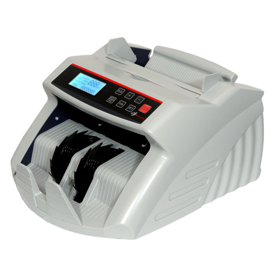
Bankomat cash counting machine
4. Batch Counting and Adding Features
Batch counting capabilities enable users to set the machine to count a specific number of notes and stop automatically, which is useful for preparing cash for deposits. Some machines also offer adding features, allowing you to accumulate totals from multiple batches, enhancing the overall cash management process.
5. User-Friendly Interface
An intuitive and easy-to-use interface is essential for minimizing training time and reducing errors. Look for machines with clear displays, straightforward controls, and features like automatic start/stop functions. A user-friendly design ensures that staff can operate the machine efficiently without extensive training.
6. Versatility in Handling Different Denominations
Some note counting machines can recognize and sort different denominations automatically. This feature is particularly beneficial for businesses that deal with mixed currency, as it simplifies the counting and reconciliation process. Machines that can handle both old and new notes are also advantageous, ensuring compatibility with various currency types.
Conclusion
Choosing the right note counting machine involves evaluating these key features to ensure it meets your business needs. By focusing on counting speed, counterfeit detection, hopper size, batch counting capabilities, user-friendliness, and versatility, you can select a machine that enhances your cash management processes and reduces the risk of errors and losses.
#bankomatautomationprivatelimited#cash counting machine#cashdrawer#laminationmachine#papershader#billingmachine#notecountingmachine#currencycountingmachine#safelocker
1 note
·
View note
Text
Methods for optimizing the performance of hybrid stepper motors
1.Definition of hybrid stepper motors Hybrid stepper motors are designed by combining the advantages of permanent magnet stepper motors and reactive stepper motors. Through a specific structural design, it achieves the complementary advantages of high torque of permanent magnet stepper motors and high precision of reactive stepper motors. Hybrid stepper motors are divided into two-phase, three-phase and five-phase, of which the step angle of two-phase is generally 1.8 degrees, the step angle of three-phase is generally 1.2 degrees, and the step angle of five-phase is generally 0.72 degrees. The rotor of this motor is magnetic, so the torque generated under the same stator current is greater than that of reactive stepper motors. In addition, the step angle of hybrid stepper motors is usually small, which makes it widely used in economical CNC machine tools. Although the structure of the hybrid rotor is more complex, the rotor inertia is large, and its speed is lower than that of the reactive stepper motor, its high precision and high torque characteristics make it the preferred choice in many applications.
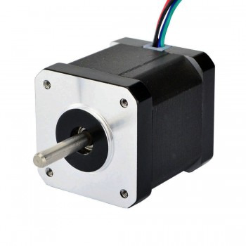
2.Installation requirements for hybrid stepper motors 1.Determine the installation location: First, you need to choose a suitable location for installation based on the actual needs and space limitations of the equipment. At the same time, you must also consider the connection method and location of the stepper motor and other components (such as transmission devices, sensors, etc.) to ensure stable installation and normal operation. 2.Connect the power supply and controller: Before installing the stepper motor, you need to connect the power supply and controller correctly. Stepper motors are usually powered by a DC power supply, and you need to pay attention to the matching of voltage and current to ensure the stability and safety of the power supply. 3.Install the driver and controller: The motion control of the stepper motor is achieved through the driver and controller. The driver converts the current signal provided by the power supply into a control signal that the stepper motor can accept, while the controller is responsible for giving the corresponding step pulse signal. During the installation process, the driver and controller need to be correctly installed on the equipment and connected to the stepper motor according to the wiring diagram. 4.Connect external devices: According to actual needs, the stepper motor may need to be connected to some external devices, such as sensors, encoders, etc. These devices can provide feedback signals to help control the movement of the stepper motor and improve control accuracy and stability. During the installation process, it is necessary to ensure that these external devices are connected to the stepper motor and controller normally, and the signal transmission is correct. 5.Perform basic debugging and fine debugging: After the installation is completed, perform basic debugging on the stepper motor, check whether the power supply and controller are normal, and ensure that the circuit connection is correct. Then, send a pulse signal to the stepper motor through the controller, observe the movement of the stepper motor, and check whether there is any abnormality. After the basic debugging is completed, some fine debugging work can be performed to improve the performance and control accuracy of the stepper motor.
3.Cooling method of hybrid stepper motor 1.Air cooling: Increase the air flow around the motor by installing a fan or heat sink to accelerate the dissipation of heat. This method is suitable for situations where the motor capacity is not very large. Through the fan-type radial and axial mixed ventilation system, the motor temperature can be effectively reduced. 2.Liquid cooling: Set up a liquid cooling system inside the motor to transfer the heat inside the motor to the outside through liquid to accelerate the dissipation of heat. This is a very effective heat dissipation method, mainly used in occasions that require long-term continuous work. 3.Hydrogen cooling: Make the rotor and stator wires hollow, then compress the hydrogen and compress it into the conductor to take away the heat. Hydrogen cooling is more effective than air cooling, but it may be more complicated to implement. 4.Current reduction method: Reduce the heat generated by the motor by reducing the drive current of the stepper motor to achieve the purpose of heat dissipation. This method is suitable for situations where the performance requirements of the motor are not particularly high. 5.Optimize the design structure: By optimizing the design structure of the stepper motor, the heat generation inside the motor can be reduced, thereby reducing the temperature of the motor. This includes improving the material selection of the motor, optimizing the magnetic field design, etc. 6.Environmental control: Reduce the operating temperature of the motor by controlling the ambient temperature, reducing the motor load, reducing the motor current, etc., thereby reducing the heat generation. This method is suitable for situations where you have control over the working environment of the motor.
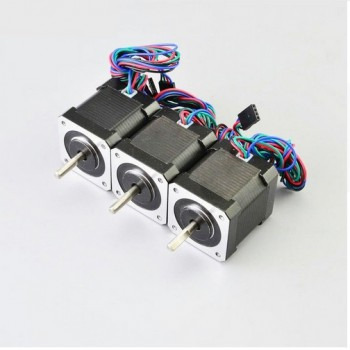
4.Methods for optimizing the performance of hybrid stepper motors 1.Adopt a new generation of controllers, introduce more advanced controllers, provide more precise step angle control and higher control accuracy. 2.Optimize the drive system, improve the motor drive circuit, and improve the power transmission efficiency and motor response speed. 3.Introduce a closed-loop control mechanism, adjust the rotation speed and position of the stepper motor in real time through the feedback mechanism, and improve the motion accuracy. 4.Improve the motor structure, optimize the design and material selection of the stepper motor, and reduce noise and vibration. 5.Provide more interfaces, increase communication interfaces and control options, and facilitate the integration of stepper motors with other devices. 6.Use finite element analysis for optimization design, analyze the electromagnetic field, temperature field, vibration, etc. of the stepper motor, and optimize the motor design. 7.Reduce the moment of inertia. Reducing the moment of inertia of the stepper motor can increase the response speed of the motor, thereby improving its dynamic performance. 8.Add overload protection. Adding overload protection to the stepper motor can prevent the motor from overloading, thereby protecting the motor from damage. 9.Optimize the motor material. Selecting the right material can increase the efficiency, stiffness and durability of the motor. 10.Improve the cooling system. A more efficient cooling system can prevent the stepper motor from overheating, thereby improving its reliability.
In addition, the performance of the hybrid stepper motor can be further improved by using micro-stepping drives to increase the resolution of the stepper motor, using high-precision magnets and winding materials, and optimizing control algorithms. These methods can be selected and combined according to specific applications and requirements to optimize the performance of the hybrid stepper motor.
0 notes