#full wave bridge rectifier
Explore tagged Tumblr posts
Visit Tumblr Blog
Explore Tumblr blogs with no restrictions, modern design and the best experience.
Last Seen Tumblr Blogs


Fun Fact
Tumblr has been providing a Korean-language service since 2013.
Text
Semikron SKD160-16 Bridge Rectifier Diode: High-Power Solution for Industrial Applications
For more information or to purchase the SKD160-16, visit the official website of Semikron distributor https://www.uscomponent.com/buy/Semikron/SKD160-16.
With its combination of high surge current capability, rugged design, and high efficiency, the Semikron SKD160-16 Bridge Rectifier Diode offers reliable performance in even the most demanding industrial environments. Its compact yet durable package ensures it can withstand harsh conditions while delivering consistent and efficient power conversion.
By choosing the Semikron SKD160-16, you benefit from a trusted solution for high-power applications that demand efficiency, reliability, and durability.
SKD160-16 is a high-power Bridge Rectifier Diode produced by Semikron, a leading manufacturer of power electronics components. It is designed for use in high-current applications and is widely used in power supplies and industrial automation systems.
The SKD160-16 Bridge Rectifier Diode is a four-terminal device consisting of four diodes that are arranged in a bridge configuration. This configuration allows for the conversion of an alternating current (AC) input signal to a direct current (DC) output signal.
The diode has a maximum current rating of 160A and a maximum voltage rating of 1600V, making it suitable for high-power applications. It is also designed with a high surge current capability, which enables it to handle brief overloads without damage.
The SKD160-16 Bridge Rectifier Diode is designed with low forward voltage drop and low reverse recovery time, which results in low power dissipation and high efficiency. It is also designed with a rugged and reliable package, which provides excellent thermal performance and high resistance to mechanical stress.
Overall, the SKD160-16 Bridge Rectifier Diode is a high-performance device that provides efficient and reliable power conversion capabilities in high-power applications. Its rugged design and high surge current capability make it suitable for use in harsh environments and industrial applications that require high reliability and durability.
#Diode#Bridge Rectifier#Transistor#Full Wave Bridge Rectifier#Bridge Rectifier Diode#High Current Bridge Rectifier#High Power Bridge Rectifier#Module Transistor#Transistor Module#SKD160-16#Semikron SKD160-16#Semikron Authorized Distributors#Semikron Distributor
0 notes
Text
Full Wave Bridge Rectifier: Circuit Diagram, Working and Its Types

Hello Friends! Today, we are going to cover all possible things about what is full wave bridge rectifier; involving its circuit diagram along with their working operations and types with ease. This is unique article over the internet; so making ensure that at the end of this post; you will definitely completely understand about Full Wave Bridge Rectifier without getting any hindrance.
Bridge Rectifier Tutorial Headlines:
In this section, we will show you all headlines about this entire article; you can check them as your choice; below shown all:
What is Bridge Rectifier?
Bridge Rectifier Circuit Construction
Bridge Rectifier Working Principle with Operations
Characteristics of Bridge Rectifier
Types of Bridge Rectifiers
Applications of Bridge Rectifiers
Advantages of Bridge Rectifiers
Disadvantages of Bridge Rectifier
FAQs (Frequently Asked Questions)
What is Full Wave Bridge Rectifier (FWBR) and its types?
What is the ripple factor in a Full Wave Bridge Rectifier?
How is the output voltage calculated in Full Wave Bridge Rectifier?
Can Full Wave Bridge Rectifiers be used for high voltage applications?
What is the difference between a Full Wave Bridge Rectifier and a Center-Tap Full Wave Rectifier?
How can the efficiency of a Full Wave Bridge Rectifier be improved?
Let’s Get Started!!
0 notes
Text
Rectifiers play a crucial role in converting AC to DC, making them essential in various electrical and electronic applications. In this video, we cover: ✅ What are rectifiers? ✅ Types of rectifiers (Half-wave, Full-wave, Bridge) ✅ Working principles explained ✅ Key applications in industries
📌 Watch now to gain in-depth knowledge!
📢 Read more here: https://www.emcoprecima.com/blog/understanding-rectifiers-types-working-principles-and-applications/
0 notes
Text
Unleash Maximum Efficiency with Three-Phase Rectifiers

In a world where power systems are the backbone of industry, the importance of efficient energy conversion cannot be overstated. Enter the three-phase rectifier, a marvel of engineering that takes alternating current (AC) and converts it into direct current (DC) with remarkable efficiency. Whether you're powering industrial machinery, electric motors, or sophisticated electronics, these rectifiers ensure you get the most out of your energy source.
What is a Three-Phase Rectifier?
A three-phase rectifier is a device used to convert AC power from a three-phase source into DC power. By leveraging three alternating phases, these rectifiers provide a smoother and more reliable DC output compared to single-phase systems.
Among its variants, the three-phase bridge rectifier and three-phase full wave rectifier are the most commonly used configurations, delivering robust performance across a wide range of applications.
How Do Three-Phase Rectifiers Work?
The magic of three-phase rectifiers lies in their use of diodes to manipulate AC current. The three-phase diode bridge rectifier, for instance, employs six diodes arranged in a bridge configuration. These diodes allow current to flow in a single direction, transforming the three-phase AC input into a constant DC output.
Key Benefits:
High Efficiency: Minimal power loss during conversion.
Smooth Output: Reduced ripple for consistent DC power.
Reliable Performance: Handles heavy loads with ease.
Applications of Three-Phase Rectifiers
From industrial setups to renewable energy systems, the versatility of three-phase rectifiers makes them indispensable. Some key applications include:
Industrial Machinery: Powering large-scale motors and drives.
Welding Equipment: Ensuring stable energy for precision tasks.
Renewable Energy: Converting power from wind turbines and solar arrays into usable electricity.
Electric Vehicles: Supporting battery charging systems.
Why Choose a Three-Phase Rectifier?
When it comes to efficiency, reliability, and power, nothing beats the performance of a three-phase full wave rectifier or a three-phase bridge rectifier. Their ability to handle high loads, deliver consistent output, and operate with minimal energy loss makes them a top choice for demanding applications. Switch to three-phase rectifiers and take your power systems to the next level. Experience the perfect balance of innovation and performance as you unleash maximum efficiency in your operations!
0 notes
Note
tell me everything about AC to DC filters Right Now
:0
Dear god.
OK I have to make some assumptions or else this is going to get really long. I am going to assume that you already know what AC and DC are. I am going to assume that you took (and passed) geometry, so a sine wave and it's variations are familiar to you. I am also going to assume that you also know the difference between voltage, current, and resistance.
So, what are AC to DC, why do we care about that? Well, the electricity coming out of the wall is AC, but in order to, lets say, charge your laptop battery, you need DC. In fact, if you look at a laptop charger, you'll see The Brick. The thick rectangle that gets hot when charging the laptop.
THAT'S THE AC TO DC CONVERTER
I just called it converter instead of filter. Why? Because filters technically only remove a 'ripple' from DC current, so a current that's almost DC but not quite. If you are making the entire jump from AC to DC, then that's called a converter.
Now here's where things get fucked.

These are all of the parts after the plug. The load is your laptop, the regulator is your filter.
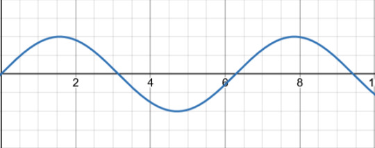
Let's say that this is your AC signal (this graph showing the voltage over time). Now, the first thing this passes through is the transformer, which only adjusts the voltage to the correct level. Some devices need it higher, some lower. Let's say that this transformer is a step up transformer, because it made the signal bigger.

The next step is the rectifier. Now, traditionally this part is taught in stages in order to show it's affect on the signal. I'm going to speed run that. I will assume that you're familiar with what a diode is. If you aren't, just know that it only allows current to flow in one direction. So, anything going backwards will be removed. Picture a one way valve.
So, if we were to send this signal through one diode, then that would leave us with
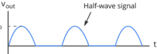
just the positive half! That's why this setup is called a Half-wave rectifier.
But what if we were to use two diodes. As in, fill in the blank spot that the negative half left with another positive bump. That would give us

This lovely thing! Which is great, but it requires another AC signal that is 180 degrees off from the original one in order to exist. Which, transformers exist which can provide that, but it's not cost effective. So, that leaves us with the most common setup, the Bridge Rectifier.
I've been skipping the circuit diagram so far, but now it's important.
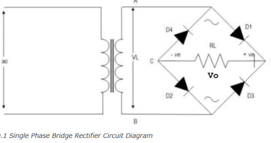
THIS thing is a bridge rectifier connected to the transformer (yes that's what transformers look like according to circuit diagram shorthand). Now, I am American, and for some reason American electricians use that up and down sharp thing in the middle of the diamond to indicate a resistor. Europe uses a rectangle. Again, I am going to assume that you know what a resistor does.
Those four black triangles with lines? Those are diodes. The line across the tip of the triangle indicates what direction they are allowing current to flow into. Now picture you were a positive signal flowing in through point A into the bridge. There's a split in the circuit, but one way (diode D4) is blocked, so you have to go across diode D1. Now you're at the edge of the diamond, once again two ways you can go. You head towards diode D2, because diode D3 won't let you through. What that looks like is this
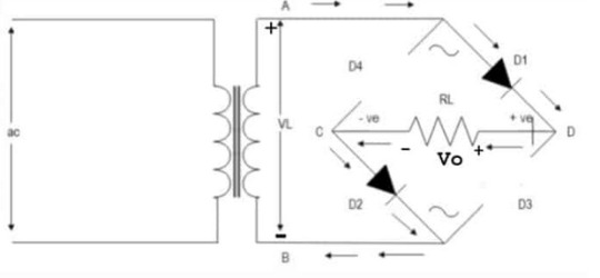
What about the other direction? Well that looks like
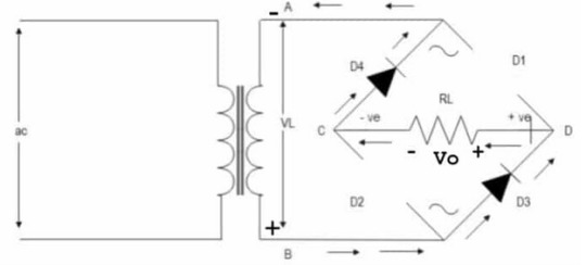
Notice that the edges of the diamond are called out? Points C and D. That's the money makers. You see, if you plug into point D as your positive and C as your negative, you get a full wave signal! (so sorry for not going fully in depth on why that works just trust me it's a bit of a mess and should really be taught with the actual circuit in front of you, not across the internet like this)
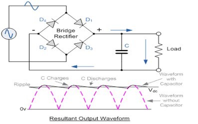
A full wave signal is completely positive, but it's not exactly DC yet. That's where smoothing comes in. This is done with a capacitor!

The capacitor is charged up and then slowly releases it's charge. But before it can completely discharge, it gets recharged by the next wave. Quick review, a capacitor is like a battery where it can be charged up, but unlike a battery which holds charge with chemistry, capacitors hold charge with physics. They can still wear out, but not nearly as quickly as a battery.
What does that red line look like? Well, almost like a straight line, except it has RIPPLES! That's right, we're finally back to the filter! Or the regulator as the diagram calls it. Means the same thing.
Sometimes, this step is skipped. If the device getting signal isn't too sensitive or it's just cheep, then the electricity stays bouncy. Some devices really care about any fluxuation in the signal, in which case they get a big expensive filter.
Unfortunately, the inner bits of a filter are many, so I won't be going into all of that. But you want me to go into that, so I will show a circuit diagram.
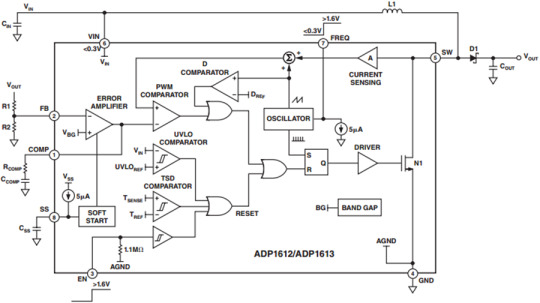
This is a diagram of the ADP1612
This website has a downloadable version of the spec sheet!
But that's a level of detail that you usually only get into if you are planning on building a circuit. The day that you're flipping through spec sheets in order to check compatibility is when you've really become an engineer.
So that's how you go from AC into DC. Yes, I just spent an hour typing this all out. I like electricity a lot.
Here's a GREAT video that goes over all of this but the guy actually has a circuit and an ossiliscope in front of him to show the signal.
#electricity#electronic#electrical engineers#physics#AC to DC rectifier#electrical engineering#mmm electricity for power#ask#literally several college classes worth of info that I am skipping in this#ough my circuit bits#I chose the perfect degree I am built for this shit
11 notes
·
View notes
Text
That's a full wave bridge rectifier. It's a (now somewhat outdated in most applications) method of getting a steady DC (or DC-ish) current from an alternating current. The transformer to the left of the diagram (basically two big coils of wire with a specific number of loops relative to each other) gets used to step an AC voltage up or down to a peak voltage a little above the final desired DC voltage. Then the diode circuit on the right has the effect of letting the positive part of the wave through and inverting the negative part of the AC sine wave.
Paired with a capacitor and a voltage regulator, you can get a pretty clean DC voltage out the other side with a well-designed rectifier.
But we tend to use a more modern circuit design now, which doesn't require the big, bulky transformers used in linear power supply circuits like the above. The new ones still need a transformer, but it can be much smaller. That's why phone chargers and other chargers got so much smaller and lighter recently — there's just a lot less copper wire inside.
And not to burst any bubbles, but in practice, rectifier circuits aren't physically laid out like the diagrams. Here's one, with the capacitor, but without the transformer component. That would get hooked up to two of the screw terminals, and the other two are the DC output.

i unironically believe electricity is the closest thing we have to magic in this universe. consider:
it's basically what human "souls" are made of (your consciousness is the result of miniscule amounts of electric charge jumping between neurons in your brain)
when handled incorrectly or encountered in the wild, it is a deadly force that can kill you in at least half a dozen different ways
when treated respectfully and channeled into the proper conduits, it is a power source that forms the backbone of modern society
if you engrave the right sigils into a rock and channel electricity into it, you can make the rock think
there is a dedicated caste of mages (electrical engineers) tasked with researching it in ivory towers
whatever the fuck Galvani was doing with those frog legs
look at this and just try to tell me it isn't a kind of summoning circle

52K notes
·
View notes
Text
AC-DC Rectifier: Bridging Two Worlds of Power
Imagine a world without electricity conversions — where your laptop won’t charge, your phone stays dead, and industrial motors fail to operate. Unthinkable, right? What stands between AC power from the grid and your DC-powered electronics is an essential, often invisible device: the AC-DC Rectifier.
Despite being critical to everything from daily gadgets to complex aerospace systems, the rectifier rarely gets credit for the massive transformation it enables. Let’s change that.
From Alternating to Direct – Why It Matters
Alternating Current (AC) is how electricity travels through our power grids. It’s efficient for long-distance transmission, easy to step up or down in voltage, and suitable for large-scale energy distribution. However, most electronics — your smartphone, LED lights, electric vehicles, and even high-end servers — run on Direct Current (DC).
So how do we bridge this gap?
Enter the AC-DC Rectifier, the vital converter that transforms grid-fed AC into usable DC. It’s not just about electricity; it’s about adaptation — evolving the flow of energy to meet the needs of technology. And in that transformation lies an intricate blend of science, design, and application.
A Story You Can Relate To
Meet Priya, an electrical engineer at a solar microgrid company in Rajasthan. Her challenge wasn’t lack of solar energy; it was inconsistent performance from stored power. The culprit? Cheap, inefficient rectifiers that distorted the signal and degraded batteries.
When Priya introduced industrial-grade AC-DC Rectifier modules with controlled ripple and thermal protection, battery life improved by 30%, and the system uptime went up dramatically. What seemed like a simple switch turned out to be a major performance boost — something her team hadn't fully anticipated until they saw it in action.
The rectifier wasn’t just a component anymore — it was an enabler.
The Tech Under the Hood
So how exactly does an AC-DC Rectifier work?
At its core, rectification involves converting a sinusoidal AC wave into a linear DC line. This is achieved through the use of diodes, thyristors, or MOSFETs, depending on complexity and application.
1. Half-Wave Rectification
Only the positive half of the AC signal is allowed to pass through. It’s simple, but inefficient and used only in low-demand circuits.
2. Full-Wave Rectification
Both halves of the AC waveform are utilized. With the help of bridge rectifiers, the output is more consistent, ideal for higher-power applications.
3. Controlled Rectifiers
These use semiconductor devices like SCRs or IGBTs, allowing engineers to control output voltage levels — essential for motor speed controllers and battery chargers.
4. Filtered Rectifiers
To reduce “ripple” — the leftover wave-like behavior in DC — capacitors and inductors are added to smooth out the flow.
Each rectifier type serves different needs, from tiny phone chargers to complex power supplies in industrial automation.
Why It Matters More Than Ever
The rise of DC-based technologies makes AC-DC Rectifier systems even more critical today than they were a decade ago.
1. Electric Vehicles (EVs)
Charging stations rely heavily on rectifiers to ensure batteries receive pure, stable DC. A poor rectifier can shorten battery life and reduce driving range.
2. Renewable Energy
Solar panels generate DC, but many systems need AC to interface with the grid — and vice versa. Modern energy systems use rectifiers to maintain voltage stability.
3. Data Centers
Servers operate on DC. Rectifiers convert incoming AC to keep massive infrastructure running smoothly — a split-second glitch can cause thousands in downtime.
4. Medical Devices
Precision instruments like MRI machines or ventilators require pure, distortion-free DC. This level of quality is only possible through specialized rectifiers.
Humanizing the Current
Let’s not reduce this technology to circuits and silicon. The AC-DC Rectifier is a guardian of stability. When you’re working late on a presentation, your laptop humming reliably — thank the rectifier. When hospitals maintain life-support systems during a blackout with the help of inverters and UPS systems — thank the rectifier. When satellites silently collect data while orbiting Earth — again, thank the rectifier.
It doesn’t just convert voltage; it converts possibilities into realities.
The New Era of Smart Rectifiers
Thanks to advancements in power electronics, today’s rectifiers are smarter, more efficient, and application-specific.
Wide Bandgap Semiconductors (SiC, GaN): They allow for faster switching, higher temperatures, and smaller components. Great for high-frequency and aerospace applications.
Digital Control Systems: Feedback-based systems help monitor current, correct fluctuations, and adjust to real-time demand.
Energy Recovery: Some modern rectifiers are designed to push unused energy back into the grid or battery systems.
Modular Rectifier Systems: Ideal for scaling power supplies. Need more output? Just plug in another rectifier module.
Tips When Choosing an AC-DC Rectifier
Whether you're an engineer, project manager, or someone setting up a high-powered system, here’s what to consider:
Power Rating: Match it to your load requirements.
Input Voltage Range: Ensure flexibility for different global standards.
Efficiency (>90%): Better efficiency means less heat and lower power bills.
Thermal Management: Good rectifiers come with built-in cooling or heat sink options.
Certifications: UL, CE, or ISO depending on the region and industry.
EMI Filtering: Reduces interference in sensitive systems.
Redundancy Features: In mission-critical applications like healthcare or aviation, dual rectifiers with automatic failover are a must.
Final Thoughts: More Than a Converter
The next time you plug in a charger, boot up a server, or admire an EV silently gliding past, remember — an AC-DC Rectifier is working behind the scenes. It's the bridge between chaotic currents and calm, directed energy. It's not just about volts and amps; it's about reliability, precision, and trust.
If you're building or maintaining systems where power matters — give the rectifier its due importance. Because in a world that runs on conversions, AC-DC Rectifier technology is the unsung foundation of modern energy infrastructure.
0 notes
Text
Full wave bridge rectifier
I have experience in knowingabout; Standard Rectifiers, MRA4004T3G, onsemi, recovery rectifier diode, and Full wave bridge rectifier.
0 notes
Text
What Does a Rectifier Do?
Introduction to Rectifiers
A rectifier is an essential electrical device that converts alternating current (AC) to direct current (DC). AC power fluctuates in polarity, making it unsuitable for devices requiring a steady voltage. Rectifiers ensure a one-directional flow of current by blocking the negative half of the AC cycle or converting it entirely. They are widely used in power supplies, electronic circuits, and battery charging applications. Depending on the configuration, rectifiers can improve efficiency, reduce power losses, and provide stable DC output essential for various electronic and industrial applications.
Types of Rectifiers
Rectifiers come in different types based on their design and operation. The most common are half-wave, full-wave, and bridge rectifiers. A half-wave rectifier allows only one half of the AC cycle to pass, while a full-wave rectifier utilizes both halves, providing better efficiency. Bridge rectifiers, a type of full-wave rectifier, use four diodes to maximize current conversion with minimal power loss. The choice of rectifier depends on application requirements such as voltage stability, efficiency, and ripple factor.
Working Principle of a Rectifier
Rectifiers function using diodes, which allow current to flow in only one direction. In a half-wave rectifier, a single diode blocks one-half of the AC cycle, producing a pulsating DC output. Full-wave rectifiers, whether center-tap or bridge type, use multiple diodes to rectify both halves of the AC waveform, resulting in smoother DC output. The rectified signal often requires filtering through capacitors or inductors to reduce voltage fluctuations and improve performance in sensitive electronic circuits.
Applications of Rectifiers
Rectifiers are integral to many electrical and electronic systems. They are used in power supplies for household appliances, industrial machinery, and communication systems. Battery chargers employ rectifiers to convert AC power into DC for recharging. In automotive applications, rectifiers regulate voltage in alternators to provide stable power to vehicle electronics. Additionally, they play a crucial role in renewable energy systems, converting AC generated by wind turbines and solar inverters into usable DC power.
Advantages and Limitations
Rectifiers offer numerous advantages, including efficient AC-to-DC conversion, low power losses, and reliable performance in various applications. Bridge rectifiers, in particular, provide higher efficiency by utilizing both halves of the AC cycle. However, rectifiers also have limitations, such as voltage ripple, which requires additional filtering components for smooth DC output. Power dissipation in diodes can lead to heat generation, necessitating heat sinks in high-power applications. Despite these challenges, rectifiers remain indispensable in modern electrical and electronic systems.
0 notes
Text
Sent the top picture to my father, a physics enjoyer, who proceeded to inform me that "what the fuck" is a mercury vapor rectifier, and the diamond shape in "THEY ARE NOT RUNES SHUT UP" is the "FULL WAVE BRIDGE RECTIFIER" (in all caps for some reason?). He also sent me videos of/about both of them.
So anyway, this stuff is totally real science!

#i can not stress enough how much i enjoy when people can identify random things to me#delightful#tell me more
119K notes
·
View notes
Text
SanRex CVM75BB160 Bridge Diode Rectifier
CVM75BB160 is a high-power bridge rectifier diode designed for use in high-voltage and high-current applications. It is a four-terminal device that consists of four diodes arranged in a bridge configuration. This allows the diode to convert an alternating current (AC) input signal into a direct current (DC) output signal.
The CVM75BB160 diode is housed in a compact and rugged module that is designed for easy mounting and high reliability. The module is constructed using a high-temperature, thermally conductive material that allows for efficient heat dissipation. The diode module is rated for a maximum peak reverse voltage of 1600V and a maximum average forward current of 75A.
The CVM75BB160 diode module has low forward voltage drop and low leakage current, which results in high efficiency and low power dissipation. The module also has a high surge capability, which makes it suitable for use in applications with high transient overloads. The diode module has a built-in snubber circuit that reduces voltage spikes and transients, protecting the diode from damage and increasing the module's overall reliability.
Overall, the CVM75BB160 bridge rectifier diode module is a high-performance and reliable component that is widely used in power supply, motor control, and other high-current applications. Its compact and rugged design, high surge capability, and built-in protection features make it an ideal choice for demanding industrial and commercial applications.
#Diode#Bridge Rectifier#Full Wave Bridge Rectifier#Bridge Rectifier Diode#High Current Bridge Rectifier#High Power Bridge Rectifier#SanRex CVM75BB160#SanRex Rectifier#Rectifier SanRex#CVM75BB160#Diode Module#SanRex#CVM75BB160 Datasheet#SanRex Diode Module#SanRex Distributor#SanRex Diode
0 notes
Text
PE 400/150/5 Protective Element for Enhanced Rectifier Performance
Discover the PE 400/150/5 protective element from Emco Precima, designed to connect parallel to rectifiers BGL, EGL, and SGL, enhancing interruption capacity with EMC compatibility and integrated spark quenching.
For more information visit our website: https://www.emcoprecima.com/
0 notes
Text
If anyone's wondering why they flicker, it's cost and physics.
Leds are a form of diode, born when researchers noticed that glass diodes had a faint glow. Diodes help turn ac into dc, a sort of one way valve for electricity.
Dc works fine with diodes. Ac reverses polarity half the time, thus half the time, the diode blocks the power. Thus, half the time, power would cut out. Half in this case is 60 times a second (or 50 in other regions), as 60hz means that 60 times a second a sine wave completes it's rotation.
But humans figured out how to fix this immediately. A full bridge rectifier turns both the negative and positive parts of the ac current into just positive, which the LEDs like. Diodes are now, in fact, dirt cheap and tiny. Hell, you can buy full bridge rectifiers for dirt cheap pre-made. It's pennies on the dollar. If you really want cheap, they could go for a full wave rectifier.
And a capacitor. think of a capacitor as a mini rechargeable battery, delivering continuous power, smoothing out the peaks of a sine wave.
But it's down to just 4 more diodes (or two) and a capacitor. Which are, like i said, dirt cheap.


This is one of those things where the discourse is just completely broken. Both of these takes are shit and no one is concerned about the actual problem.
Republicans want to bring back incandescents because they just want to trigger the libs and have decided light bulbs are woke.
And the "LEDs are fine" crowd are throwing people with flicker sensitivities under the bus. And, no, you don't have to be "pretty far on the spectrum" to notice a difference. And even if you did... why in the world is this person so dismissive of the millions of autistic folks?
LEDs, for the most part, are superior to incandescent bulbs. Collectively they save people billions of dollars in energy costs and greatly reduce fossil fuel use. You have more options for color and brightness. You can control them with your phone. LEDs are fantastic.
Unfortunately there is a design flaw that makes LEDs hard to use for certain people. Due to AC power, most LEDs have a 60hz refresh rate. Meaning they turn off and on 60 times per second. With incandescents this didn't matter because the filament didn't have time to lose its glow between cycles.
Most people cannot see this flicker in LEDs. But there are millions of people who are sensitive to it and it can cause migraines and discomfort.
The solution is definitely not to go back to incandescents. There are flicker free LEDs and I think with some regulation we could make sure all LEDs are flicker free or at least make sure flicker free bulbs are easy to find and not priced at a premium.
Thankfully there is a group testing bulbs to find the ones that will most likely cause no discomfort. They call themselves the Flicker Alliance and their website has a pretty decent selection of tested and approved bulbs.
So if you feel like your LED bulbs might be causing you distress, that is a good resource to try. I think there is also something you can do to make sure the LED drivers are using DC power, but I haven't really looked into that.
9K notes
·
View notes
Text
A simple DIY guitar tremolo pedal
Have you ever thought of making your guitar sound differently or just livening things up a bit? In addition to reverb and chorus, a subtle tremolo can help. Today, I will build a very simple tremolo pedal using three transistors.

Of all the time-based effects, electronic tremolo is the easiest to get.
The important thing is that one does not need to alter amplifier bandwidth for tremolo, like in wah pedals and phasers, by electronically reconfiguring frequency-dependent circuits containing active and reactive resistances—resistors, coils, and capacitors.
There is no need to implement, much less modulate, the signal time delay. This is done in delays, reverbs, flangers, and choruses using mechanical, analog (bucket brigade devices, BBD), and digital delay lines.
Moreover, there is no need to process the frequency of the input signal. Raising the frequency by an octave is relatively simple; it takes a full-wave rectifier, similar to those used in power supply units.

A full-wave rectifier folds the wave. It turns the lower half-wave up, and now there is a whole period of the output signal for each half-cycle of the original signal.
We have doubled the fundamental frequency and added some harmonics. After all, the output signal is no longer sine. The upper half-wave is smooth, and the lower half-wave is pointy.
The first octave did not use a bridge rectifier with four diodes but a half-bridge rectifier with two diodes and a transformer with the winding having a midpoint.
Such a transformer was easy to find. For example, a phase-inverter matching transformer from a pocket transistor radio could do. We've put together a receiver of this kind in a post about the Regency TR-1.

It is unnecessary to use a transformer if you build a full-wave rectifier using operational amplifiers.

And finally, when making a phase inverter for a full-wave rectifier, you can do it without operational amplifiers. One transistor is enough. After all, the output signal at its emitter has the same polarity as the input signal at the base, and at the collector, it has inverted polarity.

Suppose the signal frequency needs to be decreased by half, not increased. In that case, that is, by one octave, then synchronous D-flip-flops, which we've discussed in previous articles, will be helpful.

A circuit divides the oscillator frequency on a 555 timer by 2, 4, 8, and 16. That is, by two to the first, second, third, and fourth powers. And if we speak musical terminology, we lower the tone by one, two, three, and four octaves.
However, electric guitar pickups do not produce digital pulses or even a sine wave but an analog signal of a complex shape with many harmonics. So, to divide the frequency with flip-flops, the guitar signal must be preprocessed by converting it into rectangular pulses.
One possible circuitry answer to this problem is in the diagram of this old Japanese pedal. Here, the signal on its way to the latches passes through a compressor and a Schmitt trigger.

The compressor is needed to process both loud and quiet notes effectively. Interestingly, the CMOS NAND gate circled in green on the diagram, is used as an analog signal amplifier.
This is doable. The ratio of the resistor value between the output and the inverting input of the CMOS inverter to the impedance in series with the input determines the gain, just like in an operational amplifier.
An excellent example of a pedal that uses CMOS inverters rather than transistors, op-amps, or tubes to amplify the guitar signal is the Tube Sound Fuzz circuit, designed by Craig Anderton and published in his 1975 book "Electronic Projects for Musicians."

Frequency dividers on flip-flops work well with a single note. And for a chord or pitch shifting at an interval of a non-integer octave number, a digital signal processor is almost always required.
Perhaps the only exception is the perfect fifth. The original frequency must be divided by three and multiplied by two to obtain it. Frequency division into three is possible using a single CD4013 chip containing two synchronous D-flip-flops with asynchronous setup and reset.

At each of the points of the circuit, marked with numbers 2, 3, and 4, there is a frequency from point 1, divided by 3, in the form of a PWM signal with a duty cycle of 2/3 or 1/3. For music, this sounds even better than a duty cycle of 1/2.
The phases of the signals at these points are shifted between each other, which can also be used for interesting sound effects. But there is one problem.
Modern music uses not natural but evenly tempered tuning. Therefore, our electronic fifth, played by flip-flops, will be slightly out of tune relative to the fifth on the guitar frets.
The frequency of this equal-tempered fifth is not equal to two-thirds the frequency of the original note but to the frequency of the original note divided by the 12th root of 128. This system allows one to freely transpose melodies and chord progressions from one key to another. That is why it became universally recognized.
And to get a tremolo, you don’t need all these tricks. Two functional blocks are enough: LFO and VCA, a low-frequency oscillator, and a voltage controller amplifier.
Each of them can be implemented literally on one transistor. This is precisely what the developers of the Univox/Unicord U65RN combo amplifier, produced since 1971, did.
Frequency dividers on flip-flops work well with a single note. And for a chord or pitch shifting at an interval of a non-integer octave number, a digital signal processor is almost always required.
Perhaps the only exception is the perfect fifth. The original frequency must be divided by three and multiplied by two to obtain it. Frequency division into three is possible using a single CD4013 chip containing two synchronous D-flip-flops with asynchronous setup and reset.
At each of the points of the circuit, marked with numbers 2, 3, and 4, there is a frequency from point 1, divided by 3, in the form of a PWM signal with a duty cycle of 2/3 or 1/3. For music, this sounds even better than a duty cycle of 1/2.
The phases of the signals at these points are shifted between each other, which can also be used for interesting sound effects. But there is one problem.
Modern music uses not natural but evenly tempered tuning. Therefore, our electronic fifth, played by flip-flops, will be slightly out of tune relative to the fifth on the guitar frets.
The frequency of this equal-tempered fifth is not equal to two-thirds the frequency of the original note but to the frequency of the original note divided by the 12th root of 128. This system allows one to freely transpose melodies and chord progressions from one key to another. That is why it became universally recognized.
And to get a tremolo, you don’t need all these tricks. Two functional blocks are enough: LFO and VCA, a low-frequency oscillator, and a voltage controller amplifier.
Each of them can be implemented literally on one transistor. This is precisely what the developers of the Univox/Unicord U65RN combo amplifier, produced since 1971, did.
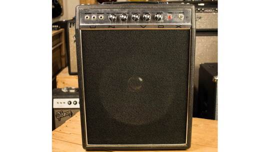
It had 15 watts of power, a 12-inch loudspeaker, and a spring reverb. It was assembled according to a relatively simple circuit by today's standards. However, at that time, it was considered quite complex.

Our attention should be drawn to the lower left corner, which shows the tremolo diagram. The leftmost transistor is used in the phase-shifting RC LFO. This generator produces harmonic sine waves, the frequency of which is controlled by the SPEED potentiometer.
Oscillations from the LFO output go to the modulation intensity control INT and to the second transistor's base. This transistor simply bypasses all input signals from the microphone, guitar, and organ. This is how the VCA is made.
And the tremolo pedal jack simply shorts the LFO signal to the ground, and the VCA transistor is completely turned off. This allows one to turn the tremolo on and off using a pedal with just a latching SPST button inside.
The diagram published by Anthony Leo in the November 1968 issue of Electronic Australia Magazine, 3 years before the Univox/Unicord U65RN, differs slightly from the tremolo found in this combo amp.
Since then, the circuit has been called the Electronic Australia tremolo or EA tremolo for short. It's a beloved one among pedal enthusiasts.

Here, the VCA comprises a common-emitter bipolar transistor Q1 and a JFET Q2 that bypasses most of Q1's AC bias resistance, thereby modulating the stage's gain.
I've assembled this DIY pedal kit from Landtone using just this scheme. In the video below, you can hear the resulting sound.
Due to such an exciting circuit design, the effect turned out to be very beautiful. This is the best tremolo I have ever encountered.
As we can see and hear with our own eyes and ears, excellent results can be achieved using simple means if you approach the project thoughtfully and with love.
0 notes
Text
Three Phase - Bridge Rectifier Module – Insel Rectifiers
Welcome to Insel Rectifiers – Your go-to for top-notch Three-Phase Rectifiers. We excel in crafting efficient Three-Phase Bridge, Diode Bridge, and Full Wave Rectifiers. Our commitment to excellence is evident in industry-leading craftsmanship, ensuring reliability and adherence to rigorous standards. Choose Insel for unmatched expertise, quality assurance, and a customer-centric approach. Elevate your systems with us – where quality meets innovation!.
0 notes
Text
What are the Characteristics of Bridge Rectifier?
Before we get into the core of working of a bridge rectifier, let us understand what a rectifier is. A rectifier is an electrical circuit that turns an alternating current voltage input into a direct current voltage at the output terminal. In regular parlance, AC voltage is converted into DC voltage by a rectifier. The rectified output voltage is the name given to this output. Rectifiers are primarily used in power supplies, supplying DC voltage to electronic equipment.
Electronic circuits primarily need rectifiers to power electronic components, whereas DC powering happens from the available AC mains supply. Of the rectifiers, bridge rectifiers are known to be the most effective circuits. They fall under the full-wave rectifier category. In the ensuing sections, let us learn more about the working of bridge rectifiers. Besides, the bridge rectifier circuit diagram is also made available for better understanding through an illustration. The article also clearly covers the characteristics of the full-wave bridge rectifier.
So, rectifiers are primarily classified into two categories, based on their operation-
Half Wave Rectifiers
Full-Wave Rectifiers
Full-wave rectifiers are more effective than half-wave rectifiers in increasing the efficiency of the rectification. Full-wave rectifiers generate an output voltage by using both positive and negative half cycles of the input voltage.
Full-wave rectifiers are in turn classified into two types:
Bridge full-wave Rectifier
Centre tap full-wave rectifier
Let us know more about full-wave bridge rectifiers before we attempt to get deeper into learning about bridge rectifiers.
A full wave rectifier is a rectifier that transforms both halves of each alternating wave cycle (alternating current) into a pulsing DC (direct current) signal.
Full-wave rectifiers are used for a smoother and more consistent supply of power. Full-wave rectifiers are used to convert a whole cycle of alternating current voltage (AC) to direct current voltage (DC).
The differentiation between these two types of full-wave rectifiers goes a long way in understanding effectively the full-wave rectifier working
In a center-tapped full-wave rectifier, the system is made up of a center-tapped transformer, two diodes, and a resistive load. Whereas, under a full-wave bridge rectifier, the architecture features four diodes or more, and the resistive load. The diodes are named A, B, C and D, and form a bridge circuit.
What is Bridge Rectifier?
A bridge rectifier is a full-wave rectifier that use four diodes to create a close-loop bridge. The diodes operate in pairs during each positive and negative half cycle, resulting in no power waste.
A bridge rectifier does not require a center tap over the transformer’s secondary winding. The input is sent through a transformer to the diode bridge’s diagonal. Unlike the center tap rectifier, which consumes 50% of the transformer, the transformer in this circuit is constantly busy since it delivers power during both cycles of input AC.
Working of Bridge Rectifier
Typically, a bridge rectifier works as follows:
As soon as an AC signal is sent through the bridge rectifier, terminal A turns positive during the positive half cycle, while terminal B changes to negative. Thus, two diodes, D1 and D3 turn into forward bias, while the other two, D2 and D4 operate in reverse bias.
In the case of a negative half-cycle, terminal B transforms into a positive one while terminal A is now negative. In this case, the diodes, D2 and D4 change to forward bias, whereas the diodes, D1 and D3 are now reverse biased.
Thus, a bridge rectifier enables the flow of the electric current during positive and negative half cycles of the input AC signal.
Bridge Rectifier Formulae and Characteristics of Bridge Rectifier
Let us understand the characteristics of a bridge rectifier based on the following aspects:
Ripple Factor
The ripple factor is a factor that measures the smoothness of the output DC signal. The output DC with more occasional ripples is referred to as a smooth DC signal, whereas if the output is with more ripples, it is a high-pulsating DC signal.
The ripple factor mathematically is defined as the ratio of ripple voltage to pure DC voltage.
Pros and Cons of Bridge Rectifier
Advantages of Full Wave Bridge Rectifier
The efficiency of a bridge rectifier is greater than that of a half-wave rectifier. The rectifier efficiency of the bridge rectifier and the center-tapped full-wave rectifier, on the other hand, is the same.
The bridge rectifier’s DC output signal is smoother than the DC output signal of a half-wave rectifier.
A half-wave rectifier uses just half of the incoming AC signal and blocks the other half. A half-wave rectifier wastes half of the input signal. A bridge rectifier lets electricity flow through both the positive and negative halves. As a result, the output DC signal is almost equivalent to the input AC signal.
Disadvantages of Bridge Rectifier
A bridge rectifier’s circuit is more complicated than that of a half-wave rectifier or a center-tapped full-wave rectifier. Bridge rectifiers require four diodes, whereas half-wave and center-tapped full-wave rectifiers need just two.
As more diodes are utilized, more power is lost. Only one diode is conducted during each half cycle of a center-tapped full-wave rectifier. With a bridge rectifier, on the other hand, two diodes linked in series conduct throughout each half cycle. As a result, the voltage drop is larger with a bridge rectifier.
Tutoroot offers one-on-one online interactive classes to help you learn more about Bridge Rectifier. Our expert faculty are IITs and from coveted Universities who can help you in your learning journey. Enroll in our Physics online tuition for the best subject knowledge and try with a FREE DEMO Session.
0 notes