#High Power Bridge Rectifier
Explore tagged Tumblr posts
Visit Tumblr Blog
Explore Tumblr blogs with no restrictions, modern design and the best experience.
Last Seen Tumblr Blogs


Fun Fact
69% of Tumblr users are millennials.
Text
Semikron SKD160-16 Bridge Rectifier Diode: High-Power Solution for Industrial Applications
For more information or to purchase the SKD160-16, visit the official website of Semikron distributor https://www.uscomponent.com/buy/Semikron/SKD160-16.
With its combination of high surge current capability, rugged design, and high efficiency, the Semikron SKD160-16 Bridge Rectifier Diode offers reliable performance in even the most demanding industrial environments. Its compact yet durable package ensures it can withstand harsh conditions while delivering consistent and efficient power conversion.
By choosing the Semikron SKD160-16, you benefit from a trusted solution for high-power applications that demand efficiency, reliability, and durability.
SKD160-16 is a high-power Bridge Rectifier Diode produced by Semikron, a leading manufacturer of power electronics components. It is designed for use in high-current applications and is widely used in power supplies and industrial automation systems.
The SKD160-16 Bridge Rectifier Diode is a four-terminal device consisting of four diodes that are arranged in a bridge configuration. This configuration allows for the conversion of an alternating current (AC) input signal to a direct current (DC) output signal.
The diode has a maximum current rating of 160A and a maximum voltage rating of 1600V, making it suitable for high-power applications. It is also designed with a high surge current capability, which enables it to handle brief overloads without damage.
The SKD160-16 Bridge Rectifier Diode is designed with low forward voltage drop and low reverse recovery time, which results in low power dissipation and high efficiency. It is also designed with a rugged and reliable package, which provides excellent thermal performance and high resistance to mechanical stress.
Overall, the SKD160-16 Bridge Rectifier Diode is a high-performance device that provides efficient and reliable power conversion capabilities in high-power applications. Its rugged design and high surge current capability make it suitable for use in harsh environments and industrial applications that require high reliability and durability.
#Diode#Bridge Rectifier#Transistor#Full Wave Bridge Rectifier#Bridge Rectifier Diode#High Current Bridge Rectifier#High Power Bridge Rectifier#Module Transistor#Transistor Module#SKD160-16#Semikron SKD160-16#Semikron Authorized Distributors#Semikron Distributor
0 notes
Text
https://www.futureelectronics.com/p/semiconductors--discretes--diodes--scottky-rectifiers/pds5100h-13-diodes-incorporated-9401746
High Voltage Schottky Barrier Rectifier, Fast rectifier diode, power diode
PDS5100H Series 100 V 5 A High Voltage Schottky Barrier Rectifier - PowerDI-5
#Diodes Incorporated#PDS5100H-13#Diodes#Schottky Rectifiers#Power management circuits#ultra high-speed#bridge rectifier#High Voltage Schottky Barrier Rectifier#Fast rectifier diode#power diode#Rectifier power circuits#Microwave diode#RF
1 note
·
View note
Text
https://www.futureelectronics.com/p/semiconductors--discretes--diodes--schottky-diodes/bat54sw-13-f-diodes-incorporated-1129353
Diodes, Schottky Diodes, BAT54SW-13-F, Diodes Incorporated
BAT54W Series 30 V 0.2 A Surface Mount Schottky Barrier Diode - SOT323
#Diodes#Schottky Diodes#BAT54SW-13-F#Diodes Incorporated#power supplies#Switching Diodes#TV tuners#high frequency#power circuits#schottky bridge rectifier#power management circuits#Recovery diode
1 note
·
View note
Text
RF Diodes, Surface Mount Schottky Power Rectifier, high frequency,
PDS5100 Series 100 V 5 A High Voltage Schottky Barrier Rectifier - PowerDI-5
#Diodes#Schottky Rectifiers#PDS5100-13#Diodes Incorporated#schottky bridge rectifier#MEGA Schottky Barrier Rectifier#what is a Schottky#power circuits#Power management circuits#RF Diodes#Surface Mount Schottky Power Rectifier#high frequency
1 note
·
View note
Text
A meddling high king

Elrond x Male!Elf!Reader
Summary:High King Gil-Galad conspires to bring his herald closer to one of his guards
Just a short one while I figure stuff out for By Moonlight! I might want to do some rings of power requests soon, I have a few smutty ideas ( •̀ .̫ •́ )✧
Heavy is the head that wears the crown and Gil-Galad's head certainly felt like lead these days. With Galadriel's concerns and pointless meetings with ambitious courtiers he felt he was well justified in making a little bit of fun.
His newest project had been born of an old bit of entertainment grown stale. Despite his heralds silver tongue he had yet to woo the object of his affection. In fact as of late Gil-Galad had become convinced Elrond may not even realise his own feelings. How he could remain so oblivious was beyond him however. As every eloquent word seemed to leave Elrond in the presence of one of Lindon's guards.
Gil-Galad was fond of this guard himself, though it was an entirely platonic appreciation. He was just a very calming presence. No fawning or awkwardness under the scrutiny of his High King, just a dutiful quiet man. Though Gil-Galad was far too observant not to notice his albeit subtle reactions to Elrond's presence.
Just last week he'd watched as Elrond took notes in a meeting with a rather dull member of the court. Y/n had stood against the wall, ready for his call but Gil-Galad noted his eyes shifting back to his herald as the hours dragged on.
Then Elrond had paused in his note taking. His curls had fallen into his face, haven grown long as of late. He swept them back, his fingers splaying and running through the waves and just for a moment Gil-Galad watched his guard stiffen.
Then not two days prior Gil-Galad had spied Elrond's attempts at conversation with the man. The ellon who wrote his speeches, who prided himself on his recall of poetry and prose, now fumbled over simple small talk.
Gil-Galad believed he'd meant to make some comment on the unseasonable chill but had somehow so expertly fumbled his words as to imply his guard was standoffish and cold. Then in a spectacular display of stuttered half sentences manged to call him foolish and then trip over the low wall of the garden.
Any man would've been right to let him land face first in the shrubbery but not Y/n. He'd instead caught the buffoon and pulled him swiftly to his feet and right into his arms. Then as if he couldn't have made Elrond blush deeper he'd laughed heartily. Such a sudden and melodic sound that Gil-Galad himself was surprised it came from his quiet guard. Then to seal the deal had told the quickly reddening ellon that any day would be warmed by his company.
Yet, Gil-Galad noted, neither had made any move to begin a courtship. He supposed his guard may feel it inappropriate to engage in such behaviour with another in service to himself. Though perhaps not, as Gil-Galad had approved of many such unions in his presence. So it may be something a lot simpler though uncharacteristic of a man he'd seen leap into ravenous warg's path without a second thought.
He was scared.
Thus, as all things, it seemed to fall into Gil-Galad's hands to rectify the situation. So when opportunity struck he sent his favoured guard along side Elrond and Celebrimbor. Gil-Galad smiled into his goblet at the thought of the journey. Of Elrond and Y/n spending hours trekking together. Growing comfortable in each others presence.
He could just imagine Elrond's flushed expression when they'd arrive at Eregion. Where a Lord's duties would pull Celebrimbor from the group and leave them alone at last. Would they stroll together in the cities gardens? Take a trip past the bridge to lunch at the river banks? Could Elrond steady his heart long enough to recite a few verses?Would he come to see Y/n's admiration? Whatever they did he did not suppose it mattered, after all they'd be in each others company and that'd be enough.
77 notes
·
View notes
Text
Clean, Reliable Output – Choose a Trusted Three-Phase Diode Bridge Rectifier!
Looking for clean, stable, and reliable DC power in demanding environments? A three-phase diode bridge rectifier is your go-to solution. From motor drives to renewables, it ensures efficient AC to DC conversion with low ripple and high durability. Power smart. Power steady.
0 notes
Text
Closing in on superconducting semiconductors
New Post has been published on https://sunalei.org/news/closing-in-on-superconducting-semiconductors/
Closing in on superconducting semiconductors

In 2023, about 4.4 percent (176 terawatt-hours) of total energy consumption in the United States was by data centers that are essential for processing large quantities of information. Of that 176 TWh, approximately 100 TWh (57 percent) was used by CPU and GPU equipment. Energy requirements have escalated substantially in the past decade and will only continue to grow, making the development of energy-efficient computing crucial.
Superconducting electronics have arisen as a promising alternative for classical and quantum computing, although their full exploitation for high-end computing requires a dramatic reduction in the amount of wiring linking ambient temperature electronics and low-temperature superconducting circuits. To make systems that are both larger and more streamlined, replacing commonplace components such as semiconductors with superconducting versions could be of immense value. It’s a challenge that has captivated MIT Plasma Science and Fusion Center senior research scientist Jagadeesh Moodera and his colleagues, who described a significant breakthrough in a recent Nature Electronics paper, “Efficient superconducting diodes and rectifiers for quantum circuitry.”
Moodera was working on a stubborn problem. One of the critical long-standing requirements is the need for the efficient conversion of AC currents into DC currents on a chip while operating at the extremely cold cryogenic temperatures required for superconductors to work efficiently. For example, in superconducting “energy-efficient rapid single flux quantum” (ERSFQ) circuits, the AC-to-DC issue is limiting ERSFQ scalability and preventing their use in larger circuits with higher complexities. To respond to this need, Moodera and his team created superconducting diode (SD)-based superconducting rectifiers — devices that can convert AC to DC on the same chip. These rectifiers would allow for the efficient delivery of the DC current necessary to operate superconducting classical and quantum processors.
Quantum computer circuits can only operate at temperatures close to 0 kelvins (absolute zero), and the way power is supplied must be carefully controlled to limit the effects of interference introduced by too much heat or electromagnetic noise. Most unwanted noise and heat come from the wires connecting cold quantum chips to room-temperature electronics. Instead, using superconducting rectifiers to convert AC currents into DC within a cryogenic environment reduces the number of wires, cutting down on heat and noise and enabling larger, more stable quantum systems.
In a 2023 experiment, Moodera and his co-authors developed SDs that are made of very thin layers of superconducting material that display nonreciprocal (or unidirectional) flow of current and could be the superconducting counterpart to standard semiconductors. Even though SDs have garnered significant attention, especially since 2020, up until this point the research has focused only on individual SDs for proof of concept. The group’s 2023 paper outlined how they created and refined a method by which SDs could be scaled for broader application.
Now, by building a diode bridge circuit, they demonstrated the successful integration of four SDs and realized AC-to-DC rectification at cryogenic temperatures.
The new approach described in their recent Nature Electronics paper will significantly cut down on the thermal and electromagnetic noise traveling from ambient into cryogenic circuitry, enabling cleaner operation. The SDs could also potentially serve as isolators/circulators, assisting in insulating qubit signals from external influence. The successful assimilation of multiple SDs into the first integrated SD circuit represents a key step toward making superconducting computing a commercial reality.
“Our work opens the door to the arrival of highly energy-efficient, practical superconductivity-based supercomputers in the next few years,” says Moodera. “Moreover, we expect our research to enhance the qubit stability while boosting the quantum computing program, bringing its realization closer.” Given the multiple beneficial roles these components could play, Moodera and his team are already working toward the integration of such devices into actual superconducting logic circuits, including in dark matter detection circuits that are essential to the operation of experiments at CERN and LUX-ZEPLIN in at the Berkeley National Lab.
This work was partially funded by MIT Lincoln Laboratory’s Advanced Concepts Committee, the U.S. National Science Foundation, U.S. Army Research Office, and U.S. Air Force Office of Scientific Research.
0 notes
Text
AC-DC Rectifier: Bridging Two Worlds of Power
Imagine a world without electricity conversions — where your laptop won’t charge, your phone stays dead, and industrial motors fail to operate. Unthinkable, right? What stands between AC power from the grid and your DC-powered electronics is an essential, often invisible device: the AC-DC Rectifier.
Despite being critical to everything from daily gadgets to complex aerospace systems, the rectifier rarely gets credit for the massive transformation it enables. Let’s change that.
From Alternating to Direct – Why It Matters
Alternating Current (AC) is how electricity travels through our power grids. It’s efficient for long-distance transmission, easy to step up or down in voltage, and suitable for large-scale energy distribution. However, most electronics — your smartphone, LED lights, electric vehicles, and even high-end servers — run on Direct Current (DC).
So how do we bridge this gap?
Enter the AC-DC Rectifier, the vital converter that transforms grid-fed AC into usable DC. It’s not just about electricity; it’s about adaptation — evolving the flow of energy to meet the needs of technology. And in that transformation lies an intricate blend of science, design, and application.
A Story You Can Relate To
Meet Priya, an electrical engineer at a solar microgrid company in Rajasthan. Her challenge wasn’t lack of solar energy; it was inconsistent performance from stored power. The culprit? Cheap, inefficient rectifiers that distorted the signal and degraded batteries.
When Priya introduced industrial-grade AC-DC Rectifier modules with controlled ripple and thermal protection, battery life improved by 30%, and the system uptime went up dramatically. What seemed like a simple switch turned out to be a major performance boost — something her team hadn't fully anticipated until they saw it in action.
The rectifier wasn’t just a component anymore — it was an enabler.
The Tech Under the Hood
So how exactly does an AC-DC Rectifier work?
At its core, rectification involves converting a sinusoidal AC wave into a linear DC line. This is achieved through the use of diodes, thyristors, or MOSFETs, depending on complexity and application.
1. Half-Wave Rectification
Only the positive half of the AC signal is allowed to pass through. It’s simple, but inefficient and used only in low-demand circuits.
2. Full-Wave Rectification
Both halves of the AC waveform are utilized. With the help of bridge rectifiers, the output is more consistent, ideal for higher-power applications.
3. Controlled Rectifiers
These use semiconductor devices like SCRs or IGBTs, allowing engineers to control output voltage levels — essential for motor speed controllers and battery chargers.
4. Filtered Rectifiers
To reduce “ripple” — the leftover wave-like behavior in DC — capacitors and inductors are added to smooth out the flow.
Each rectifier type serves different needs, from tiny phone chargers to complex power supplies in industrial automation.
Why It Matters More Than Ever
The rise of DC-based technologies makes AC-DC Rectifier systems even more critical today than they were a decade ago.
1. Electric Vehicles (EVs)
Charging stations rely heavily on rectifiers to ensure batteries receive pure, stable DC. A poor rectifier can shorten battery life and reduce driving range.
2. Renewable Energy
Solar panels generate DC, but many systems need AC to interface with the grid — and vice versa. Modern energy systems use rectifiers to maintain voltage stability.
3. Data Centers
Servers operate on DC. Rectifiers convert incoming AC to keep massive infrastructure running smoothly — a split-second glitch can cause thousands in downtime.
4. Medical Devices
Precision instruments like MRI machines or ventilators require pure, distortion-free DC. This level of quality is only possible through specialized rectifiers.
Humanizing the Current
Let’s not reduce this technology to circuits and silicon. The AC-DC Rectifier is a guardian of stability. When you’re working late on a presentation, your laptop humming reliably — thank the rectifier. When hospitals maintain life-support systems during a blackout with the help of inverters and UPS systems — thank the rectifier. When satellites silently collect data while orbiting Earth — again, thank the rectifier.
It doesn’t just convert voltage; it converts possibilities into realities.
The New Era of Smart Rectifiers
Thanks to advancements in power electronics, today’s rectifiers are smarter, more efficient, and application-specific.
Wide Bandgap Semiconductors (SiC, GaN): They allow for faster switching, higher temperatures, and smaller components. Great for high-frequency and aerospace applications.
Digital Control Systems: Feedback-based systems help monitor current, correct fluctuations, and adjust to real-time demand.
Energy Recovery: Some modern rectifiers are designed to push unused energy back into the grid or battery systems.
Modular Rectifier Systems: Ideal for scaling power supplies. Need more output? Just plug in another rectifier module.
Tips When Choosing an AC-DC Rectifier
Whether you're an engineer, project manager, or someone setting up a high-powered system, here’s what to consider:
Power Rating: Match it to your load requirements.
Input Voltage Range: Ensure flexibility for different global standards.
Efficiency (>90%): Better efficiency means less heat and lower power bills.
Thermal Management: Good rectifiers come with built-in cooling or heat sink options.
Certifications: UL, CE, or ISO depending on the region and industry.
EMI Filtering: Reduces interference in sensitive systems.
Redundancy Features: In mission-critical applications like healthcare or aviation, dual rectifiers with automatic failover are a must.
Final Thoughts: More Than a Converter
The next time you plug in a charger, boot up a server, or admire an EV silently gliding past, remember — an AC-DC Rectifier is working behind the scenes. It's the bridge between chaotic currents and calm, directed energy. It's not just about volts and amps; it's about reliability, precision, and trust.
If you're building or maintaining systems where power matters — give the rectifier its due importance. Because in a world that runs on conversions, AC-DC Rectifier technology is the unsung foundation of modern energy infrastructure.
0 notes
Text
DJF Series 5kW vs. 10kW High-Power IP Systems: A Comprehensive Comparison for Geological Exploration
1. Core Technical Specifications Comparison

2. Product Advantages
DJF-5kW System Highlights:
Lightweight Design: 28% lighter than 10kW system (rectifier 40% lighter), ideal for rugged terrains.
Cost-Effective: 35% lower upfront cost for 500m-level exploration.
Flexible Storage: 16GB standard (expandable to 64GB) for mid-sized projects.
DJF-10kW System Highlights:
Deep Exploration: 1200V/10A output enables 1200m+ subsurface detection.
Industrial Reliability: 40% longer continuous operation with smart thermal control.
Big Data Support: Military-grade flash storage for large 3D surveys.
3. Application Scenarios
DJF-5kW Recommended Uses:
Medium-scale metal ore prospecting (Cu/Pb-Zn/Au).
Urban underground space mapping (pipelines/subways).
Hydrogeological surveys (shallow geothermal/underground rivers).
Emergency geological assessments (landslide evaluations).
DJF-10kW Recommended Uses:
Deep-seated orebody exploration (porphyry Cu/deep Au).
Shale gas/hot dry rock resource evaluation.
Critical infrastructure bedrock analysis (nuclear plants/bridges).
Military deep-structure geological mapping.
4. Configuration Recommendations
Basic Survey Kit (5M RMB Budget):
2×5kW transmitters + 4×receivers + portable rectifier.
Ideal for provincial geological surveys.
Advantage: 3-vehicle transport, 3–5 km daily coverage.
Deep Exploration Kit (12M RMB Budget):
4×10kW transmitters + 6×high-precision receivers + industrial rectifier array.
For national-level deep mineral exploration.
Advantage: 2,000 data points/day with data processing workstation.
5. Technological Evolution
Technology5kW System10kW System InnovationsNoise Immunity128-level AGCAdaptive filtering + dynamic noise reductionData IntegrityIP67 + power-loss protectionDual-storage redundancy + CRCSync Precision±1 ms errorGPS-disciplined clock (±0.01 ms)Power StrategyFixed-cycleSmart pulse-width modulation
Explore Revolutionary GIM Series Now
Visit Product Page Now : DJF Series 5kW DJF Series 10kW Whether you’re engaged in environmental monitoring, mineral exploration, or urban underground space development, the DJF Series High-Power Digital DC Induced Polarization Measurement System. Our product page features:
Technical comparisons of full series (DJF Series 5kW/DJF Series 10kW)
Typical engineering configuration packages
Global case study video demonstrations
0 notes
Text
International Rectifier Irkds409/150P Diode Bridge - Auto2mation
The International Rectifier IRKDS409/150P Diode Bridge is a high-performance rectifier designed for efficient power conversion in industrial and automation applications. With a robust design, it ensures reliable AC to DC conversion, reducing energy loss and improving system efficiency. Its high voltage and current ratings make it ideal for motor drives, power supplies, and renewable energy systems. The IRKDS409/150P features a compact, durable build for easy integration into various setups. Trusted for its superior thermal performance and long lifespan, this diode bridge is a top choice for demanding environments. Optimize your power systems with this reliable and efficient rectifier.
#industrial automation#industrial equipment#industrial spare parts#industrial#automation#industrial and marine automation#industrial parts supplier#industrial innovation#automation solutions#Marine Automation#marine equipment#marine spare parts#auto2mation#equipment#automation equipment#industrial automation applications#Manufacturing#Automated Industrial Solutions#International Rectifier#Rectifier
0 notes
Text
SanRex CVM75BB160 Bridge Diode Rectifier
CVM75BB160 is a high-power bridge rectifier diode designed for use in high-voltage and high-current applications. It is a four-terminal device that consists of four diodes arranged in a bridge configuration. This allows the diode to convert an alternating current (AC) input signal into a direct current (DC) output signal.
The CVM75BB160 diode is housed in a compact and rugged module that is designed for easy mounting and high reliability. The module is constructed using a high-temperature, thermally conductive material that allows for efficient heat dissipation. The diode module is rated for a maximum peak reverse voltage of 1600V and a maximum average forward current of 75A.
The CVM75BB160 diode module has low forward voltage drop and low leakage current, which results in high efficiency and low power dissipation. The module also has a high surge capability, which makes it suitable for use in applications with high transient overloads. The diode module has a built-in snubber circuit that reduces voltage spikes and transients, protecting the diode from damage and increasing the module's overall reliability.
Overall, the CVM75BB160 bridge rectifier diode module is a high-performance and reliable component that is widely used in power supply, motor control, and other high-current applications. Its compact and rugged design, high surge capability, and built-in protection features make it an ideal choice for demanding industrial and commercial applications.
#Diode#Bridge Rectifier#Full Wave Bridge Rectifier#Bridge Rectifier Diode#High Current Bridge Rectifier#High Power Bridge Rectifier#SanRex CVM75BB160#SanRex Rectifier#Rectifier SanRex#CVM75BB160#Diode Module#SanRex#CVM75BB160 Datasheet#SanRex Diode Module#SanRex Distributor#SanRex Diode
0 notes
Text
Understanding CAPAC Impressed Current Cathodic Protection (ICCP) Systems
Corrosion is a major challenge for marine structures, pipelines, and industrial equipment exposed to harsh environments. CAPAC Impressed Current Cathodic Protection (ICCP) Systems offer an advanced and efficient solution to prevent corrosion, ensuring long-term durability and safety of metallic structures.
What is CAPAC Impressed Current Cathodic Protection (ICCP)?
CAPAC ICCP systems are specialized corrosion protection solutions that use an external power source to apply a controlled electric current to a metal surface, reducing its tendency to corrode. Unlike sacrificial anode systems, which rely on the natural electrochemical reaction of a more active metal, ICCP systems provide continuous and adjustable protection, making them highly effective for large and complex structures.
How CAPAC ICCP Systems Work
Power Supply – A rectifier unit converts AC power to DC and delivers a controlled electrical current to the anodes.
Anodes – Specially designed anodes are placed in strategic locations to distribute the current efficiently.
Structure Protection – The electric current neutralizes corrosion by making the protected metal the cathode of the electrochemical reaction.
Monitoring & Control – Advanced monitoring systems ensure optimal performance by adjusting the current based on environmental and operational conditions.
Key Benefits of CAPAC ICCP Systems
Long-Term Corrosion Protection – Provides continuous and efficient protection, extending the lifespan of marine structures, pipelines, and storage tanks.
Adjustable & Efficient – Current output can be controlled based on environmental changes, ensuring optimal protection.
Cost-Effective – Reduces maintenance costs and prevents expensive repairs caused by corrosion-related failures.
Environmentally Friendly – Unlike sacrificial anodes, ICCP systems minimize metal waste, making them a sustainable choice.
Applications of CAPAC ICCP Systems
CAPAC ICCP systems are widely used in:
Ships & Offshore Structures – Protecting hulls, rigs, and underwater pipelines from seawater corrosion.
Bridges & Infrastructure – Preventing corrosion of steel reinforcements in concrete structures.
Storage Tanks & Pipelines – Ensuring the longevity of buried and submerged metallic pipelines and tanks.
Why Choose CAPAC ICCP Systems?
With increasing demands for corrosion prevention in critical industries, CAPAC ICCP systems provide a reliable and technologically advanced solution. Their ability to deliver consistent, adaptable, and long-term protection makes them an ideal choice for industries looking to safeguard their assets against corrosion damage.
For businesses looking for the best CAPAC ICCP solutions, choosing an experienced service provider is crucial. Linkmarine specializes in marine automation and corrosion protection systems, ensuring superior performance and long-lasting protection for industrial and marine assets. Trust Linkmarine for expert guidance and high-quality ICCP systems tailored to your needs.
0 notes
Text
Manufacturing Analytics Software Revolutionizing Industry

Manufacturing is a dynamic industry that requires efficiency, precision, and adaptability. With increasing competition and uncertainty in the market, manufacturers have no choice but to resort to manufacturing analytics software to optimize production, automate processes, and improve profitability. Through predictive analytics in manufacturing, businesses are able to forecast market demand, minimize inefficiency, and compete effectively.
The Role of Manufacturing Analytics Software
Manufacturing analytics software allows firms to gather, process, and gain insights from enormous amounts of data from a variety of sources in the supply chains, manufacturing operations, and marketing channels. Advanced analytics empower manufacturers to:
Enhance production planning: Align production plans with the most current market demand in a bid to prevent overproduction or stockout.
Track sales performance in real time: Create action-oriented insights into reseller activity, local demand patterns, and product use.
Anticipate and avoid threats: Discover probable interferences in the supply chain and respond before it happens.
Refine product mix and stock: Release high-demanding products frequently and maintain an elimination of excess levels of stock.
The Power of Predictive Analytics in Manufacturing
Predictive analytics development is one of the best enablers to convert raw facts into meaningful data. Through AI-based prediction software, business firms can forecast unseen events and make their real-world decisions. Here are the reasons through which predictive analytics assist manufacturers:
1. Demand Forecasting and Market Trends
Accurate demand forecasting is necessary for successful production. Predictive analytics enables business companies to:
Predict customer demand: Utilize past patterns of sales and ongoing market conditions to predict future sales.
Optimize production planning: Alter production plans according to forecast models.
Avoid stockouts and overstocking: Maintain the right inventories at all times.
2. Managing Reseller Performance
Businesses rely on distributors and resellers to sell items to consumers. Manufacturing analytics software allows businesses to:
Find high-performing resellers: Track reseller sales and activity on KPI boards.
Predict reseller retention: Identify drivers of reseller loyalty using decision trees.
Act strategically: Act pro-actively on reseller retention challenges with AI-driven insights.
3. Maximizing Production Efficiency
Production inefficiencies can lead to lost profits and wasted resources. Predictive analytics helps manufacturers:
Monitoring production lines in real-time: Identify areas of shortfall of performance and recommend areas for improvement.
Reduce downtime: Plan for equipment failure in advance and schedule timely maintenance.
Optimize utilization of resources: Optimize utilization of man-hours and raw material as per expected requirement.
Bridging the Manufacturing Challenges Through Analytics
The majority of manufacturers are faced with misalignment between production and demand, slow market response, and hidden product opportunities. The manufacturing analytics software bridges these gaps by:
1. Aligning Production with Market Demand
Traditional production planning sometimes results in overstocking and at other times understocking. Analytics software rectifies this problem by:
Making production market-demand responsive: Making production market-demand responsive.
Scheduling distribution optimally: Determining optimal points for distributing products.
Avoiding overstocking: Avoiding excessive production of low-demand products.
2. Accelerating Market Response
It would take weeks to manually process sales data on thousands of SKUs. With analytics software, manufacturers can:
Streamline decision-making: Get immediate insight into product performance.
Respond rapidly to market change: Tune in on the basis of real-time data.
Find new opportunities: Find highest-performing product pairs and emerging trends.
3. Finding Hidden Product Opportunities
There is no guarantee of product success. Manufacturing analytics solutions enable organizations to:
Category performance analysis: See best-selling products and trends.
Reseller influence measurement: Determine how much distributors drive sales.
High-margin plan creation: Discover high-margin product sets.
Why ConvertML for Manufacturing Analytics?
ConvertML revolutionizes predictive manufacturing analytics with cutting-edge AI-powered solutions. ConvertML is used by manufacturers due to the following:
1. Smooth Data Consolidation
ConvertML consolidates data from multiple systems, i.e., SCMs, CPQs, and ERPs, and presents a worldwide perspective of operations.
2. High-Level AI Insights
In contrast to skin-deep ERP sales figures, ConvertML analytics present trends and regions of potential for growth. They include:
Dynamic heat maps to monitor geography performance.
Waterfall charts to analyze revenue trends over time.
Probability-scored funnel charts to forecast sales.
3. Real-Time Monitoring and Forecasts
Factories obtain real-time inputs from:
KPI dashboards to present revenue, volume, and category performance.
Treemaps tracking sales and inventory positions.
Decision trees that calculate reseller prospects and deal success.
4. AI-Powered Demand Forecasting
ConvertML enables manufacturers to:
Correctly plan inventory: Avoid stockouts as well as overstocking.
Track seasonal demand: Heat maps track fluctuations.
Close supply-demand gaps: AI recommendations react accordingly.
Manufacturing success requires more than data — actionable insights are required. ConvertML’s manufacturing analytics software allows businesses to make informed decisions, improve sales performance, and maximize production.
Don’t be held back by hold-up analytics. Ask for a demo today and unleash the full potential of manufacturing predictive analytics! Visit now — https://convertml.ai/
0 notes
Text
What Does a Rectifier Do?
Introduction to Rectifiers
A rectifier is an essential electrical device that converts alternating current (AC) to direct current (DC). AC power fluctuates in polarity, making it unsuitable for devices requiring a steady voltage. Rectifiers ensure a one-directional flow of current by blocking the negative half of the AC cycle or converting it entirely. They are widely used in power supplies, electronic circuits, and battery charging applications. Depending on the configuration, rectifiers can improve efficiency, reduce power losses, and provide stable DC output essential for various electronic and industrial applications.
Types of Rectifiers
Rectifiers come in different types based on their design and operation. The most common are half-wave, full-wave, and bridge rectifiers. A half-wave rectifier allows only one half of the AC cycle to pass, while a full-wave rectifier utilizes both halves, providing better efficiency. Bridge rectifiers, a type of full-wave rectifier, use four diodes to maximize current conversion with minimal power loss. The choice of rectifier depends on application requirements such as voltage stability, efficiency, and ripple factor.
Working Principle of a Rectifier
Rectifiers function using diodes, which allow current to flow in only one direction. In a half-wave rectifier, a single diode blocks one-half of the AC cycle, producing a pulsating DC output. Full-wave rectifiers, whether center-tap or bridge type, use multiple diodes to rectify both halves of the AC waveform, resulting in smoother DC output. The rectified signal often requires filtering through capacitors or inductors to reduce voltage fluctuations and improve performance in sensitive electronic circuits.
Applications of Rectifiers
Rectifiers are integral to many electrical and electronic systems. They are used in power supplies for household appliances, industrial machinery, and communication systems. Battery chargers employ rectifiers to convert AC power into DC for recharging. In automotive applications, rectifiers regulate voltage in alternators to provide stable power to vehicle electronics. Additionally, they play a crucial role in renewable energy systems, converting AC generated by wind turbines and solar inverters into usable DC power.
Advantages and Limitations
Rectifiers offer numerous advantages, including efficient AC-to-DC conversion, low power losses, and reliable performance in various applications. Bridge rectifiers, in particular, provide higher efficiency by utilizing both halves of the AC cycle. However, rectifiers also have limitations, such as voltage ripple, which requires additional filtering components for smooth DC output. Power dissipation in diodes can lead to heat generation, necessitating heat sinks in high-power applications. Despite these challenges, rectifiers remain indispensable in modern electrical and electronic systems.
0 notes
Text
How Electrical Lab Equipments Enhance Practical Learning for Engineers
Electrical engineering is a field that demands both theoretical knowledge and practical expertise. While classroom lectures provide fundamental concepts, hands-on experience with electrical lab equipments is essential for developing real-world skills. High-quality lab setups, supplied by electrical engineering lab equipments manufacturers, play a crucial role in ensuring that engineering students gain the necessary exposure to industry-relevant tools and techniques.
Importance of Electrical Lab Equipments in Engineering Education
Bridging the Gap Between Theory and Practice: Theoretical learning in electrical engineering is incomplete without practical application. Lab equipments such as oscilloscopes, function generators, and multimeters allow students to validate theoretical concepts through experiments, enhancing their understanding.
Hands-On Learning for Skill Development: Working with electrical lab equipments helps students develop critical problem-solving skills. By performing experiments, they gain confidence in handling electrical circuits, measuring instruments, and power systems, preparing them for real-world challenges.
Enhancing Troubleshooting Abilities: Engineers often face complex challenges that require troubleshooting. Lab experiments provide students with the opportunity to diagnose faults, rectify errors, and optimize circuit performance, thereby strengthening their analytical skills.
Exposure to Industry-Standard Tools: Leading electrical engineering lab equipments manufacturers provide state-of-the-art tools that mimic real-world industry setups. This ensures that students get hands-on experience with advanced testing and measurement instruments, making their transition into the professional world smoother.
Encouraging Innovation and Research: A well-equipped lab fosters innovation by allowing students to experiment and develop new electrical models, prototypes, and solutions. Engineering institutions that invest in quality lab equipment contribute to the advancement of research and development in the field.
Essential Electrical Lab Equipments for Engineering Students
Oscilloscopes – Used for observing signal waveforms and analyzing electronic circuits.
Multimeters – Essential for measuring voltage, current, and resistance in circuits.
Function Generators – Used to generate electrical waveforms for circuit testing.
Power Supplies – Provide stable voltage and current for experimental setups.
Digital Logic Trainers – Help students understand digital circuit design and testing.
Transformers and Motors – Aid in studying electrical power systems and machine operations.
Breadboards and Prototyping Kits – Enable students to design and test circuits efficiently.
Conclusion
Electrical engineering students must be equipped with practical skills to excel in their careers. High-quality electrical lab setups, supplied by reputed electrical engineering lab equipments manufacturers, ensure that students gain hands-on experience and develop essential technical competencies. By integrating advanced lab tools into engineering education, institutions can significantly enhance students’ learning experiences and prepare them for future technological advancements.
0 notes
Text
Review, teardown, and testing of ERPF-400-24 Mean Well power supply
General Description

Brief Specification: ERPF-400-24 is a power supply unit with a 24-volt DC output and a rated current of up to 16.7 amps. According to the specification, the unit has an extended operating range for AC input voltage from 90 to 264 V. However, with an input voltage between 90 and 200 V, the unit can only deliver 50% of its rated power. It can also operate from a DC input within the range of 127 to 370 V.

The unit has dimensions of around 9x5x2 inches (220x130x48 mm exactly), is built on a printed circuit board housed in a stamped metal case, and is designed to operate with no forced cooling. The board is installed into the case, like in a tray, and is covered with a compound (most likely thermally conductive), making it non-removable for repair. The unit is covered with a perforated lid on top.
It features an LED indicator for output voltage and allows adjustment of the output voltage within a range of -5% to +10%. The unit includes an active PFC (Power Factor Correction) circuit and has a high power factor of up to 0.98 at 115 VAC. It also has thermal protection, with temperature monitoring performed using a thermistor placed on the output rectifier diodes. Traditional safe measures, such as overload and overvoltage protection, are also provided.
Circuit and construction description: Unfortunately, the compound filling makes detailed examination of the circuit difficult, so there is a high probability of interpretation errors. However, it appears that the design shares many similarities with the RSP-320-24 (https://teardownit.com/posts/review-teardown-and-testing-of-rsp-320-24-mean-well-power-supply) power supply unit, in both circuit and layout. This suggests that the ERPF-400 may be controlled by the FAN4800 controller, just like the RSP-320.
The input and output terminals are mounted on a common screw terminal block (1). The terminal block's connections from top to bottom are as follows: three terminals for phase, neutral, and ground (input), and three parallel terminals for the output, ground, and +24V. The input voltage from the terminal block (1) passes through an EMI filter (3) and then to the diode bridge (5). A varistor (2) is installed at the filter's input to suppress dangerous voltage spikes. The rectified voltage from the bridge (5) is then routed through an NTC inrush current limiter (4) to the active PFC circuit. The PFC's power stage consists of a transistor (6), inductor (11), diode (7), and output capacitor (8). The rectified and filtered voltage from capacitor (8) is fed into a forward converter, which comprises transistors (9) and transformer (10). The voltage from the transformer's output winding (10) is rectified by diodes (12) and filtered by an output LC filter (13) (14).
The filter’s output capacitance is provided by four 560µF, 35V capacitors rated for operation at up to 220°F or 105°C (13).
The transformer's core (10) is tied in a metal clamp, which is bolted to the case. This design likely serves to dissipate heat from the transformer.
Due to the presence of the compound, it is difficult to assess the overall build quality. The compound itself has been applied somewhat carelessly, with visible splatters and drips. Furthermore, there are gaps in the compound application, significantly reducing its protective effectiveness.


The LED output voltage indicator and output voltage adjustment resistor (16) are located near the terminal block, allowing access without removing the top cover.
Test Conditions
Most tests were conducted using Test Circuit 1 (see appendix) at 80°F (27°C), 70% humidity, and 29.8 inHg pressure. Unless otherwise specified, measurements were taken without pre-warming the power supply, and the operating mode was momentary load. Input voltage was set to 115V AC, and the current of 8.4 A was considered 100%. The following values were used to determine load levels:

Output voltage with static load

The unit demonstrates excellent output voltage stability.
Startup Characteristics
Startup at 100% load
Before the test, the power supply was turned off for at least 5 minutes with the load connected at 100%. The startup waveform at 100% load is shown below (Channel 1: output voltage, Channel 2: input current):

The startup process can be divided into three phases: 1. Input current pulses charging the input capacitors upon connection to the grid, with a peak amplitude of about 3 A, consisting of two portions of one period each. 2. Waiting for the control circuit to start, about 231 ms. 3. (Output Voltage Rise Time) Output voltage rise, 57 ms. 4. (Turn On Delay Time) The total time to reach operational mode from power-on is 288 ms.
(Output Voltage Overshoot) The startup process is aperiodic with no overshoot.
Startup at 0% load
Before the test, the power supply was turned off for at least 5 minutes with the load connected at 100%, then the load was disconnected, and the unit was turned on. The startup waveform at 0% load is shown below:
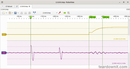
The startup process consists of three phases: 1. Input capacitors charging upon connection to the grid, with a peak amplitude of about 2.6 A, consisting of two portions of one period each. 2. Waiting for the control circuit to start, about 241 ms. 3. (Output Voltage Rise Time) Converter startup, output voltage rise, and transition to operational mode, 56 ms. (Turn On Delay Time) The total time to reach operational mode from power-on is 297 ms.
(Output Voltage Overshoot) The startup process is aperiodic with no overshoot.
Shutdown Characteristics
The shutdown process was tested at 100% load with nominal input voltage at the moment of shutdown. The shutdown waveform is shown below:

The shutdown process can be divided into two phases: 1. (Shut Down Hold Up Time) The unit continues operating, powered by the charge stored in the input capacitors, until their voltage drops to a critical level at which maintaining the output voltage is no longer possible. This phase lasts for 26 ms. 2. (Output Voltage Fall Time) Output voltage decline, converter stop, and acceleration of the voltage drop. This phase lasts for 25 ms.
(Output Voltage Undershoot) The shutdown process is aperiodic, with no undershoot.
Current amplitude at 100% load prior to shutdown was 2.8 A.
Output voltage ripple
At 100% load:
low-frequency ripple of about 10-12 mVp-p at twice the grid frequency, and around 4 kHz with a ripple of 13-15 mVp-p.

At the converter frequency, ripple is approximately 25 mVp-p, with noise at 120 mVp-p.

At 75% load:
low-frequency ripple of about 10 mVp-p at twice the grid frequency and around 12 mVp-p at approximately 4 kHz.

Converter frequency ripple is about 20 mVp-p, with noise at 100 mVp-p.

At 50% load:
low-frequency ripple of about 10 mVp-p at twice the grid frequency and around 15 mVp-p at approximately 4 kHz.

Converter frequency ripple is about 20 mVp-p, with noise at 100 mVp-p.

At 10% load:
low-frequency ripple of about 3-5 mVp-p.

Converter frequency ripple is about 20 mVp-p, with noise at 100 mVp-p.

At 0% load:
The input current was measured with a multimeter at 60 mA. (Power Consumption) Input current in this mode is primarily reactive in nature; thus, the power consumption value measured with handy instruments can't be correct. The input filter has two capacitors, according to the diagram.
At 0% load, low-frequency ripple is hardly distinguishable from the noise, about 3 mVp-p.

Converter frequency ripple is masked by noise around 100 mVp-p.

Dynamic characteristics
Dynamic characteristics were assessed in a mode that switches between 50% and 100% load. The oscillogram below illustrates the process:

It is evident that the unit's response to step-load changes is aperiodic, with the magnitude of the response to load changes being approximately 100 mV p-p.
Overload protection
The manufacturer specifies overload protection with a constant current limiting type, which was confirmed during testing. When overloaded or the output terminals are shorted, the unit enters current limiting mode and automatically recovers after the fault is removed.
The output current at which the limit is triggered is 22 A.
Input safety assessment
(Input Discharge) The input circuit discharge time constant was measured upon disconnection from the grid, with a value of 0.245 s. This means that when operating on a 120V grid, the time required for the input circuits to discharge to safe levels (<42 V) is 0.39 s:

Important: This result applies only to the tested unit and was obtained exclusively for research purposes. It cannot, under any circumstances, be considered a guarantee of safety.

The ground leakage current was measured at 73µA.
Thermal behavior
No significant heating of components was observed during no-load operation. Thermograms were taken at three power levels—80%, 90%, and 100%—with and without the top cover. The thermograms show that the most thermally loaded components of the unit are the NTC inrush current limiters (4), which stand out from the other components. At 80% load, the NTC temperature is 175.6°F (80°C, with a 53°C rise above ambient temperature); at 90% load, it reaches 192.1°F (89°C, with a 62°C rise); and at 100% load, it reaches 203.9°F (95.5°C, with a 68.5°C rise).
The second hottest component, after the NTC, is a resistor, 25 degrees cooler.
80% load


90% load


100% load


Conclusions
The ERPF-400-24 generally exhibits low noise and ripple, and it maintains good accuracy in sustaining the output voltage. The unit has decent dynamic characteristics, responding to pulsating loads without overshoot.
On the startup waveform (see oscillograms), there is an N-shaped section where, after the initial rise in output voltage, a partial drop occurs, followed by another rise and stabilization at the nominal level. This behavior could potentially cause issues when powering up digital devices that require initialization.
The build quality is good. However, the compound is applied somewhat poorly, with notable imperfections and several gaps. Unfortunately, these gaps affect components with increased hygroscopicity, particularly the wire-wound inductances of the output and input noise filters. Despite the manufacturer's claim of “protecting the internal electronic components from rain splash and dust,” this unit should not be used without additional water ingress protection.
According to the specifications, the unit is designed for operation under conditions of "Cooling by free air convection" and "-22F ~ +140°C (Refer to output load derating curve)." The tested unit indeed remains safe up to 100% load during continuous operation. The presence of a temperature sensor on the rectifier diodes adds extra assurance of safety.
Important: The results and conclusions presented apply only to the tested unit and were obtained solely for research purposes. Under no circumstances should they be used to assess all devices of this type.
0 notes