#Bridge Rectifier Diode
Explore tagged Tumblr posts
Visit Tumblr Blog
Explore Tumblr blogs with no restrictions, modern design and the best experience.
Last Seen Tumblr Blogs


Fun Fact
Tumblr Inc. has $15.1M in annual revenue.
Text
VUO160-16NO7: High-Performance Bridge Rectifier Diode by IXYS Corporation
Visit https://www.uscomponent.com/buy/IXYS/VUO160-16NO7 today to explore the VUO160-16NO7 bridge rectifier and other high-quality IXYS Corporation components for your projects.
The VUO160-16NO7 is a bridge rectifier diode designed by IXYS Corporation, a renowned name in the field of high-performance electronic components. As an official IXYS distributor, uscomponent.com proudly offers this diode, ideal for applications requiring reliable rectification and high-power handling.
Key Features of VUO160-16NO7
High Current and Voltage Ratings:
Maximum forward current: 16 amps
Maximum reverse voltage: 1600 volts
High Efficiency and Surge Capability:
Low forward voltage drop for efficient power conversion.
High surge current capacity for demanding applications like power supplies, motor drives, and industrial equipment.
Durable Design:
Compact through-hole package (standard 4-pin configuration) for easy PCB integration.
High-temperature operating range ensures performance in harsh environments.
Built-in Protection:
Features over-voltage and over-current safeguards for safe and reliable operation.
Applications
The VUO160-16NO7 rectifier bridge is engineered for high-power applications such as:
Motor drives
Industrial equipment
Power supplies
Other high-performance electronic systems
Why Choose IXYS Corporation Components?
IXYS is a leader in advanced power modules, semiconductors, and rectification solutions. uscomponent.com, as an official distributor, ensures authentic products and expert support for all your power electronics needs.
#Electronic Components#Electronic Parts Store Near Me#Electronic Parts#Bridge Rectifier#Full Bridge Rectifier#Electronic Components Distributor#Bridge Rectifier Diode#IXYS#Electronic Components Online#Bridge Rectifier For Sale#IXYS Bridge Rectifier#VUO160-16NO7#IXYS Authorized Distributors#IXYS Distributor
0 notes
Text
Schottky Diodes recovery, Schottky bridge rectifier, power management circuits
PMEG4030 Series 40 V 3 A Low VF MEGA Schottky Barrier Rectifier - SOD-123W
0 notes
Text
https://www.futureelectronics.com/p/semiconductors--discretes--diodes--standard-rectifiers/1n4148wtq-7-diodes-incorporated-4041450
Diodes, Standard Rectifiers, 1N4148WTQ-7, Diodes Incorporated
1N4148WT Series 2 A 80 V 150 mW Surface Mount Fast Switching Diode - SOD-523
#Diodes#Standard Rectifiers#1N4148WTQ-7#Diodes Incorporated#what is a rectifier#AC to DC Converters#chip#circuit#Standard Recovery Power Rectifier#bridge rectifier#Half Wave Controlled Rectifier#Diode rectifier circuits
1 note
·
View note
Text
Buy Diodes Bridge Rectifiers with Higher Discount at SUV System Ltd

SUV System Ltd. is slashing prices on a range of high-quality semiconductor devices
With branches across the globe in France, the United Kingdom, Italy, Japan, Israel, China-Taiwan, and beyond, SUV System Ltd is your go-to partner for electronics components like IC (Integrated Circuits), Transistors, Diodes, Capacitors, Resistors, Connectors, Sensors, Inductors, and crystal oscillators. Plus, with logistics warehouses in Hong Kong and Shenzhen, we ensure swift delivery and exceptional service every step of the way. To purchase products click https://www.suvsystem.com/en/plDK299/Diodes%20-%20Bridge%20Rectifiers.html
Don't wait any longer to secure this amazing deal, Contact us at [email protected]
Skype: [email protected]
0 notes
Text
https://www.futureelectronics.com/p/semiconductors--discretes--diodes--scottky-rectifiers/pds5100-13-diodes-incorporated-6129425
What is Diode, high frequency, high Voltage Schottky Barrier Rectifier
PDS5100H Series 100 V 5 A High Voltage Schottky Barrier Rectifier - PowerDI-5
#Diodes Incorporated#PDS5100-13#Diodes#Schottky Rectifiers#High speed rectifier diodes#Microwave diode#RF Diode#high frequency#high Voltage Schottky Barrier Rectifier#circuit#Recovery diode#Schottky bridge rectifier#rectifier chip
1 note
·
View note
Text
https://www.futureelectronics.com/p/semiconductors--discretes--diodes--scottky-rectifiers/pds5100h-13-diodes-incorporated-9401746
High Voltage Schottky Barrier Rectifier, Fast rectifier diode, power diode
PDS5100H Series 100 V 5 A High Voltage Schottky Barrier Rectifier - PowerDI-5
#Diodes Incorporated#PDS5100H-13#Diodes#Schottky Rectifiers#Power management circuits#ultra high-speed#bridge rectifier#High Voltage Schottky Barrier Rectifier#Fast rectifier diode#power diode#Rectifier power circuits#Microwave diode#RF
1 note
·
View note
Text
https://www.futureelectronics.com/p/semiconductors--discretes--diodes--schottky-diodes/bat54sw-13-f-diodes-incorporated-1129353
Diodes, Schottky Diodes, BAT54SW-13-F, Diodes Incorporated
BAT54W Series 30 V 0.2 A Surface Mount Schottky Barrier Diode - SOT323
#Diodes#Schottky Diodes#BAT54SW-13-F#Diodes Incorporated#power supplies#Switching Diodes#TV tuners#high frequency#power circuits#schottky bridge rectifier#power management circuits#Recovery diode
1 note
·
View note
Text
RF Diodes, Surface Mount Schottky Power Rectifier, high frequency,
PDS5100 Series 100 V 5 A High Voltage Schottky Barrier Rectifier - PowerDI-5
#Diodes#Schottky Rectifiers#PDS5100-13#Diodes Incorporated#schottky bridge rectifier#MEGA Schottky Barrier Rectifier#what is a Schottky#power circuits#Power management circuits#RF Diodes#Surface Mount Schottky Power Rectifier#high frequency
1 note
·
View note
Text
Semikron SKD160-16 Bridge Rectifier Diode: High-Power Solution for Industrial Applications
For more information or to purchase the SKD160-16, visit the official website of Semikron distributor https://www.uscomponent.com/buy/Semikron/SKD160-16.
With its combination of high surge current capability, rugged design, and high efficiency, the Semikron SKD160-16 Bridge Rectifier Diode offers reliable performance in even the most demanding industrial environments. Its compact yet durable package ensures it can withstand harsh conditions while delivering consistent and efficient power conversion.
By choosing the Semikron SKD160-16, you benefit from a trusted solution for high-power applications that demand efficiency, reliability, and durability.
SKD160-16 is a high-power Bridge Rectifier Diode produced by Semikron, a leading manufacturer of power electronics components. It is designed for use in high-current applications and is widely used in power supplies and industrial automation systems.
The SKD160-16 Bridge Rectifier Diode is a four-terminal device consisting of four diodes that are arranged in a bridge configuration. This configuration allows for the conversion of an alternating current (AC) input signal to a direct current (DC) output signal.
The diode has a maximum current rating of 160A and a maximum voltage rating of 1600V, making it suitable for high-power applications. It is also designed with a high surge current capability, which enables it to handle brief overloads without damage.
The SKD160-16 Bridge Rectifier Diode is designed with low forward voltage drop and low reverse recovery time, which results in low power dissipation and high efficiency. It is also designed with a rugged and reliable package, which provides excellent thermal performance and high resistance to mechanical stress.
Overall, the SKD160-16 Bridge Rectifier Diode is a high-performance device that provides efficient and reliable power conversion capabilities in high-power applications. Its rugged design and high surge current capability make it suitable for use in harsh environments and industrial applications that require high reliability and durability.
#Diode#Bridge Rectifier#Transistor#Full Wave Bridge Rectifier#Bridge Rectifier Diode#High Current Bridge Rectifier#High Power Bridge Rectifier#Module Transistor#Transistor Module#SKD160-16#Semikron SKD160-16#Semikron Authorized Distributors#Semikron Distributor
0 notes
Note
tell me everything about AC to DC filters Right Now
:0
Dear god.
OK I have to make some assumptions or else this is going to get really long. I am going to assume that you already know what AC and DC are. I am going to assume that you took (and passed) geometry, so a sine wave and it's variations are familiar to you. I am also going to assume that you also know the difference between voltage, current, and resistance.
So, what are AC to DC, why do we care about that? Well, the electricity coming out of the wall is AC, but in order to, lets say, charge your laptop battery, you need DC. In fact, if you look at a laptop charger, you'll see The Brick. The thick rectangle that gets hot when charging the laptop.
THAT'S THE AC TO DC CONVERTER
I just called it converter instead of filter. Why? Because filters technically only remove a 'ripple' from DC current, so a current that's almost DC but not quite. If you are making the entire jump from AC to DC, then that's called a converter.
Now here's where things get fucked.

These are all of the parts after the plug. The load is your laptop, the regulator is your filter.
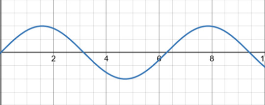
Let's say that this is your AC signal (this graph showing the voltage over time). Now, the first thing this passes through is the transformer, which only adjusts the voltage to the correct level. Some devices need it higher, some lower. Let's say that this transformer is a step up transformer, because it made the signal bigger.

The next step is the rectifier. Now, traditionally this part is taught in stages in order to show it's affect on the signal. I'm going to speed run that. I will assume that you're familiar with what a diode is. If you aren't, just know that it only allows current to flow in one direction. So, anything going backwards will be removed. Picture a one way valve.
So, if we were to send this signal through one diode, then that would leave us with
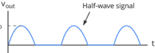
just the positive half! That's why this setup is called a Half-wave rectifier.
But what if we were to use two diodes. As in, fill in the blank spot that the negative half left with another positive bump. That would give us

This lovely thing! Which is great, but it requires another AC signal that is 180 degrees off from the original one in order to exist. Which, transformers exist which can provide that, but it's not cost effective. So, that leaves us with the most common setup, the Bridge Rectifier.
I've been skipping the circuit diagram so far, but now it's important.
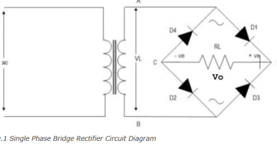
THIS thing is a bridge rectifier connected to the transformer (yes that's what transformers look like according to circuit diagram shorthand). Now, I am American, and for some reason American electricians use that up and down sharp thing in the middle of the diamond to indicate a resistor. Europe uses a rectangle. Again, I am going to assume that you know what a resistor does.
Those four black triangles with lines? Those are diodes. The line across the tip of the triangle indicates what direction they are allowing current to flow into. Now picture you were a positive signal flowing in through point A into the bridge. There's a split in the circuit, but one way (diode D4) is blocked, so you have to go across diode D1. Now you're at the edge of the diamond, once again two ways you can go. You head towards diode D2, because diode D3 won't let you through. What that looks like is this
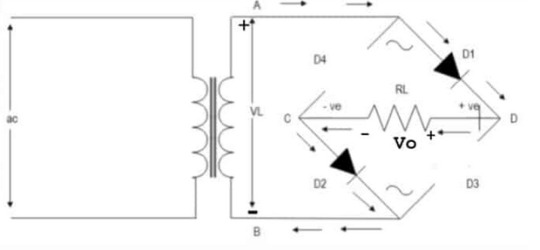
What about the other direction? Well that looks like
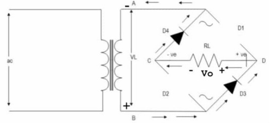
Notice that the edges of the diamond are called out? Points C and D. That's the money makers. You see, if you plug into point D as your positive and C as your negative, you get a full wave signal! (so sorry for not going fully in depth on why that works just trust me it's a bit of a mess and should really be taught with the actual circuit in front of you, not across the internet like this)
A full wave signal is completely positive, but it's not exactly DC yet. That's where smoothing comes in. This is done with a capacitor!

The capacitor is charged up and then slowly releases it's charge. But before it can completely discharge, it gets recharged by the next wave. Quick review, a capacitor is like a battery where it can be charged up, but unlike a battery which holds charge with chemistry, capacitors hold charge with physics. They can still wear out, but not nearly as quickly as a battery.
What does that red line look like? Well, almost like a straight line, except it has RIPPLES! That's right, we're finally back to the filter! Or the regulator as the diagram calls it. Means the same thing.
Sometimes, this step is skipped. If the device getting signal isn't too sensitive or it's just cheep, then the electricity stays bouncy. Some devices really care about any fluxuation in the signal, in which case they get a big expensive filter.
Unfortunately, the inner bits of a filter are many, so I won't be going into all of that. But you want me to go into that, so I will show a circuit diagram.
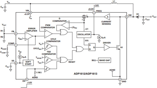
This is a diagram of the ADP1612
This website has a downloadable version of the spec sheet!
But that's a level of detail that you usually only get into if you are planning on building a circuit. The day that you're flipping through spec sheets in order to check compatibility is when you've really become an engineer.
So that's how you go from AC into DC. Yes, I just spent an hour typing this all out. I like electricity a lot.
Here's a GREAT video that goes over all of this but the guy actually has a circuit and an ossiliscope in front of him to show the signal.
#electricity#electronic#electrical engineers#physics#AC to DC rectifier#electrical engineering#mmm electricity for power#ask#literally several college classes worth of info that I am skipping in this#ough my circuit bits#I chose the perfect degree I am built for this shit
11 notes
·
View notes
Text
Orange Bass Terror 1000
This amp really gave me a hard time. This amp belongs to the bass player for my band. The original issue was that the signal would cut out in the middle of practice or shows and the head would just fizzle out and shut down.

My initial thoughts were that the class D power amp was failing due to overheating. On the bench, heat seemed fine, fan kicked on with no issues and parts weren’t getting too hot, but voltages were not normal in the power supply. These amps have a smps mounted on the top of the amp.


I spent some time replacing dodgy electrolytic caps in the switching part of the power supply. Didn’t help. I flipped the amp over, voltages seemed okay for the most part but at the first power amp mosfet, there was a short between all three legs. I replaced that mosfet and the amp started to blowing fuses every time I powered it up on the variac and the fan and indicator light weren’t turning on anymore. Tracing that back through the power supply, one of the switching mosfets had failed causing the bridge rectifier, and power switching IC to fail as well. I replaced the mosfets, the IC, and the bridge rectifier.
Now we had decent voltages to most of the amp except for the -53V rail which was way off.
I started testing diodes and found that D5 in the power amp was shorted.


Of course that diode is totally inaccessible without removing the huge inductor. Once the inductor was out, the diode wasn’t reading short anymore. I was able to trace this back and the only thing that made sense was another failing power amp mosfet.

I went through and replaced the rest of the power amp mosfets and we were rocking.
Special thanks to my Rigol DS1052E on this one. Couldn’t have done it without you.
-Kaden
2 notes
·
View notes
Text
I didn’t think I’d need to say this, but apparently I do:
Don’t use the Raspberry Pi 2040 to build a DCC decoder.
It’s not really wrong, of course, and it gives you ridiculous amounts of computing power, but to get that you need miles and miles of extra components. Like a dozen of decoupling capacitors, an external oscillator, and of course an external flash memory. You can maybe do that sort of thing in H0, but for real model trains, it’s just not ideal. Pick something like an ATTiny or STM32C0 (I’ve done both for different projects): Cheap, just one or two decoupling capacitors, no external oscillator required and no external flash memory needed either.
The versions of the RP2350 with built in memory may be a better idea, once they fix the GPIO issues anyway, but still, there’s the oscillator and just way too many capacitors.
(Some of these concerns may be different if you want to add sound support, which requires more memory anyway. But I’d argue that sound in model railroads is a mistake anyway. I’ve never seen an N scale locomotive that sounds good, it’s all just an annoying expensive gimmick.)
Also while we’re at it, don’t use a cheap standard bridge rectifier. The steep slopes of the DCC signal mandate a really fast rectifier, typically Schottky diodes. This is particularly important when you have RailCom on your layout. You may need four individual diodes instead of one rectifier, but since you won’t need all the capacitors of the RP2040, you still win out in the end (it’s also typically smaller than the rather large SMD standard rectifiers).
This is a call-out post for https://github.com/gab-k/RP2040-Decoder . It’s a useful project, but it’s also far from ideal.
4 notes
·
View notes
Text
That's a full wave bridge rectifier. It's a (now somewhat outdated in most applications) method of getting a steady DC (or DC-ish) current from an alternating current. The transformer to the left of the diagram (basically two big coils of wire with a specific number of loops relative to each other) gets used to step an AC voltage up or down to a peak voltage a little above the final desired DC voltage. Then the diode circuit on the right has the effect of letting the positive part of the wave through and inverting the negative part of the AC sine wave.
Paired with a capacitor and a voltage regulator, you can get a pretty clean DC voltage out the other side with a well-designed rectifier.
But we tend to use a more modern circuit design now, which doesn't require the big, bulky transformers used in linear power supply circuits like the above. The new ones still need a transformer, but it can be much smaller. That's why phone chargers and other chargers got so much smaller and lighter recently — there's just a lot less copper wire inside.
And not to burst any bubbles, but in practice, rectifier circuits aren't physically laid out like the diagrams. Here's one, with the capacitor, but without the transformer component. That would get hooked up to two of the screw terminals, and the other two are the DC output.

i unironically believe electricity is the closest thing we have to magic in this universe. consider:
it's basically what human "souls" are made of (your consciousness is the result of miniscule amounts of electric charge jumping between neurons in your brain)
when handled incorrectly or encountered in the wild, it is a deadly force that can kill you in at least half a dozen different ways
when treated respectfully and channeled into the proper conduits, it is a power source that forms the backbone of modern society
if you engrave the right sigils into a rock and channel electricity into it, you can make the rock think
there is a dedicated caste of mages (electrical engineers) tasked with researching it in ivory towers
whatever the fuck Galvani was doing with those frog legs
look at this and just try to tell me it isn't a kind of summoning circle

52K notes
·
View notes
Text
MB1S Diodes - Bridge Rectifiers at higher discount only by SUV System Ltd

SUV System Ltd, your go-to electronic component supplier, is rolling out SPECIAL DISCOUNTS on their hottest selling #semiconductordevices
With offices in Hong Kong and Shenzhen, and a fully stocked product warehouse, we offer a wide range of products from leading brands. We guarantee the authenticity and quality of every component we supply. With strict standards and certifications including ESD, ISO9001, ISO14001, ISO45001, and ISO13485, you can trust that you're getting the best of the best.
Don't wait any longer to secure this amazing deal, Contact us at [email protected]
Skype: [email protected]
To purchase this product, click https://www.suvsystem.com/en/plDK299pi/MB1S.html
0 notes
Text
Clean, Reliable Output – Choose a Trusted Three-Phase Diode Bridge Rectifier!
Looking for clean, stable, and reliable DC power in demanding environments? A three-phase diode bridge rectifier is your go-to solution. From motor drives to renewables, it ensures efficient AC to DC conversion with low ripple and high durability. Power smart. Power steady.
0 notes
Text
Closing in on superconducting semiconductors
New Post has been published on https://sunalei.org/news/closing-in-on-superconducting-semiconductors/
Closing in on superconducting semiconductors

In 2023, about 4.4 percent (176 terawatt-hours) of total energy consumption in the United States was by data centers that are essential for processing large quantities of information. Of that 176 TWh, approximately 100 TWh (57 percent) was used by CPU and GPU equipment. Energy requirements have escalated substantially in the past decade and will only continue to grow, making the development of energy-efficient computing crucial.
Superconducting electronics have arisen as a promising alternative for classical and quantum computing, although their full exploitation for high-end computing requires a dramatic reduction in the amount of wiring linking ambient temperature electronics and low-temperature superconducting circuits. To make systems that are both larger and more streamlined, replacing commonplace components such as semiconductors with superconducting versions could be of immense value. It’s a challenge that has captivated MIT Plasma Science and Fusion Center senior research scientist Jagadeesh Moodera and his colleagues, who described a significant breakthrough in a recent Nature Electronics paper, “Efficient superconducting diodes and rectifiers for quantum circuitry.”
Moodera was working on a stubborn problem. One of the critical long-standing requirements is the need for the efficient conversion of AC currents into DC currents on a chip while operating at the extremely cold cryogenic temperatures required for superconductors to work efficiently. For example, in superconducting “energy-efficient rapid single flux quantum” (ERSFQ) circuits, the AC-to-DC issue is limiting ERSFQ scalability and preventing their use in larger circuits with higher complexities. To respond to this need, Moodera and his team created superconducting diode (SD)-based superconducting rectifiers — devices that can convert AC to DC on the same chip. These rectifiers would allow for the efficient delivery of the DC current necessary to operate superconducting classical and quantum processors.
Quantum computer circuits can only operate at temperatures close to 0 kelvins (absolute zero), and the way power is supplied must be carefully controlled to limit the effects of interference introduced by too much heat or electromagnetic noise. Most unwanted noise and heat come from the wires connecting cold quantum chips to room-temperature electronics. Instead, using superconducting rectifiers to convert AC currents into DC within a cryogenic environment reduces the number of wires, cutting down on heat and noise and enabling larger, more stable quantum systems.
In a 2023 experiment, Moodera and his co-authors developed SDs that are made of very thin layers of superconducting material that display nonreciprocal (or unidirectional) flow of current and could be the superconducting counterpart to standard semiconductors. Even though SDs have garnered significant attention, especially since 2020, up until this point the research has focused only on individual SDs for proof of concept. The group’s 2023 paper outlined how they created and refined a method by which SDs could be scaled for broader application.
Now, by building a diode bridge circuit, they demonstrated the successful integration of four SDs and realized AC-to-DC rectification at cryogenic temperatures.
The new approach described in their recent Nature Electronics paper will significantly cut down on the thermal and electromagnetic noise traveling from ambient into cryogenic circuitry, enabling cleaner operation. The SDs could also potentially serve as isolators/circulators, assisting in insulating qubit signals from external influence. The successful assimilation of multiple SDs into the first integrated SD circuit represents a key step toward making superconducting computing a commercial reality.
“Our work opens the door to the arrival of highly energy-efficient, practical superconductivity-based supercomputers in the next few years,” says Moodera. “Moreover, we expect our research to enhance the qubit stability while boosting the quantum computing program, bringing its realization closer.” Given the multiple beneficial roles these components could play, Moodera and his team are already working toward the integration of such devices into actual superconducting logic circuits, including in dark matter detection circuits that are essential to the operation of experiments at CERN and LUX-ZEPLIN in at the Berkeley National Lab.
This work was partially funded by MIT Lincoln Laboratory’s Advanced Concepts Committee, the U.S. National Science Foundation, U.S. Army Research Office, and U.S. Air Force Office of Scientific Research.
0 notes