#module lora arduino
Explore tagged Tumblr posts
Visit Tumblr Blog
Explore Tumblr blogs with no restrictions, modern design and the best experience.
Last Seen Tumblr Blogs


Fun Fact
In 2020, Tumblr had 29.4 million users in the US.
Text
Transferência de Arquivos via LoRa
Um projeto que venho fazendo há alguns meses e que muitas pessoas estavam interessadas em transmitir imagens e agora será possível, mas claro, respeitando as limitações.
Transferência da arquivos via LoRa é possível assim como qualquer outra modulação, mas existem desafios particulares nessa tarefa que em outras modulações podem ser mais fáceis. Sobre a modulação LoRa Antes mesmo de partimos para a transferência de arquivos via LoRa, é preciso entender que o LoRa não foi feito para esse tipo de aplicação e sim para dispositivos IoT, mesmo embora tenha uma taxa…

View On WordPress
#arduino lora antenna#biblioteca lora arduino#esp32 lora arduino#esp32 lora arduino library#lora and arduino#lora arduino#lora arduino adafruit#lora arduino board#lora arduino example#lora arduino library#lora arduino projects#lora transmitter and receiver arduino#module lora arduino#multiple lora arduino#rfm9x lora arduino
0 notes
Text
Best Electronic Components Suppliers in Delhi - Campus Component
In the ever-evolving world of electronics, finding a reliable and trustworthy source for high-quality electronic components is essential. Campus Component, a leading electronic components distributor in India, stands out as a premier destination for a wide range of components catering to diverse industry needs. With a commitment to excellence, Campus Component has established itself as the go-to partner for engineers, hobbyists, and businesses seeking top-notch electronic components and exceptional customer service.
A Comprehensive Range of Electronic Components
Campus Component boasts an extensive inventory of electronic components, encompassing a vast spectrum of categories, including:
Microcontrollers and Development Boards: Discover a comprehensive selection of microcontrollers and development boards from renowned brands like Arduino, ESPRESSIF, and NUVOTON, empowering you to bring your electronic creations to life.
Sensors: Enhance your projects with a diverse range of sensors, including temperature sensors, proximity sensors, and accelerometers, enabling you to interact with the physical world with precision and accuracy.
Relays: Control and regulate electrical circuits with a broad assortment of relays, including power relays, PCB relays, and solid-state relays, ensuring reliable and efficient power management.
Wireless Modules: Expand the connectivity of your projects with a wide array of wireless modules, including Bluetooth modules, Wi-Fi modules, and LoRa modules, enabling seamless communication and data exchange.
Campus Component: Your Trusted Source for Electronic Components
In a landscape brimming with electronic components distributors, Campus Component distinguishes itself with its unwavering commitment to quality, customer-centric approach, and dedication to innovation. Whether you're seeking a single resistor or a comprehensive suite of components for your next project, Campus Component stands as a reliable partner, ensuring you have access to the high-quality electronic components you need to bring your ideas to life.
Embrace the Power of Electronics with Campus Component
Join Campus Component's growing community of engineers, hobbyists, and businesses and discover the power of high-quality electronic components. With an extensive inventory, unwavering commitment to quality, and customer-centric approach, Campus Component is your one-stop shop for all your electronic components needs.
#buy electronic components online india#buy electronic components in bulk#electronic components online in india
0 notes
Text
How do you handle water meter reading using Lora (Raspberry Pi, Arduino, Lorawan, IoT)?
Install a LoRaWAN Gateway: Begin by setting up a LoRaWAN gateway. This gateway acts as a receiver for data transmitted by LoRaWAN devices and forwards it to the network server. It connects to the internet and communicates with LoRaWAN devices within its coverage area.
Attach LoRaWAN Modules to Water Meters: Next, equip your water meters with LoRaWAN modules or sensors. These modules are responsible for gathering important data, such as water consumption readings, from the meters.
Develop Firmware/Software: Program your Raspberry Pi or Arduino device to collect data from the water meters through the LoRaWAN modules. This programming may involve utilizing the LoRaWAN library or SDK provided by the module manufacturer.
Set Up a LoRaWAN Network Server: Install and configure a LoRaWAN network server. This server will receive and handle data from the water meters. Its functions include managing device registrations, routing messages, and storing data.
Ensure Secure Data Transmission and Encryption: Utilize LoRaWAN protocols to securely transmit the water meter readings from your Raspberry Pi or Arduino to the network server. LoRaWAN uses AES encryption to safeguard data privacy during transmission.
Data Processing and Storage: Once the network server receives the data, process it as needed. Extract the relevant water consumption readings and conduct any necessary calculations or validations. Store the data in a database or another suitable storage system.
Integration and Visualization: To make sense of the data, integrate it with your chosen IoT platform or application. This integration allows for further analysis and visualization. Consider creating a web-based dashboard or a mobile app to present the water consumption data in a user-friendly and informative manner.
It's important to keep in mind that the specific steps and details of implementation may vary based on the hardware and software components you select and any unique requirements associated with your water meter system. Adapt the above steps as necessary to align with your specific setup and development environment.
0 notes
Video
youtube
How can we use Arduino to make creative projects?
Innovation & Implementation - S1E8
Arduino is an open-source platform used for building electronics projects. Arduino consists of both a physical programmable circuit board and a piece of software, or IDE (Integrated Development Environment) that runs on your computer, used to write and upload computer code to the physical board. The Arduino platform has become quite popular with people just starting with electronics.
Today we’ll introduce plenty of amazing Arduino projects. Let’s go check them together! And we have prepared Arduino Module gifts for our lovely audiences! Leave your comment to win Gifts!
-
Subscribe our Youtube channel: https://www.youtube.com/watch?v=mftIgeS_GGU&t=567s
-
#arduino#project#pcbdesign#open source#electronics#programming#software#IDE#shared project#module#youtube#pcbway#DIY#maker#LORA#raspberry pi
9 notes
·
View notes
Text
Long-Range IoT Communication with LoRa Modules: SX1278 and ESP32 with Display
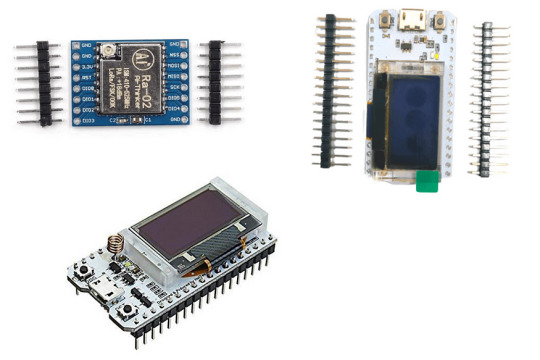
SX1278 LoRa Module
The SX1278 LoRa module is a popular choice among developers due to its low power consumption, long-range capabilities, and support for multiple frequency bands. It is based on the Semtech SX1278 chip, which is a low-power, long-range transceiver designed for use in the Industrial, Scientific, and Medical (ISM) frequency bands. The module operates in the 433MHz frequency band and has a range of up to 5 km in open space.
The SX1278 LoRa module can be easily integrated into a variety of applications, including Internet of Things (IoT) devices, smart cities, and remote monitoring systems. It supports a wide range of data rates, from 300 bps to 37.5 kbps, and has a programmable output power up to +20 dBm.
One of the key advantages of the SX1278 LoRa module is its low power consumption. It has a sleep mode that consumes only 0.1 µA of current, making it an ideal choice for battery-powered applications. The module also has a built-in temperature sensor and a low battery detector, which can be used to optimize power consumption and extend battery life.
ESP32 LoRa with Display SX1278
The ESP32 LoRa with Display SX1278 is a popular implementation of the SX1278 LoRa module. It combines the low power consumption and long-range capabilities of the SX1278 with the processing power and connectivity features of the ESP32 microcontroller. The module has a 128x64 OLED display, which can be used to display sensor readings, status messages, and other information.
The ESP32 LoRa with Display SX1278 is compatible with the Arduino IDE and can be programmed using the Arduino programming language. It has a built-in WiFi and Bluetooth connectivity, which allows it to connect to other devices and the Internet. The module also has a built-in antenna, which simplifies the integration process and reduces the overall size of the device.
One of the key features of the ESP32 LoRa with Display SX1278 is its ease of use. It comes with a preloaded firmware that can be easily customized using the Arduino IDE. The firmware includes support for LoRaWAN, a popular protocol for building large-scale IoT networks. The module can also be used with other LoRa protocols, such as LoRa-MAC, LoRa-RAW, and LoRa-P2P.
ESP32 LoRa with Display SX1276
The ESP32 LoRa with Display SX1276 is another popular implementation of the ESP32 LoRa module, but this time with the SX1276 chip. The module operates in the 868 MHz frequency band and has a range of up to 10 km in open space. Like the SX1278 module, it has a low power consumption and can be used in a variety of applications, including smart agriculture, environmental monitoring, and asset tracking.
The ESP32 LoRa with Display SX1276 has a 128x64 OLED display, which can be used to display sensor readings and other information. It also has a built-in antenna and a WiFi/Bluetooth connectivity, which allows it to connect to other devices and the Internet.
One of the key advantages of the ESP32 LoRa with Display SX1276 is its compatibility with the Arduino IDE. It can be programmed using the Arduino programming language and comes with a preloaded firmware that can be easily customized. The firmware includes support for LoRaWAN and other LoRa protocols, making it easy to build large-scale IoT networks.
In addition to its low power consumption and long-range capabilities, the ESP32 LoRa with Display SX1276 has a variety of features that make it an ideal choice for IoT applications. It has a built-in accelerometer and gyroscope, which can be used for motion sensing and orientation detection. It also has a built-in GPS module, which can be used for location tracking and geofencing.
The module can be powered by a variety of sources, including batteries, solar panels, and external power sources. It also has a deep sleep mode that consumes only 10 µA of current, making it an ideal choice for battery-powered applications.
Conclusion
The SX1278 LoRa module and the ESP32 LoRa with Display modules are two popular choices for developers looking to build IoT applications that require long-range communication and low power consumption. The SX1278 module is a versatile solution that can be easily integrated into a variety of applications, while the ESP32 LoRa with Display modules provide additional features, such as processing power, connectivity, and display capabilities.
When selecting a LoRa module, developers should consider their specific requirements, such as range, power consumption, data rate, and frequency band. They should also consider the features and capabilities of the module, such as built-in sensors, connectivity options, and compatibility with different protocols and programming languages.
Overall, LoRa technology provides an attractive alternative to traditional wireless communication technologies, such as WiFi and Bluetooth, for IoT applications that require long-range communication and low power consumption. With the availability of versatile LoRa modules, such as the SX1278 LoRa module and the ESP32 LoRa with Display modules, developers have more options than ever before to build innovative IoT solutions.
0 notes
Text
[Media] TTGO T-Beam ESP32 LoRa
TTGO T-Beam ESP32 LoRa The TTGO T-Beam is a long-range wireless capable board supporting LoRa, built around a dual-core ESP32 chip with 4MB of SPI flash onboard, providing both Wi-Fi and Bluetooth LE. The board's LoRa support comes in three different variants, operating at 433MHz, 868MHz, and 915MHz depending on region, with an included SMA antenna. Location tracking is provided by the onboard u-blox NEO-6M GPS module with ceramic antenna, and the board offers 26-pin headers with GPIO, ADC, VP/VN, DAC, touch, SPI, I2C, UART, 2דLoRa” pin, and power signals (5V/3.3V/GND). The board can be programmed using the Arduino development environment, and example code shows you how to both send and receive data via LoRa. The board also includes a battery holder for a 18650 Li-Ion cell. Repository: https://github.com/Xinyuan-LilyGO/LilyGo-LoRa-Series Buy online: 🛒 https://alii.pub/6mgzin 🛒 https://amzn.to/3Z2WUh4 #radio #lora #mesh #ESP32

0 notes
Text
JSON-Format zur Datenübertragung zwischen zwei Mikrocontroller
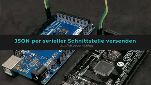
In diesem Beitrag möchte ich dir zeigen, wie du das JSON-Format zur Datenübertragung zwischen zwei Mikrocontroller verwenden kannst.

Die Idee zu diesem Beitrag kam aus den Kommentaren zum Beitrag Übertragen von Sensordaten per nRF24L01 Modul wo ich Sensordaten mit diesem Format von einem Arduino zum anderen sende. In dem verlinkten Beitrag habe ich die JSON-Daten per Hand geparst, hier möchte ich nun einen bequemen Weg zeigen, wie dieses mit einer Bibliothek geht.
Warum das JSON-Format?
Der Vorteil am JSON-Format ist, dass dieses einfach zu lesen und auch zu erweitern ist. Des Weiteren ist dieses gut komprimiert bzw. lässt sich gut komprimieren und somit ist eine hohe Datenübertragung möglich. { "vorname":"Stefan", "nachname":"Draeger", "alter":42 } Um ein selbst erstelltes JSON-Objekt zu prüfen, bieten sich einige Onlinetools wie Bsp https://jsonformatter.curiousconcept.com/# an. Hier bekommst du bei einem Fehler gleich den Hinweis, was fehlerhaft ist bzw. das Tool ergänzt sogar fehlende Anführungszeichen.
Benötigte Ressourcen für den Aufbau
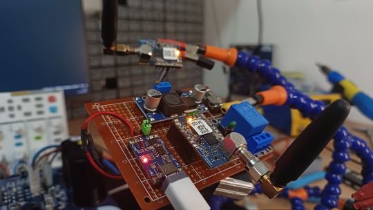
Wenn du dieses kleine Projekt nachbauen möchtest, dann benötigst du: - einen Mikrocontroller Bsp Arduino Mega 2560 R3, - ein USB Datenkabel Der Arduino Mega 2560 R3 hat den Vorteil, dass dieser mehrere hardwareseitige serielle Schnittstellen hat.
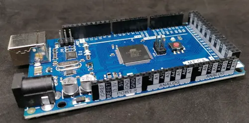
Funduino MEGA 2560 R3 - Buchsenleisten mit Pinbeschriftungen
Arduino UNO / Nano V3
Natürlich kannst du auch einen Arduino UNO oder Nano verwenden, diese haben lediglich nur einen seriellen Anschluss, und dieser ist beim Upload des Sketches belegt, somit musst du die Verbindungen (Breadboardkabel) vor dem Hochladen des Programmes entfernen. Alternativ kannst du auch die Bibliothek SoftwareSerial verwenden und somit zwei digitale Pins des Arduino UNOs als zusätzlichen seriellen Anschluss definieren.
Verbinden von zwei Mikrocontroller per serieller Schnittstelle
https://youtu.be/bEx_ASdbDXQ Die beiden Mikrocontroller kannst du auf verschiedene Wege verbinden, entweder per Bluetooth, nRF24L01, LoRa oder ganz einfach per serieller Schnittstelle. In diesem Beitrag verwende ich die serielle Schnittstelle, da dieses recht einfach ist und vor allem das eigentliche Projekt nicht zusätzlich durch Bibliotheken aufbläht.

zwei Arduino Mega per serieller Schnittstelle verbunden Auf der Grafik ist zu sehen, dass die Kontakte RX & TX jeweils über Kreuz verbunden sind.
Programmieren
Nachdem wir nun die beiden Mikrocontroller verbunden haben, kommen wir zur Programmierung. Wie erwähnt möchte ich eine Bibliothek zum Verarbeiten der JSON Daten verwenden. Bibliothek - Arduino_JSON Bevor wir mit der eigentlichen Programmierung beginnen, installieren wir die benötigte Bibliothek über den Bibliotheksmanager der Arduino IDE. Zunächst öffnen wir den Bibliotheksverwalter in der Arduino IDE (1) danach suchen wir nach "json" (2) und wählen an dem Eintrag "Arduino_JSON by Arduino" die Schaltfläche "INSTALL" (3). Wenn die Installation abgeschlossen ist, dann erscheint der Text "INSTALLED" (4).
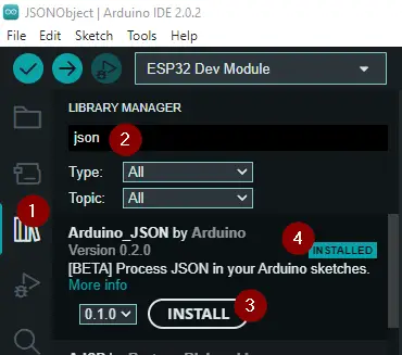
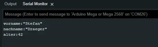
Installieren der Bibliothek Arduino_JSON über den Bibliotheksverwalter Parsen eines JSONs Zerlegen wir zunächst einmal auf einem Mikrocontroller ein kleines JSON. { "vorname":"Stefan", "nachname":"Draeger", "alter":42 } Damit wir dieses JSON in eine String Variable ablegen können, müssen wir alle Anführungszeichen escapen, d.h. wir setzen ein Backslash davor. {"vorname":"Stefan", "nachname":"Draeger", "alter":42} Nachfolgend ein kleines Programm zum Parsen von JSON Daten auf dem Arduino. // einbinden der Bibliothek zum verarbeiten von JSON #include // das JSON-Objekt welches verarbeitet werden soll String input = "{"vorname":"Stefan", "nachname":"Draeger", "alter":42}"; void setup() { // beginn der seriellen Kommunikation mit 9600 baud Serial.begin(9600); // initialisieren eines JSONVar Objektes // mit den verarbeiteten JSON Daten JSONVar jsonVar = JSON.parse(input); // prüfen ob es ein Key mit der Bezeichnung "vorname" gibt. if (jsonVar.hasOwnProperty("vorname")) { // Ausgeben der Zeichenkette "vorname:" auf der seriellen Schnittstelle Serial.print("vorname:"); // Ausgeben des Wertes zum Key Serial.println(jsonVar); } if (jsonVar.hasOwnProperty("nachname")) { Serial.print("nachname:"); Serial.println(jsonVar); } if (jsonVar.hasOwnProperty("alter")) { Serial.print("alter:"); Serial.println(jsonVar); } } void loop() { // bleibt leer } Die Ausgabe auf der seriellen Schnittstelle bzw. im seriellen Monitor sieht wie folgt aus:
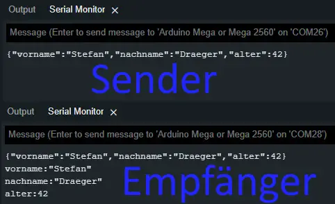
Übertragen eines JSON zwischen zwei Mikrocontroller per serieller Schnittstelle Im nächsten Schritt wollen wir ein JSON zwischen zwei Mikrocontroller übertragen. Das JSON könnte hier Sensordaten (Temperatur, Luftdruck, relative Luftfeuchtigkeit, CO₂ Konzentration etc.) enthalten. In meinem Fall möchte ich das JSON mit festen Daten beschreiben. Quellcode des Senders // einbinden der Bibliotheken zum verarbeiten // von JSON #include JSONVar output; void setup() { // beginn der seriellen Kommunikation mit 9600 baud Serial.begin(9600); Serial1.begin(9600); // einfügen des Schlüssel/Werte Paares in // das JSON-Objekt output = "Stefan"; output = "Draeger"; output = 42; // Umwandeln des JSON-Objektes in ein String String jsonOutput = JSON.stringify(output); Serial.print(jsonOutput); Serial1.print(jsonOutput); } void loop() { // put your main code here, to run repeatedly: } Quellcode des Empfängers Am Empfänger müssen wir "lauschen", ob Daten an der seriellen Schnittstelle anliegen und diese dann mit der Funktion "readString()" im Ganzen lesen. Diese gelesenen Daten parsen wir dann in ein JSON-Objekt und können diese, wie zuvor im einfachen Beispiel gezeigt, auswerten und ausgeben. // einbinden der Bibliotheken zum verarbeiten // von JSON #include void setup() { // beginn der seriellen Kommunikation mit 9600 baud Serial.begin(9600); Serial1.begin(9600); } void loop() { while (Serial1.available() > 0) { String data = Serial1.readString(); Serial.println(data); // initialisieren eines JSONVar Objektes // mit den verarbeiteten JSON Daten JSONVar jsonVar = JSON.parse(data); // prüfen ob es ein Key mit der Bezeichnung "vorname" gibt. if (jsonVar.hasOwnProperty("vorname")) { // Ausgeben der Zeichenkette "vorname:" auf der seriellen Schnittstelle Serial.print("vorname:"); // Ausgeben des Wertes zum Key Serial.println(jsonVar); } if (jsonVar.hasOwnProperty("nachname")) { Serial.print("nachname:"); Serial.println(jsonVar); } if (jsonVar.hasOwnProperty("alter")) { Serial.print("alter:"); Serial.println(jsonVar); } } } Hier nun die Ausgaben auf der seriellen Schnittstelle in der Arduino IDE.
Downloads
Hier der Quellcode zu den Beispielen aus diesem Beitrag zum bequemen Download. Read the full article
0 notes
Text
GPIOs do LoRaMesh da Radioenge: Portas digitais
Aprenda como usar as GPIOs do módulo LoRaMesh da Radioenge
As GPIOs do LoRaMesh da Radioenge possibilita que possamos fazer aplicações de automação com um uso reduzido de hardware, dedicando apenas ao circuito de chaveamento (se necessário) e de alimentação. No total temos no LoRaMesh 8 GPIOs sendo todas configuráveis como entrada ou saída digital e duas como leitura analógica. Porém neste post vamos apenas abordar as portas digitais. Por qual motivo…
View On WordPress
#lora mesh arduino#lora mesh chat#lora mesh device#lora mesh library#lora mesh module#lora mesh network#lora mesh network raspberry pi#lora mesh protocol#lora mesh radio#lora mesh range#lora vs lorawan#loramesh#lorawan#lorawan devices#lorawan gateway#lorawan network#mesh lora
0 notes
Text
Journal de bord
Séance 11 :
Cette séance qui est la dernière avant notre soutenance est censé être la finalité de notre projet. Cependant nous ne sommes pas dans les temps il nous reste beaucoup de programme à tester sur le quad, mais aussi à mettre en place les différents modules sur le véhicule et créer notre boite.
Modules Lora Radio :

Les modules Lora Radio Shields permettent dans le projet, la transmission des données relevées sur le Quad vers le PC. Ils comportes alors la partie transmission des données de notre analyse fonctionnelle. Le Quad est un véhicule est sera donc en mouvement à une certaine distance de notre PC, grâce à ces deux modules qui utilisent les radiofréquences, on peut transmettre les données jusqu’à une certaine distance.
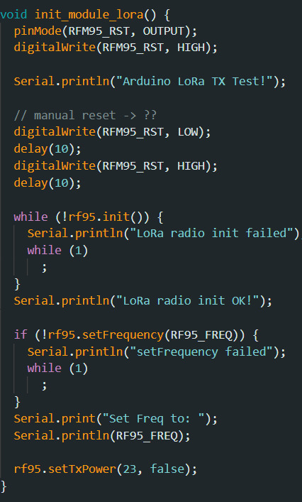
Transmetteur :

On définit les entrées de notre module et on effectue dans la partie setup, une procédure de test pour initialiser et connecter les deux appareils. Pour ce faire, on fixe la fréquence de transmission et de réception à la même valeur qui est ici 868MHz. On crée par la suite une données « data » qui nous donnera le nombre et les valeurs qui seront transmises. Comme on peut le voir à la fin de la partie setup, on rentre dans les « case » de data les valeurs à envoyé. Cependant, on ne peut obtenir que des nombres entiers !! Pour faire apparaitre des nombres décimaux, on écrit dans la data qui suit l’entier, sa valeur décimale comme par exemple:
data[3] = 12
data[4] = 4
On aura en résultat 12,4

Pour la partie Loop, on va écrire sur le moniteur série les « data » qui sont envoyées. Et c’est dans cette partie que nous écrivons les nombres décimaux en additionnant les valeurs de 2 « data ».
data[3] + ‘.’ +data[4] nous donnera en résultat 12.4
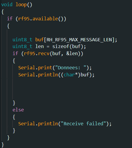
Récepteur :


Concernant la partie réception, on rentre la même fréquence de 868.0MHz. On définis nos entrées et sorties et on initialise comme pour le transmetteur. Cependant, dans la partie Loop, on va afficher sur le moniteur série les valeurs qui ont été transmises. Toujours sous forme de « data », nous les affichons une à une sauf pour les valeurs décimales. En effet, comme pour le transmetteur, on additionne les contenu de 2 « data » mais en plus on les divisent par 10.0 pour obtenir notre décimale.
Exemple :
Float val = data[3] + data[4] / 10.0;
On aura alors comme résultat affiché 12.4
On obtient alors en résultat sur le ports séries les données qui sont transmises mais aussi les données reçut écrit sous forme entière et décimale :


Module RTC + carte SD :
La carte SD est un élément dans lequel nos valeurs d’horodatages, de températures, niveau de batterie, autonomie restante et vitesse seront envoyées et enregistrées. L’horodatage permet de savoir en temps réel, le jour et l’heure précise à laquelle les données sont envoyées sur la carte. Il s’agit alors principalement de programmation bien que le module écarte SD soit relié au module Arduino.
Avant de programmer la carte SD, il faut un programme pour connaitre l’heure d’enregistrement des données. Pour ce faire, nous avons utilisé un module RTC qui fonctionne comme une horloge avec un pile.
Module RTC :


Ce programme est à faire une seule fois, le module sera alors autonome et nous implanterons une partie de son programme pour afficher l’heure et le jour dans la carte SD.
On a alors ici le programme permettant d’initialiser le module RTC avec comme information sur le port série:
Jour-Mois-Année, Heure:Minute:Seconde
Module SD :

La partie setup permet essentiellement de faire toutes les procédure pour savoir s’il est possible d’écrire sur un fichier dans la carte, en effet il cherche à savoir s’il y un un fichier crée ou non, si on peut écrire sur le fichier et surtout on ferme bien le fichier à la fin.

Concernant la partie Loop du programme, on récupère aussi dans les premières lignes une partie du programme du module RTC pour afficher l’heure et le jour sur le fichier carte SD mais aussi le moniteur série.
On retrouve le compteur qui va prendre 5 valeur avant de s’arrêter.
Dans cette partie on ouvre le fichier pour écrire les données que l’on souhaite à l’intérieur. Pour notre projet nous rentrerons en plus de l’horodatée, les températures, la vitesse, le niveau de batterie et l’autonomie restante. Ces actions sont possible grâce à la fonction « myFile.print(); ».
Les données sont enregistrées et envoyer sur un fichier Excel :

0 notes
Text
Séance 11 à l'IUT
Onzième séance :
Pour cette dernière séance voici les dernières tâches que nous devions réaliser :
Nous avons imprimés nos pièces en 3D pour faciliter l'implantation des capteurs et du tableau de bord sur le Kart.
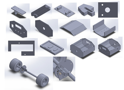
Sur cette photo on a le support pour le capteur de vitesse ainsi que le boitier du tableau de bord qui accueillera toute l'électronique embarquées. Il y a aussi la face avant permettant de mettre l'afficheur LCD, les leds, l'interrupteur et un switch pour le mode d'affichage. On a aussi le support pour la carte Arduino MEGA.
Pour de ce qui est le boitier de réception nous avons récupéré un boitier déjà existant à l'IUT.


Dans ce boitier on y trouve une carte Arduino avec un module LoRa pour recevoir les données.
Nous avons également imprimé une carte PCB pour le module LoRa du coté émission.


Cette carte permet de relier les pattes de LoRa que l'on utilise sur la carte MEGA.
On a également fabriqué un shield pour accueillir toute les connexions des capteurs et des différents modules.
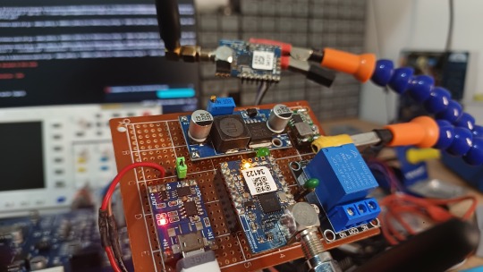
En cas de secours pour l'alimentation on a utilisé un Traco pour nous fournir différentes tensions dont nous avons besoins.
Voici le schéma eagle ainsi que le board :
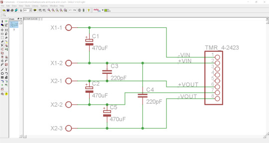
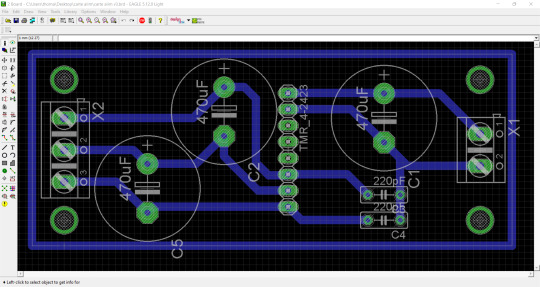
Cette petite carte doit permettre de nous fournir plusieurs tensions pour pouvoir alimenter chaque capteur ainsi que notre boite avec l'Arduino
On a également avancé le rapport de projet ainsi que le diaporama pour la soutenance.
0 notes
Text
Rowe ami jukebox 200 selection stereo

#Rowe ami jukebox 200 selection stereo generator
#Rowe ami jukebox 200 selection stereo drivers
#Rowe ami jukebox 200 selection stereo skin
#Rowe ami jukebox 200 selection stereo full
Videos relevant to "Model Railway Level Crossing": PIC12F617-I/P programmed for the Model Railway Level Crossing (Source component, AUD $10.00).Mechanical diagrams and label artwork for the Railway Level Crossing (PDF Download) (Panel Artwork, Free).Model Railway Level Crossing PCB pattern (PDF download) (Free).Firmware, source code and sound recording for the Model Railway Level Crossing (Software, Free).ISD1820-based voice recording and playback module (Component, AUD $7.50).Pair of PIC12F617-I/P chips for the Model Railway Level Crossing (Programmed Microcontroller, AUD $15.00).Model Railway Level Crossing PCB (AUD $5.00).Items relevant to "Model Railway Level Crossing": A Gesture Recognition Module (March 2022).Low-noise HF-UHF Amplifiers (February 2022).El Cheapo Modules: LTDZ Spectrum Analyser (January 2022).
#Rowe ami jukebox 200 selection stereo generator
El Cheapo Modules: 35MHz-4.4GHz Signal Generator (December 2021).
El Cheapo Modules: 6GHz Digital Attenuator (November 2021).
El Cheapo Modules: 3.8GHz Digital Attenuator (October 2021).
El Cheapo Modules: USB-PD Triggers (August 2021).
El Cheapo Modules: LCR-T4 Digital Multi-Tester (February 2021)Įl Cheapo Modules: USB-PD chargers (July 2021).
El Cheapo Modules: Mini Digital AC Panel Meters (January 2021).
El Cheapo Modules: Mini Digital Volt/Amp Panel Meters (December 2020).
New w-i-d-e-b-a-n-d RTL-SDR modules, Part 2 (June 2020).
New w-i-d-e-b-a-n-d RTL-SDR modules (May 2020).
El Cheapo modules: 8-channel USB Logic Analyser (February 2020).
El Cheapo modules: “Intelligent” 8x8 RGB LED Matrix (January 2020).
Three I-O Expanders to give you more control! (November 2019).
El Cheapo Modules: AD584 Precision Voltage References (July 2019).
El Cheapo Modules: Long Range (LoRa) Transceivers (June 2019).
El Cheapo Modules: Class D amplifier modules (May 2019).
#Rowe ami jukebox 200 selection stereo skin
El Cheapo Modules 23: Galvanic Skin Response (March 2019).
#Rowe ami jukebox 200 selection stereo drivers
El Cheapo Modules 22: Stepper Motor Drivers (February 2019).El cheapo modules, part 21: stamp-sized audio player (December 2018).El cheapo modules, part 20: two tiny compass modules (November 2018).El Cheapo modules Part 19 – Arduino NFC Shield (September 2018).El Cheapo: 500MHz frequency counter and preamp (July 2018).El Cheapo Modules 17: 4GHz digital attenuator (June 2018).El Cheapo Modules 16: 35-4400MHz frequency generator (May 2018).El Cheapo Modules 14: Logarithmic RF Detector (March 2018).El Cheapo Modules 13: sensing motion and moisture (February 2018).El Cheapo Modules 12: 2.4GHz Wireless Data Modules (January 2018).El Cheapo Modules 11: Pressure/Temperature Sensors (December 2017).El Cheapo Modules Part 10: GPS receivers (October 2017).El Cheapo modules Part 9: AD9850 DDS module (September 2017).El Cheapo Modules: Li-ion & LiPo Chargers (August 2017).El Cheapo Modules, Part 7: LED Matrix displays (June 2017).El Cheapo Modules, Part 6: Direct Digital Synthesiser (April 2017).El Cheapo Modules, Part 5: LCD module with I☬ (March 2017).El Cheapo Modules from Asia - Part 4 (February 2017).El Cheapo Modules From Asia - Part 3 (January 2017).El Cheapo Modules From Asia - Part 2 (December 2016).El Cheapo Modules From Asia - Part 1 (October 2016).
#Rowe ami jukebox 200 selection stereo full
You can view 0 of the 112 pages in the full issue.įor full access, purchase the issue for $10.00 or subscribe for access to the latest issues. This is only a preview of the July 2021 issue of Silicon Chip.
Notes & Errata: Advanced GPS Computer, June 2021 Mini Arcade Pong, June 2021 Refined Full-Wave Motor Speed Controller, April 2021 USB Flexitimer, June 2018.
Vintage Radio: The Rowe AMI JAL-200 jukebox.
Serviceman's Log: I’ve repaired planes before, but never tanks.
Project: Advanced GPS Computer – Part 2.
Project: Silicon Labs-based FM/AM/SW Digital Radio.
Circuit Notebook: Adding shuffle feature to low-cost MP3 player module.
Feature: El Cheapo Modules: USB-PD chargers.
Feature: How USB Power Delivery (USB-PD) works.
Publisher's Letter: Software: too many bugs, too many updates.
0 notes
Text
IoT Standards & Protocols Guide - Arya College

The essence of IoT is networking that students of information technology college should be followed. In other words, technologies will use in IoT with a set protocol that they will use for communications. In Communication, a protocol is basically a set of rules and guidelines for transferring data. Rules defined for every step and process during communication between two or more computers. Networks must follow certain rules to successfully transmit data.
While working on a project, there are some requirements that must be completed like speed, range, utility, power, discoverability, etc. and a protocol can easily help them find a way to understand and solve the problem. Some of them includes the following:
The List
There are some most popular IoT protocols that the engineers of Top Engineering Colleges in India should know. These are primarily wireless network IoT protocols.
Bluetooth
Bluetooth is a wireless technology standard for exchanging data over some short distances ranges from fixed and mobile devices, and building personal area networks (PANs). It invented by Dutch electrical engineer, that is, Jaap Haartsen who is working for telecom vendor Ericsson in 1994. It was originally developed as a wireless alternative to RS-232 data cables.
ZigBee
ZigBee is an IEEE 802.15.4-based specification for a suite of high-level communication protocols that are used by the students of best engineering colleges to create personal area networks. It includes small, low-power digital radios like medical device data collection, home automation, and other low-power low-bandwidth needs, designed for small scale projects which need wireless connection. Hence, ZigBee is a low data rate, low-power, and close proximity wireless ad hoc network.
Z-wave
Z-Wave – a wireless communications protocol used by the students of Top Information Technology Colleges primarily for home automation. It is a mesh network using low-energy radio waves to communicate from appliance to appliance which allows wireless control of residential appliances and other devices like lighting control, thermostats, security systems, windows, locks, swimming pools and garage door openers.
Thread
A very new IP-based IPv6 networking protocols aims at the home automation environment is Thread. It is based on 6LowPAN and also like it; it is not an IoT protocols like Bluetooth or ZigBee. However, it primarily designed as a complement to Wi-Fi and recognises that Wi-Fi is good for many consumer devices with limitations for use in a home automation setup.
Wi-Fi
Wi-Fi is a technology for wireless local area networking with devices according to the IEEE 802.11 standards. The Wi-Fi is a trademark of the Wi-Fi Alliance which prohibits the use of the term Wi-Fi Certified to products that can successfully complete interoperability certification testing.
Devices that can use Wi-Fi technology mainly include personal computers, digital cameras, video-game consoles, smartphones and tablets, smart TVs, digital audio players and modern printers. Wi-Fi compatible devices can connect to the Internet through WLAN and a wireless access point. Such an access point has a range of about 20 meters indoors with a greater range outdoors. Hotspot coverage can be as small as a single room with walls that restricts radio waves, or as large as many square kilometres that is achieved by using multiple overlapping access points.
LoRaWAN
LoRaWAN a media access control protocol mainly used for wide area networks. It designed to enable students of private engineering colleges in India to communicate through low-powered devices with Internet-connected applications over long-range wireless connections. LoRaWAN can be mapped to the second and third layer of the OSI model. It also implemented on top of LoRa or FSK modulation in industrial, scientific and medical (ISM) radio bands.
NFC
Near-field communication is a set of communication protocols that enable students of best engineering colleges in India two electronic devices. One of them is usually a portable device like a smartphone, to establish communication by bringing them within 4cm (1.6 in) of each other.
These devices used in contactless payment systems like to those used in credit cards and electronic ticket smartcards and enable mobile payment to replace/supplement these systems. Sometimes, this referred to as NFC/CTLS (Contactless) or CTLS NFC. NFC used for social networking, for sharing contacts, videos, photos,or files. NFC-enabled devices can act as electronic identity both documents and keycards. NFC also offers a low-speed connection with simple setup that can be used by the students of top btech colleges in India to bootstrap more capable wireless connections.
Cellular
IoT application that requires operation over longer distances can take benefits of GSM/3G/4G cellular communication capabilities. While cellular is clearly capable of sending high quantities of data. Especially for 4G with the expense and also power consumption will be too high for many applications. Also, it can ideal for sensor-based low-bandwidth-data projects that will send very low amounts of data over the Internet. A key product in this area is the SparqEE range of products including the original tiny CELLv1.0 low-cost development board and a series of shield connecting boards for use with the Raspberry Pi and Arduino platforms.
Sigfox
This unique approach in the world of wireless connectivity; where there is no signalling overhead, a compact and optimized protocol; and where objects not attached to the network. So, Sigfox offers a software-based communications solution to the students of top engineering colleges in India. Where all the network and computing complexity managed in the Cloud, rather than on the devices. All that together, it drastically reduces energy consumption and costs of connected devices.
SigFox wireless technology is based on LTN (Low Throughput Network). A wide area network-based technology which supports low data rate communication over larger distances. However, it mainly used for M2M and IoT applications which transmits only few bytes per day.
0 notes
Text
Suitable for Arduino 3.3V RFM95 RFM69CW RFM12 RFM69HCW RFM92 RFM98 RFM96 Wireless LoRa module development board
Suitable for Arduino 3.3V RFM95 RFM69CW RFM12 RFM69HCW RFM92 RFM98 RFM96 Wireless LoRa module development board

lastest_volume
87
Just For Today
Click Here To Visit The Shop
N€W Suitable for Arduino 3.3V RFM95 RFM69CW RFM12 RFM69HCW RFM92 RFM98 RFM96 Wireless LoRa module development board
0 notes
Text
Leitura analógica do LoRaMesh da Radioenge
Aprenda como usar a leitura analógica com o módulo LoRaMesh da Radioenge
A leitura analógica com o LoRaMesh possibilita com que possamos fazer um amplo sistema de sensoriamento remoto sem precisar necessariamente de microcontrolador adicional na parte do slave. Por qual motivo usar a leitura analógica do LoRaMesh da Radioenge? Uma leitura digital em muito dos casos já é mais que o suficiente para saber se algo está ou não funcionando, mas a leitura analógica do…
View On WordPress
#lora mesh arduino#lora mesh chat#lora mesh device#lora mesh library#lora mesh module#lora mesh network#lora mesh network raspberry pi#lora mesh protocol#lora mesh radio#lora mesh range#lora vs lorawan#loramesh#lorawan#lorawan devices#lorawan gateway#lorawan network#mesh lora
0 notes
Photo

Hello dear friend, that's esp32+lora #Heltec module. #esp32 + #lora But the range is about 50 meters. More 🔭 @aelmaker . . #esp32 #diyelectronics #electronics #arduino #makers #украина #ukraine #diy #prototype #aelmaker #электроника #homemade #electronics #arduinomega #18650 #diyprojects #lorawan #lora (New Mexico) https://www.instagram.com/p/CO8fEpPrg4j/?igshid=1edjhh5i2hipa
#heltec#esp32#lora#diyelectronics#electronics#arduino#makers#украина#ukraine#diy#prototype#aelmaker#электроника#homemade#arduinomega#18650#diyprojects#lorawan
0 notes
Text
Séance 10 à l'IUT
Dixième séance :
Finalisation de tout nos modules arduino. Durant cette séance nous avons terminés les 4 fonctions qui constitue notre système d'implantation sur le Kart. La fonction mesures, affichages, stockage et transmission.
Durant cette séance nous avons finalisé la fonction transmission avec le module Arduino LoRa.
Pour ce faire nous avons du faire deux programmes, premier consiste à envoyer nos données et le second permet de les réceptionner et de les afficher sur le port série du PC.
Voici le module LoRa :

Ce module est directement implanté sur la carte MEGA . Nous avions du connecter correctement les pattes MISO, MOSI et SCK à l'aide de câble car les pins de la LoRa ne sont pas reliées au bon endroit sur la carte MEGA. Pour palier ce problème de fil nous avons crée un Shield sur la Lora en circuit imprimé que voici :
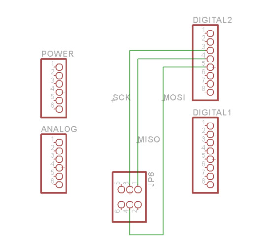
Schéma Eagle.
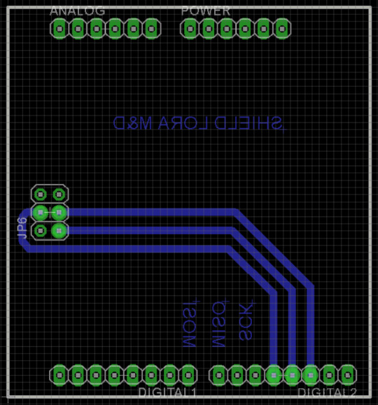
Board eagle.
Voici la partie programme permettant de recevoir les données :
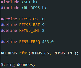
Dans cette partie nous définissons nos variables. Nos données nous allons les recevoir en chaine de caractères. On définit les pattes du SPI qui sont la 10, 9 et 2. On règle notre fréquence de transmission et de réception à 433 Mhz.
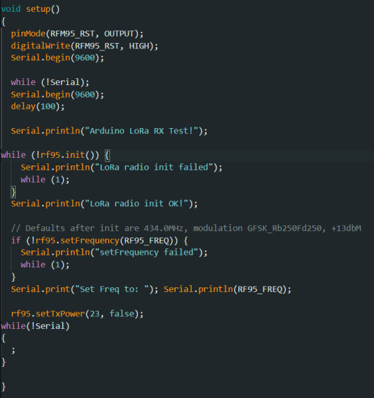
Dans la partie Setup on va initialiser le module et paramétrer la connexion des deux modules.
Dans la Loop nous allons venir récupérer nos données en chaine de caractères et les afficher sur notre moniteur série.
Voici maintenant la partie programme pour le transmetteur :
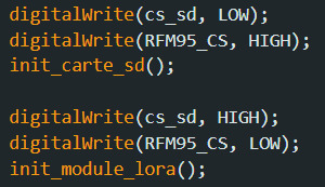
Dans la partie Setup on va initialiser nos modules qui fonctionnent en SPI pour ne pas avoir d'interférence, en l'occurrence le module de LoRa et la carte SD. On choisit à qui on va s'adresser. Ces paramètres là sont rajoutés juste devant l'initialisation de chaque module dans la partie Setup.
Voici la partie initialisation du module de transmission qui est quasiment identique à la partie initialisation du module de réception.
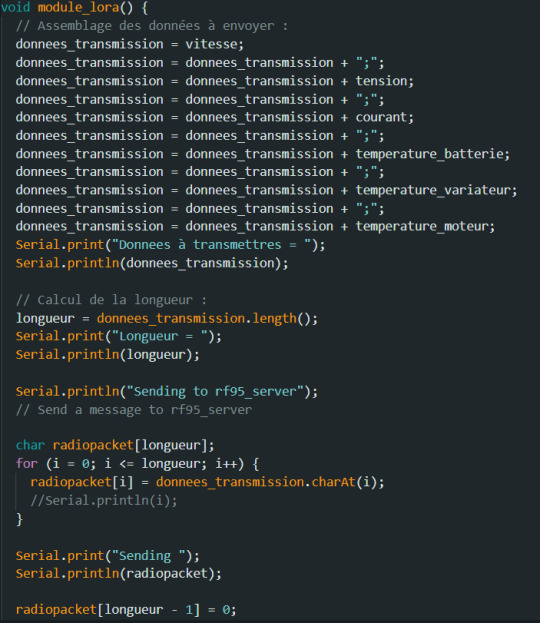
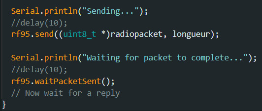
Dans cette partie de programme on vient mesurer la longueur de notre chaine de caractères. On utilise la fonction charAt qui nous permet d'envoyés des variables en caractère. Dans le début du programme on récupère nos données qui sont aussi stocker sur carte SD et on les envoies directement à notre module de réception.
Voici le résultat de la réception :
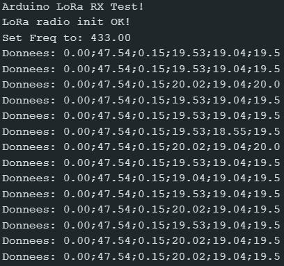
On peut observer dans la première colonne la vitesse qui est nul, ensuite la tension, le courant et les 3 capteurs de températures.


Une fois toute cette partie terminée, il faut qu'on modélise nos boite en 3D pour ranger notre électronique, faire le tableau de bord et fabriquer une carte en circuit imprimée pour toute nos connectiques.
NE PAS OUBLIER DE RACHARGER LES BATTERIES POUR LA PROCHAINE FOIS !!!!
0 notes