
Don't wanna be here? Send us removal request.
Statistics
We looked inside some of the posts by bijliwala and here's what we found interesting.
Average Info
Notes Per Post
1
Likes Per Post
1
Reblog Per Post
0
Reply Per Post
0
Time Between Posts
11 days
Number of Posts By Type
Text
17
Last Seen Tumblr Blogs


Fun Fact
Tumblr Inc. is using 66 technologies for its website.
Text
Understanding Fork Type Photo Electric Sensors for Labels
Label is a type of paper which is printed on something Which gives information about it. Pasting a label on a material is not a tough task But In industry where production is happening in millions. Label pasting process requires heavy man-power & heavy investment. But with the help of automation, Label pasting process can becomes easy & fast. Automation also reduces the man-power & Chances of…
0 notes
Text
Understanding Voltage: AC vs DC Explained
In Electrical, Voltage is an Electrical pressure behind the flow of Electrical current. Volt(V) is the unit of Voltage. 1 Volt represents the Electrical pressure needed to get a flow of 1 amp of Electrical current around the resistance of 1 ohm. Potential difference between two nodes V1 & V2 is V1-V2 Voltage is actually a potential difference between the two nodes. Work done or we can say, A…
0 notes
Text
Star-Delta Starters, Its key diagram & Working !
A Brief description of Star-delta starter, Its importance, Its components & Its wiring.
Most industrial motors are Induction motors. Thus, it is important to study every aspect of an induction motor, Such as its starting, running, and protection. Starters not only starts the motor but it provides protection to the motor in overload & phase loss conditions. For small rating motors, DOL starters can be employed. But for large rating motors, DOL is not a good choice. This is…
0 notes
Text
Cyclic Timer XC800
This timer operates in an alternate manner such that ON,OFF,ON,OFF,ON,OFF . . Both the ON&OFF timing can be adjusted. In along, Which Timer is going to operate first; ON delay or OFF delay; is all selectable.

FEATURES
Finger safe Terminals.
Universal power supply AC & DC ranges from 20 to 240 Volts.
6 Time ranges 0-1 sec,0-1 Minute, 0-1 Hour, 1-10 secs., 1-10 Minutes, 1-10 Hours.
2 Changeover Relays.
LED indications for power & relay ON.
Uneven ON & OFF times. Both the ON & OFF timer’s ranges are individually selectable.
There is selection which timer is going to operate first.
0 notes
Text
OVERLOAD IN ELECTRICAL SYSTEM
Overload as name reflects; Defines the excess level more than the capacity.
Similarly, In Electrical, Overload defines Electrical load consuming higher current more than the rated capacity.
To derive any type of electrical load, It should be connected with the rated voltage supply & then it consume current as per according to its capacity.
Voltage remains the same across different types of loads. However, the level of current depends on the power rating of the load. That's why back-end fuses and power cables are designed according to the rated current. They are also designed by considering the fault current situations.

0 notes
Text
FREQUENCY IN ELECTRICAL SYSTEM
There are two types of power supplies; AC & DC. Both the supplies have common terms voltage and current. However, one term creates a difference between the two. That term is “frequency“.
In general, Frequency means something happening continuously & symmetrically. In Electrical, Frequency of power supply defines how many cycles are occurring per second.
DC stands for Direct current. As name suggests, DC remains direct or constant at its magnitude with respect to time. AC stands for Alternating current. While moving, AC changes its direction continuously at fixed intervals. Both the phenomenon’s are visualized through a GIF below:
GIF below shows the waveform of Direct current. It moves with respect to time at a fixed magnitude. It does not change its direction.

Gif of alternating current below. It represents a sinusoidal waveform moving with respect to time. It also changes its direction. Actually, It has two halves, One is positive While another one is negative. Both the halves in complete represents one cycle.

FREQUENCY
Frequency of power supply defines how many cycles are occurring per second. The sinusoidal AC waveform continuously changes its direction. This change makes cycles continuous. This means AC power has the term frequency, while DC does not. In India, Power frequency standard is 50 Hz While in USA power frequency standard is 60Hz.
A connected image below shows the AC sinusoidal waveform with having a frequency of 3 Hz.

FREQUENCY
0 notes
Text
FALL OF POTENTIAL METHOD OF EARTH TESTING
There are multiple methods of Earth testing with multiple digital devices. In this post, most basic & old method of earth testing is going to be discussed which is fall of potential method. The idea behind this method is, A resistance value From a bottom tip of earthing up to minimum straight distance of 20meters is been monitored. That resistance value is been considered as its resistance value. For better discussion about this testing, Digital Earth Resistance tester by WACO is used.

This device contains four terminals E1,P1,P2,E2. E1 & E2 terminals are current terminals While P1 & P2 are voltage terminals which detects potential difference. This device has 2 range selections 10Ω & 1000Ω. For starting the test, A test button is provided.
In this method, 2 Earth spikes are used Which are buried in soil with equal distances from main earth electrode. Both the spike are aligned in same line, Such that it becomes line of three In which Main earth electrode is first while 1st spike is buried with a minimum distance of 20 meters from main earth electrode while 2nd spike is buried at a distance of 20 meters from 1st spike. As shown in an image below: Arrangement of Earth spikes in fall of potential method
0 notes
Text
How PT-100 Sensors Work: A Comprehensive Guide
PT-100
PT-100 sensors are type of RTD. And RTD stands for ‘Resistance temperature detector‘. As name describes, These sensors are used to detect the temperature. These sensors are available in 3 & 4 wires & having a measuring range of -200°C to 500°C.

WORKING OF PT-100 TEMPERATURE SENSOR
These sensors actually follows the stable temperature & resistance relation Whose resistance value increases as temperature increases.
These sensors mainly contains metallic element such as platinum Which Enclosed inside the metallic or glass tube. Enclosed metallic element follows temperature-resistance relation in direct proportion. It’s resistance value increases as temperature increases. For resistance measurement, Wires are connected to this metallic element.
Sensors wires are further connected to Microcontroller through thin wires. Microcontroller continuously monitors the resistance value. Particular temperature has fixed resistance value. Such that; At 100°C resistance valve will be 125ohm While at 0°C value will be 100ohm.
Resistance & temperature proportion data is saved in microcontroller. As per according to stored program & Current resistance value, Controller displays the temperature.

1 note
·
View note
Text
Understanding the Electrical Insulation
Electrical Insulation is a type of resistive layer Which offers very high resistance more than conductors & semiconductors.
Insulations are either used as a layer around the potential carrying conductors or as a medium or as a separation or as a Base for conductive elements.
Ceramic, Glass, PVC, Bakelite are some of the materials used in insulation.
Insulation & Conductors, Both works Hand in Hand; Both are equally important.
Under the voltage rating; Insulation completely restricts the flow of current But higher voltage beyond a certain limit can damage the insulation & current get pass easily through it & That's voltage is known as breakdown voltage for that insulation.
Special devices such as meggar & digital insulation testers are used to measure insulation resistances.

0 notes
Text
Insulation monitoring device; Isometer IR425 by BENDER
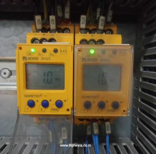
This device specially designed for 2 wires AC-DC System up to 300Volts. 2 power lines of the test specimen & earth line get connected across the device. A Digital display is been provided Which continuously displays the present insulation resistance. With the help of keypad, parameters value can be reset easily.BENDER'S ISOMETER IR425
This device, At regular intervals or When it get energized or When a test button is pressed, Generates the pulse voltage in the system to monitor the present insulation resistance irrespective of Whether the system is energized or not. In system's running condition, device's signal get superimposed on the system's signal.
When present value falls below the set range, After the set delay time, Relay get operated in along with the LED Indication. Two separate relays are provided which can be used as pre-alarm or final- alarm on different insulation standards.
As it is monitoring two terminals resistance, It also indicates which side's insulation value get lowered. If the fault memory is enabled, The alarm remains activated until the reset button been pressed or power supply goes off.
For a testing, A test button is provided on the device.
0 notes
Text
VFD (VARIABLE FREQUENCY DRIVE)
A VFD is a type of device; equipped with power electronics.
VFD takes normal rated power supply as an input & produces an output variable supply with variable voltage & frequency As per according to feed parameters.
By changing the voltage & frequency input to the motor; It changes the speed of the Electrical motor.
* An image attached below shows the different section of VFD .
A red rectangle doodle shows the input terminals.
A green rectangle doodle shows the output terminals.
A orange rectangle doodle shows the control terminals.
A blue rectangle doodle shows CAT-6 jack for HMI

15KW 3phase 400VAC by ABB
HOW DOES THE VFD WORKS ?
Synchronous Speed formula is, Ns=120f/P
Where f is frequency ; P is the pole of motor winding
// When P is 4 & f is 50Hz
Than Ns becomes= 1500 RPM
// When P is 4 & f is 60Hz
Than Ns becomes= 1800 RPM
// When P is 2 & f is 50Hz
Than Ns becomes; 3000RPM
// When P is 2 & f is 60Hz
Than NS becomes; 3600 RPM
Clearly seen in the formula above, By changing the winding poles & frequency; Speed can get adjusted. In fixed winding electrical motor, It is quite difficult to change the poles of the winding. Now Only option that left is; Frequency.

VFD display shows the frequency 17.85Hz 4KW 3phase 400VAC VFD by invt
Before further understanding of VFD working mechanism, We should know about the frequency first !
0 notes
Text
MCB current Rating
It is the current upto which MCB works precisely without getting trip.
An image1, Rated Current is 32Amps.
An image2, Rated Current is 63Amps.
As discussed above, MCB provides protection in Overload & Short circuit conditions.
Overload- It is the Phenomenon in Electrical system in which current flows more than the rated capacity of the component. It is generally a slow process phenomenon.
Short Circuit- It is the rapid phenomenon in which current rises exponentially, uncontrollably in undefined direction. Short circuit situation has much larger current As compare to overload which can be multiple times the rated current of the system.EXAMPLELet suppose we have 2pole C32Amps MCB@Total 3 Loads are connected across it which are taking current as 10Amps,10Amps & 5Amps in total current 25Amps. System will work smoothly.
// Now another load get connected across it which is taking current 15Amps which results total current across MCB will be 40Amps which is more than the rated capacity of MCB. After sometime under total load of 40Amps, MCB get trips. This situation is known as overload.
// Now let suppose, potential wire get shorted with earth or neutral directly. At this situation heavy current flows rapidly which is multiple times more than the rated capacity of the MCB. This situation is known as short circuit. MCB will trip instantly.
MCB current rating should be selected on two factors; load current & type of load. Generally, we do choose MCB rating atleast 1.5 times of the load current. So that even in surge current position at the initial time of switching, MCB do not trips. Example 1.5 KW 3phase Induction motor with Rated current of 3Amps. We do choose a MCB of minimum 6Amps.

0 notes
Text
Alternator- Generating Alternating Current
Alternator is a type of machinery which converts mechanical power into an Electrical power. A mechanical power means such as Diesel Engine, Petrol Engine, Turbine, Bio Fuel Engine; Which produces mechanical power; connects Infront of the alternator. Then alternator converts mechanical power into Electrical power. The Electrical power generated by the alternator; is a type of Alternating current, That's Why known as 'ALTERNATOR'.
WORKING PRINCIPLE OF ALTERNATOR
An Alternators works on the principle of faraday law of Electromagnetic Induction Which states that; A changing magnetic field linking with the conductor; creates an EMF.
" A GIF attached below clearly explained the working of Alternator. At Starting, Rotor is standstill. There is no emf in Rotor & Stator. When rotor starts rotating; It get excited through some sort of means Which results Rotor's winding becomes electromagnet Whose magnetic field continuously changing with respect to the stator.
That changing magnetic field continuously linking to Stator's winding Which results an EMF get generated in Stator's winding. "

0 notes
Text
Types of Temperature Controllers
Temperature Controllers are classified in two categories, One is Basis of control & Second one is Basis of process. On basis on control, Temperature controller has two types which are ON-OFF control & PID Control. On basis of process, Temperature Controller has three types which are heating, Cooling & Heating+ cooling(process control)

0 notes
Text
Process Controllers
Process controllers are the combination of heating & cooling processes which manages the temperature at particular level by connecting or disconnecting heating or cooling element.

0 notes
Text
Temperature Controllers
Temperature controller are electronic devices equipped with microcontroller. These temperature controllers with the help of input temperature sensor continuously monitors present temperature of the system than controller compares the present value with the set/target value. If there is error in between present value & set value than by connecting or disconnecting heating or cooling element, it maintains the temperature.

0 notes
Text
REED SWITCH
Reed switch also known as 'Reed sensor' & 'Magnetic sensor'. These sensors contains contact made with metallic ferromagnetic material which act as a magnetic switch. Sensor's contact changes its state in the presence of magnetic field. While moving away from magnetic field, the contact of this sensor get back to its normal state As shown in an image below.

0 notes