
everettstaley
Everett Staley
Design, Writing, and Projects
5 posts
Don't wanna be here? Send us removal request.
Last Seen Blogs

angusfoxley-blog
Untitled

poven-goh
Untitled

5sosfanfictioncatalogue
5sos Fanfiction Catalogue

sakkakun
single light

very-normal-hatchetfield-girl
local Hatchetfield cryptid
Video
youtube
Flexible Phone Holder, Continued...
Progress is slow! I had to ditch the Pneumatique filament- clogs were too frequent. So I'm using MH Build TPU, and that's working fine. I've gone through a few iterations of what I was calling the "dogbone," but am now calling the "molecule," the basic building unit of the tripod. Mostly, it's a matter of getting the opening size of the socket juuuuuust right. Too small, and one can't put them together, or even if they go together, they don't articulate enough. Too large, and they come out too easily and/or don't hold their articulation.
Here's a video of my design process for the molecule.
I also tried printing with Cura's "fuzzy skin" experimental feature to see if that would improve the ability for the molecules to hold their position: it did! So what I really should do is fuzzify the skin in blender...
My 3D printer is currently engaged in a rather long, time-sensitive project, so I have been stalled on the flexible phone tripod project. I've got a design for the phone holder and for a multi-socket piece to join the legs and holder, but I haven't been able to test those yet, so I am not ready to post them over on cults3d. Those will be the next step though!
#3d print#3d model#3d#design#cura#blender#spheres#phone#tripod#holder#articulated#ball and socket#joint#diy#practical#useful#tpu#flexible#filament#youtube
0 notes
Text
Flexy Phone Tripod, Step One
I'm kind of reinventing the wheel here, because there are a few 3D printable phone tripods out there, even ones using the flexible ball 'n socket legs.
I didn't find any, however, that were completely 3D printed, so that's my goal.
Like every project, it's taking longer than expected! So instead of writing out the whole process, this will be the first part in a small saga of tripod building, in which I design what I call the "dogbone." The dogbone will be the little ball and sockets that fit together just right to make the legs flexible, but stiff enough to hold their position. I expect they will take a couple iterations to get right. Once they are right, however, they make for a cool modular system- the legs can be extended or shortened by adding or removing segments, and other gadgets can be added just by printing something with the right size ball on one end.
Here's my rough sketch to start with-

And here's the first iteration of the dogbone in Blender.

I'm a little concerned that I made the hole on the open circle big enough. I'm printing the first two right now to test it. In any case, now that I've got the idea down, it shouldn't be difficult to tweak. I just joined two mesh spheres with a cylinder, cut one, flipped the inside, and joined the edge loops to make it a solid hollow sphere instead of a single walled mesh. The whole sphere I shrank slightly so it will fit inside the cut sphere.

This is also an opportunity to use a new filament that I'm excited about. It's my first flexible filament, called Pneumatique by Treed. It's made from recycled car tires! I've so far printed my maker coin and a very squishy benchy with success. It's not the easiest filament to use, as it's prone to clogging, but Treed recommends a 0.5mm nozzle, and I'm using a 0.4mm, so I can't blame them. I've just had to run the nozzle at 240C and keep my printing speed very slow, below 30mm/s.
It smells like burning tires, so ventilation is probably a good idea. But it prints nicely once you've got it down, and the layer adhesion is fantastic. It is very textured. I'm looking forward to printing some custom gaskets and replacement tool handles with it.
https://treedfilaments.com/3d-printing-filaments/pneumatique-recycled-car-tires-3d-filament/


That's it for phase one! I'll update with the success or failure of the dogbone design, and then phase two!
#diy#3D printing#3D design#recycled#rubber#tires#filament#prototyping#smartphone#tripod#flexible#squishy#benchy#treed#pneumatique
0 notes
Text
youtube
Making videos is hard!
In this one I explain why I'm not a YouTuber. I am planning to make some videos, but they're going to be sporadic and cover a variety of topics.
0 notes
Text
How to Get Real-World Shapes (especially weird ones) Into the Computer for 3D Printing
Many 3D printers end up used mostly to create knick-knacks, though we justified buying the machine with all the useful stuff we could make! One of the reasons for this is that Baby Yoda’s dimensions aren’t exactly critical to it’s purpose, but the broken knob you wanted to replace has a weirdly shaped fitting that won’t work unless it’s just right, and how do you measure that? Then how do you design something to fit it?
There are a few methods! What follows is my low-cost, low-math method for replicating weird shapes for 3D printing.
You’ll need: the part you want to work with, paper large enough to cover it, a pencil, a ruler (the finer the measurement, the better), your 3D design software of choice, and your slicer.
For my example, I needed to make porthole trim rings with a lip. My boat had 10 portlights with beautiful cast bronze trim rings on the hull, but on the stern it had four strangely shaped holes cut roughly, exposing the edge of the plywood.

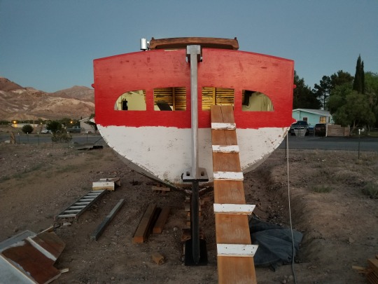
I taped paper over the portholes, and traced the outline from the inside. If you’re working with a small piece or can’t get inside the thing for whatever reason, take a rubbing by rubbing the side of a pencil lead or a crayon on the paper where the edges of the object are. The edges should come out clearly enough to take measurements from. Then, draw a grid on your tracing or rubbing.
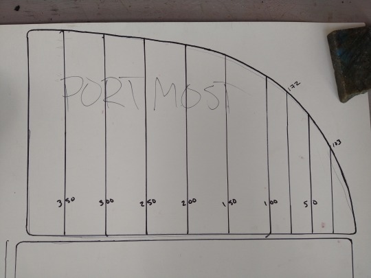
The more curved your piece is, the more reference lines you’ll want in your grid. This piece had a nice right angle with two flat sides to reference, but if yours doesn’t, just extend the lowest and leftmost parts of your piece so they meet at a right angle, and build your grid from there.
This is how I gather measurements to input into a 3D design program- how you input them will depend somewhat on your program of choice, and I’ll save an in-depth description of that for a later post. Here’s how the rest of this project went, though.
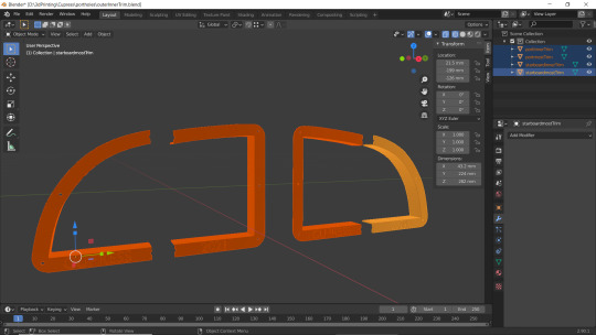
I created a rectangle in Blender, then used the slice tool to create vertices at each of my measured distances from the y axis (Fusion 360 is more optimized for dimensional design, but Blender can do it and is open source). In Blender, you can make a slice and then input the exact measurement for its placement. Then I did the same from the x axis. That placed vertices at the measured points along the curve of my object. Deleting faces from the rectangle and joining vertices into new faces “carved” the basic shape from my rectangle, and then I mostly used the extrude tool to get my final shape.
Turn on mirroring to save yourself time if it applies to you, but also pay attention to when to turn it off! For me, I created the object, but turned off mirroring to emboss the words I wanted into the design. Your slicer can be a good tool for checking whether your design is “manifold.” Usually it’ll highlight the areas that aren’t, and show an error. Sometimes you can print even if it isn’t manifold, but it’s best practice to fix it, because it can affect printing in unpredictable ways.
I printed a prototype in cheap, recycled PTEG.


Then in bronze filled filament from Protopasta!
https://www.proto-pasta.com/collections/all/products/bronze-metal-composite-htpla?variant=7154346098733

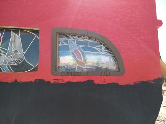
This filament has so much bronze in it that it will patina like bronze, and can even be polished. It isn’t cheap, but this was much more doable for me than casting from real bronze, and having all four portlight rings custom cast would have been over a thousand dollars.
#3D printing#3d design#diy#product design#design#design process#measurements#protopasta#portlight#boat#woodenboat#budget#Blender#Fusion360#Cura#slicer#3D printer#3D#window#sailboat#liveaboard#crafting#self sufficiency#weird shapes#dimensions
3 notes
·
View notes
Text
To build a better... cup holder.
The design brief:
- Hold cups
- Stay upright in a moving vehicle
- 3D print in one piece
The short version: A gimballed cup holder that can be 3D printed in place and mounted in a boat or other vehicle.
Thingiverse: https://www.thingiverse.com/thing:4790500
I was inspired by this:

https://www.boatandrvaccessories.com/image?filename=11670-4.jpg&width=580&height=0
But I thought I could improve upon the design while trying out Fusion 360 and my new Snapmaker 3D printer. My version would cost me little, and printed in brass or bronze filament, would match my boat better.
Starting as usual with a napkin sketch, I didn’t change much in concept from the original. I added a slot for a coffee mug’s handle and integrated the mounting bracket for strength and simplicity.

My next step was to decide upon dimensions. I measured my favorite coffee mug, and then several others just to make sure more would work.
Dimensions in hand, I dove into YouTube for some tutorials on Fusion 360. Nearly everything I needed for this project I found in the Maker’s Muse makercoin tutorial here: https://youtu.be/UytkIrXxVvE. The other searching I did was on joints, which wouldn’t be necessary for printing, but I wanted to be able to model the actual movement of the joints in Fusion 360.

With a basic model created, I tried a few aesthetic variations. The bottom needed holes for drainage, and I took the opportunity to incorporate my logo. The solid wall wasn’t necessary for strength, so I played around with perforating it until I found an arrangement to my liking.
I exported the .stl from Fusion and loaded it into Cura, where I enabled supports (for the bracket), set the heated bed to 60 C, the nozzle to 215 C (on the hot end of the recommended temperature to encourage layer adhesion), and the layer height to .24 (optimal strength for a .4mm nozzle, according to CNC Kitchen’s test video on YouTube: https://youtu.be/fbSQvJJjw2Q).
Then, using the sample white PLA filament that came with my printer, I set the Snapmaker to print overnight! I sat and watched the first few layers go down before going to bed, partly out of caution and partly because 3D printing round objects is especially mesmerizing.
Here is the final result! I’ll add a video of it in action when I can take my boat sailing.
#3D printing#3d design#product design#snapmaker#cupholder#coffee#sailing#sailboat#diy#fusion360#cura#pla
2 notes
·
View notes