#Arduino Plotter
Explore tagged Tumblr posts
Visit Tumblr Blog
Explore Tumblr blogs with no restrictions, modern design and the best experience.
Last Seen Tumblr Blogs


Fun Fact
Mobile Tumblr US users spend an average of 4.04 minutes per session on the app.
Text
Franzis Adventskalender für Arduino - Tag 1

Heute starten wir mit dem ersten Tag des Franzis Adventskalender für Arduino.

Franzis Adventskalender für Arduino - Tag 1 Öffnen wir nun also das erste Türchen. Hinter dem ersten Türchen verbirgt sich ein Arduino Nano V3.


Im Handbuch finden für zum Tag 1, wie man diesen Mikrocontroller einrichtet und die Arduino IDE installiert. Was du noch benötigst, ist ein Micro-USB Datenkabel für die Verbindung zum PC.
Einrichten auf einem Windows-PC
Eigentlich verbindet man den Mikrocontroller nur mit dem PC und dann wird dieser sogleich eingerichtet. Eigentlich! In meinem Fall hat sich der PC mit einem Bluescreen verabschiedet und einer IRQ Meldung, d.h. eigentlich nur das dieser Mikrocontroller einen IRQ belegen wollte, welcher bereits belegt oder reserviert ist. Okay kann passieren, Windows halt, also einmal neu starten und ein zweiter Versuch. Nun hat es funktioniert und der Mikrocontroller wurde im Geräte-Manager erkannt.
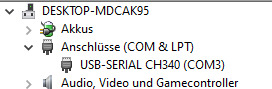
Windows Gerätemanager - Arduino Nano von Franzis Da ich bereits mit einigen Mikrocontrollern gearbeitet habe und somit diverse Treiber bereits installiert habe, entfiel der Schritt zum Installieren des seriellen Treibers für den CH340G Chip.
Aufbau des Arduino Nano
Auf dem Markt gibt es diverse Arduino Nano Klone (wie auch dieser hier von Franzis), was allen ziemlich gleich ist, dass diese dasselbe Pinout haben.
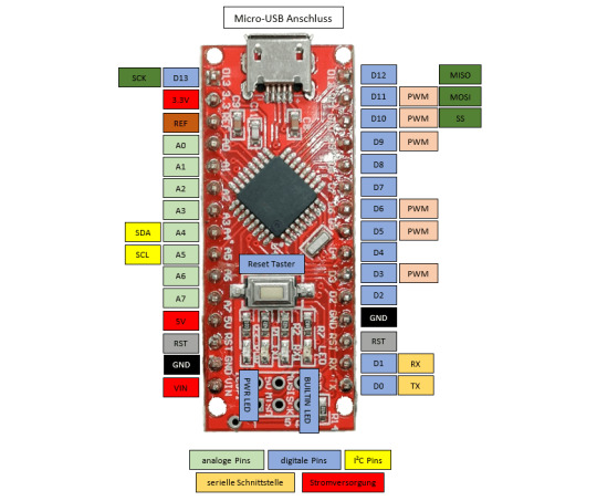
Pinout - Arduino Nano V3
Technische Daten des Arduino Nano V3
Den Arduino Nano habe ich bereits in sehr vielen Beiträgen auf diesem Blog verwendet und dir auch im Beitrag Arduino Nano – Übersicht dir diesen bereits vorgestellt. Auf dem Board ist ein ATMEL MEGA328P verbaut.

Hier nun der Vollständigkeit halber die technischen Daten zu diesem Mikrocontroller: Länge45 mmBreite18 mmGewicht7 gFlash Speicher32 KB (von denen 2 KB für den Bootloader reserviert sind)SRAM2 KBEEPROM1 KBCPU Taktgeschwindigkeit16 MHzBetriebsspannung5 VEingangsspannung7 V bis 12 VStromaufnahme19 mAmax. Stromstärke pro I/O Pin40 mAdigitale Eingänge / Ausgänge22digitale PWM Ausgänge6analoge Eingänge / Ausgänge8
Installieren der Arduino IDE 2.0
Im Handbuch wird die Arduino IDE in der Version 2.0.0 Beta-3 dargestellt, mittlerweile haben wir eine offizielle Version zur Verfügung. Diese beiden Versionen sind vom Aufbau her sehr unterschiedlich, daher zeige ich dir in den nächsten Tagen, wie die Schaltungen in der neuen Version programmiert werden.
Arduino IDE 2.0.0 Die aktuelle Version kannst du unter https://www.arduino.cc/en/software herunterladen, die Installation ist denkbar einfach, denn man muss lediglich dem Wizard folgen.
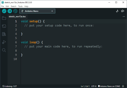
Aufbau der Arduino IDE
Die Arduino IDE hat eine Toolbar, in welcher du die Schaltflächen findest, welche du wohl am meisten benötigst.

v.l.n.r: - Verify, - Upload, - Debug, - ausgewählter Mikrocontroller, - Serial Plotter, - Serial Monitor Das Debuggen also das Prüfen von Code während der Ausführung unterstützt nicht jeder Mikrocontroller, auch würde dieses für diese Beiträge viel zu weit gehen.
Programmieren des Arduino Nano
Im ersten Türchen war lediglich der Mikrocontroller, jedoch kann man selbst mit diesem schon einiges machen. Auf dem Board ist zbsp. eine kleine SMD LED verbaut, welche wir zum Blinken, Faden (langsames Auf-/Ableuchten) bringen können.
Auswählen des Mikrocontrollers
Bevor wir einen Code schreiben oder hochladen können, müssen wir den Mikrocontroller auswählen. Dazu navigieren wir über das Hauptmenü von Tools > Board: xyz > Arduino AVR Boards und wählen dort den Eintrag "Arduino Nano" aus. Danach wählen wir noch den Port aus und schon ist die Einrichtung fertig.
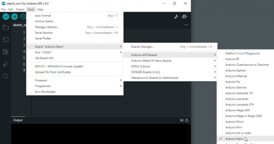
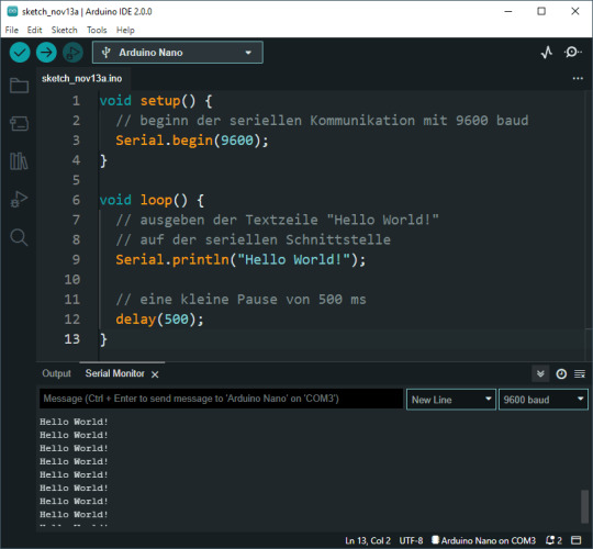
Auswählen des Mikrocontrollers Arduino Nano in der Arduino IDE "Hello World!" auf der seriellen Schnittstelle Starten möchte ich jedoch zunächst mit einem kleinen "Hello World!" Beispiel, in welchem wir Text auf der seriellen Schnittstelle ausgeben. Diesen Text können wir uns in der Arduino IDE anzeigen lassen, aber auch andere Tools welche Daten von der seriellen Schnittstelle lesen können wie Putty, MobaXTerm können diese anzeigen. Der Vorteil bei der Arduino IDE ist jedoch, dass wir dafür kein extra Tool benötigen. void setup() { // beginn der seriellen Kommunikation mit 9600 baud Serial.begin(9600); } void loop() { // ausgeben der Textzeile "Hello World!" // auf der seriellen Schnittstelle Serial.println("Hello World!"); // eine kleine Pause von 500 ms delay(500); } Wenn das kleine Programm hochgeladen wurde, sehen wir in der Konsole folgende Ausgabe. Aus diesem Text können wir entnehmen, wie viel Speicher von unserem Programm belegt wird und wie viel noch frei ist. Der Sketch verwendet 1634 Bytes (5%) des Programmspeicherplatzes. Das Maximum sind 30720 Bytes. Globale Variablen verwenden 200 Bytes (9%) des dynamischen Speichers, 1848 Bytes für lokale Variablen verbleiben. Das Maximum sind 2048 Bytes. Ausgabe der Textzeile "Hello World!" im seriellen Monitor der Arduino IDE.
Blinken der onboard SMD LED Die kleine SMD onboard LED kannst du über den digitalen Pin D13 oder der Konstante LED ansteuern. // onboard LED am digitalen Pin D13 angeschlossen // ansteuern über die Pin Nummer // #define led 13 // int led = 13; // ansteuern über einer Konstanten #define led LED_BUILTIN void setup() { // Definieren das der Pin der LED als // Ausgang dient. pinMode(led, OUTPUT); } void loop() { // Pin der LED auf HIGH setzen digitalWrite(led, HIGH); // eine kleine Pause von 500 ms. delay(500); // Pin der LED auf LOW setzen. digitalWrite(led, LOW); // eine kleine Pause von 500 ms. delay(500); } Wenn wir den Code nun auf den Mikrocontroller übertragen, dann blinkt die kleine, orange SMD LED auf der Platine im Intervall von 500 ms. Read the full article
0 notes

Text
v2.x.x. is the worst thing they couldve done to the arduino ide
not only did it fuck up my code back when it first updated like 6m ago, but im now finding out they changed the serial plotter to only show 50 points!?
i need to make graphs from the serial output and i need them yesterday, i tried 3rd party programs and not a single one worked cause theyre all in java or python or some such shit
ill have to roll back tmrw and deal w whatever shit that unleashes, fmsbl i do not have time for this i lost the whole day to this
1 note
·
View note
Text
How to build #DIY pen plotter ? Check out this 😍excellent project by #maker Szymon Kaliski 👏👍
#Arduino #Electronics #Tech #3dprinted #code #Hardware
Learn More - https://tinyurl.com/2c7h8uc3
0 notes
Link
Hello to Everyone,
I want to do a pen plotter. There are many plotter systems. I am doing it, the system that uses the belt.
GRBL and Arduino CNC Machine Working Principle Overview
https://youtu.be/Jyl_zIqxSdI
#Drawing Plotter#Arduino Plotter#Pen Plotter#CNC Plotter#DIY Plotter#Homemade Plotter#GRBL Plotter#Gcode plotter
0 notes
Video
instagram
Posted @withregram • @makerwizard Amazing project! What do you think about this project?😎🤔 u/_targz_ #plotter #arduino #raspberrypi #diy #diyelectronics #pcb #iot #led #science #atmel #atmel #esp8266 #soldering #stepper #pcbprototype #pcbdesign #servo #3dprinted #3dprinting #art #satisfyingvideos #satisfying (at Busan, South Korea) https://www.instagram.com/p/CFzcdAJj3hu/?igshid=3dmahsu4xyoi
#plotter#arduino#raspberrypi#diy#diyelectronics#pcb#iot#led#science#atmel#esp8266#soldering#stepper#pcbprototype#pcbdesign#servo#3dprinted#3dprinting#art#satisfyingvideos#satisfying
1 note
·
View note
Text
While browsing in a thrift store some months ago, I found a selection of stepper motors. I picked up some matching NEMA 17 motors, the size you find in 3d printers, but also two NEMA 08s.

The 08 refers to the size. NEMA specifies the size numbers as the size of the faceplate (around the motor's shaft), measured in tenths of an inch. So a NEMA 08 motor's face is 0.8" across — nicely compact, and I plan to make a little pen plotter with these.
The trouble starts when you try to make them run. These aren't "hobby motors", where if you stick one wire on either end of a battery, it runs. Stepper motors have, at minimum, four wires, so that's not going to work. You can look at a good description of how they work on Wikipedia, but suffice it to say that the easiest way to get real control on these is to use a microcontroller and a motor driver board. The microcontroller is a tiny computer that tells the motor driver how and when to move the motor, and the driver translates that into the proper voltages on the right wires.
Fortunately, I have both of these. For a microcontroller, I have an Arduino — just an old one I had lying around, which is plenty — and for a motor driver, I have a Seeedstudio Motor Shield, which plugs into the Arduino and provides places to connect the stepper motor and the power to drive it (I got these at Radio Shack, which may indicate just how long I've had them). Unfortunately, a Motor Shield can only drive a single stepper, and I want to drive both of them. I could buy a driver board to run both motors, but I don't really want to spend extra money right now. I do have a second Motor Shield, so the quickest thing would be to use two Arduinos, put a Motor Shield on each one, and have the two microcontrollers coordinate somehow. But that's much more complicated than running both motors off one micro.

What I arrived at is the above. A Motor Shield uses pins 8, 11, 12, and 13 to drive the motor. But each Motor Shield also has what Seeed calls Grove connectors along the side, which let you get to the pins on the Arduino that the shield isn't using. So I've wired some of those to the operative pins on the second shield. So when the standard setup to use a Motor Shield goes like:
StepperMotor myStepper(stepsInARevolution, 8, 11, 12, 13);
I can turn around and say:
StepperMotor myStepper1(stepsInARevolution, 8, 11, 12, 13);
StepperMotor myStepper2(stepsInARevolution, 2, 3, 4, 5);
and behave as though I had a shield that could run both at once.
4 notes
·
View notes
Video
youtube
Man I really want a pen plotter now.
#Look how fast that thing was#pen plotter#I feel like you must be able to make something equivalent for cheap.#Like something arduino based.
2 notes
·
View notes
Text
Two Arduinos are used to control this DIY three-axis CNC plottee
We’ve seen a number of homemade CNC machines throughout the years, but Tuenhidiy’s build — made from some discarded materials — is no less impressive. This unique CNC plotter features a frame cleverly constructed out of two wooden wine boxes, which appear to be the perfect size with space for an Y-axis bed and an upright structure that actuates X movements. For the Z component, a pen is lifted using parts from a recycled CD player drive.
Electronics-wise, the project is also quite interesting as it employs servos rather than steppers for its X and Y axes. Actuation is handled by an Arduino Uno with pre-installed GRBL firmware and a CNC shield, which sends commands to an Arduino Mega running custom firmware. The Mega — plus a custom adapter board and an L293D shield — takes care of PID control for the motors.
More details on the machine can be found in Tuenhidiy’s write-up, and you can see it demonstrated in the video below.
youtube
youtube
The post Two Arduinos are used to control this DIY three-axis CNC plottee appeared first on Arduino Blog.
Two Arduinos are used to control this DIY three-axis CNC plottee was originally published on PlanetArduino
1 note
·
View note
Text
Online Electronics Store In Pakistan
Rawlix is the biggest online shopping store for electronics in Pakistan which serves the best quality of electronic supplies in all over Pakistan. Rawlix.com first made waves in Pakistan’s electronics e-commerce market after its introduction in 2011. Since then we have become Pakistan's largest electronics platform for online shopping with a network spread across Pakistan. Our vision is to make available all electronics products at hall road Lahore online through our platform to our customers across all over Pakistan. Rawlix prides itself on not being just another e-e-commerce venture in Pakistan. Our team works tirelessly to make sure that we serve users with a great online shopping experience and value for their purchases. Whether you shop online through our website or our physical store Technique Centre located in Lahore, you can expect easy navigation, customized recommendations, and a great online shopping experience guaranteed.
What Makes Us Different from Other Online Shopping Platforms?
Select from the Biggest Online Marketplace in Pakistan with over 5 thousand products to select from, Rawlix offers its customers the most comprehensive listing of electronic products in the all over Pakistan. Whether you’re looking for Arduino components, electronic appliances, lab equipment, digital and analog meters there is something for everyone.
Hassle Free Delivery
Online shopping is only as good as its execution and Rawlix promises hassle-free delivery from the time you order your package dropped from your home. We deliver in both major and smaller cities alike and give you the choice to track your parcel as it makes its way to you so you always know your order status. If you are unsatisfied with any aspect of your order, we have a simple 9-day return or exchange policy.
Shop with verified vendors
Rawlix believes that online shopping in Pakistan has its fair share of risks. This is why Rawlix Marketplace has the security of choosing from verified vendors and brands from Karachi, Lahore, Islamabad, and all over Pakistan. Now you’ll never have to second guess authenticity because Rawlix makes sure to do it for you!
Buy Value, not Just Goods with Rawlix
Rawlix not only complements online shopping in Pakistan but also aims to make it easier for you to give back to society. With charities spread across the fields of education, healthcare, environmental protection, and shelter, you can choose to make a big difference with just a few simple clicks.
Rawlix is a number one source for electronics products and items where you should buy everything related to Electronics like Stepper Motor, CNC, 3D-Printers, Arduino, Addressable Led Strip, Raspberry Pi, Power Supply and other electronic components. Rawlix also deals in a wide range of tools like Soldering Tools, Power Tools, Hardware Tools and Toolbox. Rawlix also have a huge variety of Meters like Energy Meter, Multimeter, Clamp meter and Analog Meter. We're dedicated to giving you the very best of electronics products, with a focus on premium quality, appropriate prices, and fast delivery. Rawlix Team also help students in university projects also in a professional carrier.
Rawlix is the largest manufacturer of CNC, 3D Printer, 3D Plotter, and Drones in all over Pakistan. We also deals in CNC and 3D printer equipment’s like Vexta Stepping Motor, Nema 17 Stepper Motor, Nema 23 Stepper Motor, Coupling, Ball Beating, Smooth Rod, Linear Guide, Carbide Steel PCB Drill Bit, Lead Screw, Aluminium Profile, GT2 Pulley, Timing Belts, Timing Pulley and Ball Screw in all over Pakistan.
History of Beginning
Established by the Technique Centre in 1995. It has come a long way from its origin and gets to be Rawlix in 2020. Their enthusiasm for serving technology led them to do plenty of research when Rawlix first began, so that Rawlix can serve all the electronics in one place.
We now represent customers all over Pakistan and are delighted that we will transform our enthusiasm into our website. We hope you continue to enjoy our services as much as we like selling them to you. Please don't hesitate to contact us, if you have any questions or suggestions.
1 note
·
View note
Text
AZ-Envy - auslesen der Sensordaten

In diesem Beitrag möchte ich dir zeigen, wie du die Sensordaten des AZ-Envy auslesen kannst.

Den AZ-Envy habe ich dir bereits im Beitrag Vorstellung AZ-Envy vorgestellt und gezeigt, wie dieser angeschlossen und programmiert wird.
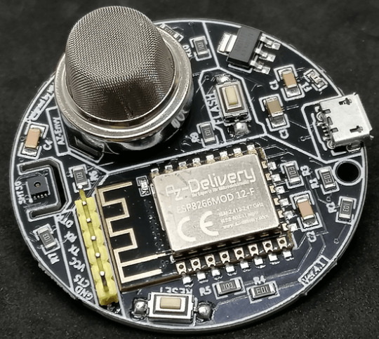
Auf dem AZ-Envy ist ein ESP8266 verbaut und zwei Sensoren. Der SHT30 Sensor dient für die Erfassung von Luftfeuchtigkeit und Temperatur sowie ein MQ-2 für Luftqualität.
Benötigte Ressourcen
Wenn du dieses Board wie nachfolgend programmieren und die Sensordaten vom AZ-Envy auslesen möchtest, dann benötigst du: - einen AZ-Envy, - ein Micro-USB Datenkabel, - ein FTDI232 Adapter, - ein Mini-USB Datenkabel, - drei Breadboardkabel, weiblich-weiblich, 10 cm
Anschluss des FTDI232 Adapters an den AZ-Envy
Der FTDI232 Adapter wird mit drei Breadboardkabel mit dem AZ-Envy verbunden. AZ-EnvyFTDI232 AdapterRXRXTXTXGNDGND Zusätzlich musst du das Board mit einem Micro-USB-Kabel verbinden, damit dieser Strom erhält.
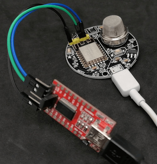
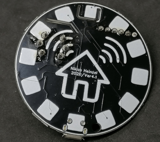
Board AZ-Envy mit FTDI232 Adapter
Probleme mit dem Sensor MQ-2 & SHT30
Der Luftqualitätssensor MQ-2 wird im Betrieb sehr warm und durch die ungünstige Platzierung zur Nähe des Sensors SHT30 erhältst du von letzterem ggf. sehr ungenaue Werte.

Temperatur des MQ-2 Sensors im Betrieb In einigen Foren wurde bereits darüber sehr ausgiebig diskutiert. Eine Lösung dazu ist den Sensor SHT30 abzuschirmen, in der Platine ist eine kleine Rinne eingelassen, in welche man ein Schild einlassen kann und somit zumindest etwas Wärme vom Sensor ableiten kann.
Programmieren in der Arduino IDE
Wie du den Mikrocontroller in der Arduino IDE einrichtest, habe ich dir bereits im oben verlinkten Beitrag gezeigt. Im nachfolgenden YouTube-Video zeige ich dir, wie du am AZ-Envy die Sensordaten auslesen kannst. https://youtu.be/E8-UMpHXCOw Bibliotheken für die verbauten Sensoren Für das Auslesen der Sensoren benötigen wir zwei Bibliotheken, diese können wir über die Shopseite von AZ-Delivery zum Board als ZIP-Datei herunterladen und über Sketch > Include Library > Add .ZIP Library in der Arduino IDE importieren. Auslesen der Luftfeuchtigkeit und Temperatur vom SHT30 Sensor Der Sensor SHT30 liefert wie erwähnt die Temperatur sowie die relative Luftfeuchtigkeit. Nachfolgend nun ein kleines Programm, welches diese Daten ausließt und auf der seriellen Schnittstelle ausgibt. //Bibliothek zum auslesen der Sensorwerte //vom SHT30 Sensor #include //instanziieren eines Objektes vom Typ SHT3X //mit der I2C Adresse 0x44 SHT3X sht30(0x44); void setup() { //beginn der seriellen Kommunikation mit 9600 baud Serial.begin(9600); } void loop() { //Wenn die kommunikation per I2C mit dem Sensor //erfolgreich war, dann... if (sht30.get() == 0) { //lesen der Temperatur in Grad Celsius float temperature = sht30.cTemp; //lesen der rel. Luftfeuchtigkeit in % float humidity = sht30.humidity; //ausgeben der Temperatur Serial.print("Temperatur: "); Serial.print(temperature); Serial.println("°C"); //ausgeben der rel. Luftfeuchtigkeit Serial.print("rel. Luftfeuchtigkeit: "); Serial.println(humidity); Serial.println("%"); } //eine kleine Pause von 5 Sekunden delay(5000); }

Auslesen der Luftqualität des MQ-2 Sensors Der Luftqualitätssensor MQ-2 wird im Betrieb warm und liefert je länger die Läuft genauere Messwerte, daher würde ich dir empfehlen diesen für min. 1h laufen zu lassen, bevor du die echten Werte verwenden kannst. //Luftqualitätssensor MQ-2 ist //am analogen Pin A0 angeschlossen #define MQ2Pin A0 void setup() { //beginn der seriellen Kommunikation mit 9600 baud Serial.begin(9600); //analogen Pin als Ausgang definieren pinMode(MQ2Pin, INPUT); } void loop() { //lesen des analogen Wertes int sensorValue = analogRead(MQ2Pin); //Ausgeben des gelesenen Wertes auf //der seriellen Schnittstelle Serial.print("Luftqualität: "); Serial.print(sensorValue); Serial.println("ppm"); //eine kleine Pause von 2 Sekunden delay(2000); }

Wert im seriellen Plotter der Arduino IDE visualisieren
Die Arduino IDE verfügt über einen seriellen Plotter, welchen wir nutzen können, um Sensorwerte in einem Liniendiagramm zu visualisieren.

Dazu müssen wir die Legende und die Werte in einem bestimmten Format auf der seriellen Schnittstelle ausgeben. #include SHT3X sht30(0x44); #define MQ2Pin A0 float temperature = 0; float humidity = 0; void setup() { Serial.begin(9600); pinMode(MQ2Pin, INPUT); } void loop() { if (sht30.get() == 0) { temperature = sht30.cTemp; humidity = sht30.humidity; } int sensorValue = analogRead(MQ2Pin); Serial.print("Temperatur(°C):"); Serial.print(String(temperature, 2)); Serial.print("t"); Serial.print("rel.Luftfeuchtigkeit(%):"); Serial.print(String(humidity, 2)); Serial.print("t"); Serial.print("Luftqualität(analog):"); Serial.print(String(sensorValue, DEC)); Serial.println(); delay(2000); }
Download der Programme
Hier nun die gezeigten Programme zum einfachen Download als ZIP-Datei für die Arduino IDE. AZ-Envy - auslesen der Sensordaten - SHT30Herunterladen AZ-Envy - auslesen des Luftqualitätssensors - MQ-2Herunterladen AZ-Envy - visualisieren der Sensordaten im seriellen Plotter der Arduino IDEHerunterladen Read the full article
0 notes

Text
DIY ECG Part 4
Part 1 Part 2 Part 3
Software
The last part of this tutorial is about the software needed to display the ECG signal on your computer. This guide is based on the tutorial found on Sparkfun (https://learn.sparkfun.com/tutorials/ad8232-heart-rate-monitor-hookup-guide/all). If you are stuck at some point in this tutorial, I would recommend you to read the section on Sparkfun, as their guide is more detailed.
Three pieces of software are needed:
Arduino IDE (https://www.arduino.cc/en/Main/Software)
Processing IDE (https://processing.org/download/)
the adapted code (https://mega.nz/#!9roDGAha!21aKPDvBIuEhjTG9IAFJlwZZrH9vBTv6E5AQN-6GP2g)
Install the version of the Arduino IDE and Processing IDE for your operating system. For the Arduino board to be recognized by Windows, one needs to install an additional driver. Refer to this site for the detailed installation instructions. I would also recommend you to get familiar with the interface and try to upload the first demo program as described under "Launch and Blink!" on the same page. Note: for Tools->Board you would choose "Arduino Nano", for Tools->Processor "ATmega 328p (old bootloader)" and for Tools->Port you would try out all options until it works!
If that worked, we can now upload the code for the ECG. Extract the zip archive with the code and open up "Heart_Rate_Display_Arduino.ino" in the "Heart_Rate_Display_Arduino" folder with the Arduino IDE. Make sure the options under Tools are set to the same values as before. Note: The port can change over time, especially if unplugging the Arduino at some time! The ECG can already be tested. Make sure, the ECG electrodes are placed correctly on your body (see last part 3 of this tutorial). Now open the Serial plotter under the Tools menu in the Arduino IDE. The "baud rate" should be set to the value 19200. This is the rate at which Arduino and computer communicate. If everything was done correctly, you should already see something very much like an ECG!
For a fancier output, open up the Processing IDE. Open the "Heart_Rate_Display_Processing.pde" file from the "Heart_Rate_Display_Processing" folder. For sound output (yes, the beeping of the ECG!) an extra programming library is needed. Go to Tools->Add Tool and there to the Libraries tab. Search for "minim" and click on the Install button on the lower left corner of the window. After it is installed, close the window. Then run the code by pressing the Play button in the main window. Probably it will crash on the first try. Increment the zero found in the code at the line with "myPort = new Serial(this, Serial.list()[0], 19200);" and try again. By doing so, one searches for the Arduino as before in the Arduino IDE. Repeat the process until it works. The correct number should be probably under 10.
If you did everything correctly, the output should look somewhat like this:
vimeo
I wish you a lot of fun with your DIY ECG monitor!
13 notes
·
View notes
Link
Pen Plotter CNC Plotter Arduino
https://youtu.be/Jyl_zIqxSdI
https://roboticcode2020.blogspot.com/2021/02/drawing-plotter.html
#Drawing Plotter#Arduino Plotter#Pen Plotter#CNC Plotter#DIY Plotter#Homemade Plotter#GRBL Plotter#Gcode plotter
0 notes
Video
instagram
Looking to make your own CNC Machine? @tech_boys_toys has got you covered! - He used a small ACP sheet, wood or acrylic for the base and plotter bed. - For the X and Y axis he used two stepper motors and rails from DVD-CD drives, and for the Z axis he used a small servo motor. - The Arduino-based circuit is using the ATmega328 microcontroller and two L293 motor driver ICs. - DM for a link to the full video and tag someone who would like to build this! - - #arduino #cncmachining #dvdplayer #cdplayer #servo #acrylic #electronics #diyelectronics #stem #stemeducation #hobbylobby #maker #makersgonnamake #elementaryteacher #atmega #arduinoproject #engineering #drawingmachine #writingmachine #microcontroller #diyprojects #youtubechannel (at Busan, South Korea) https://www.instagram.com/p/B5ltkcPl3yq/?igshid=sue5e2qlq4ca
#arduino#cncmachining#dvdplayer#cdplayer#servo#acrylic#electronics#diyelectronics#stem#stemeducation#hobbylobby#maker#makersgonnamake#elementaryteacher#atmega#arduinoproject#engineering#drawingmachine#writingmachine#microcontroller#diyprojects#youtubechannel
2 notes
·
View notes
Text

Artist Statement
‘Mutate’ is a dynamic installation which reacts to the user’s kinetic energy (input) and translates this raw data to produce the movement of an XY plotter (process) which creates an interactive display of articulate and engaged motions, presented through a magnetic ferrofluid (output). We often see ourselves through mirrors, photos, and reflective surfaces, but something that we tend to overlook is the physical representation of ourselves through movement and energy. Everyone’s kinetic energy is different, and that is what ‘Mutate’ aims to portray.
The use of a magnetic substance is also an enigmatic concept, as the earth’s core contains a geomagnetic field that extends from the earth’s interior out into space. For the user to be able to control such a cryptic substance through their own kinetic energy is a complex experience made possible through ‘Mutate’. The design is produced through Arduino software, which uses Grbl and Gcode to control the movement of an XY plotter. An augmented visualisation is created through the input of kinetic energy, which is captured through a PIR motion sensor and allows for the mutation and movement of a magnetic ferrofluid - encased within an acrylic tank.
2 notes
·
View notes