#Arduino and Relay
Explore tagged Tumblr posts
Visit Tumblr Blog
Explore Tumblr blogs with no restrictions, modern design and the best experience.
Last Seen Tumblr Blogs


Fun Fact
The average Tumblr user visits about 67 pages every month.
Text
Arduino und DS3231: Relais jeden Tag automatisch zur gleichen Uhrzeit schalten

In meinem bereits veröffentlichten Beitrag Zeitgesteuerte Schaltung mit Arduino: Programmieren von RTC, LCD und Relaismodul habe ich dir erläutert, wie man ein Relais via Zeitstempel aktivieren / deaktivieren kann. Dieser kleine Beitrag soll den Beitrag ergänzen und aufzeigen, wie man einen täglichen Timer erstellen kann, um automatisch jeden Tag zur gleichen Uhrzeit ein Relais zu aktivieren oder zu deaktivieren. https://youtu.be/FjLisNBPAV0 Diese Schaltung kannst du zum Beispiel auch nutzen, um deine Weihnachtsbaumbeleuchtung zu schalten.
Rückblick - Relais & RTC DS3231 am Arduino UNO R3
Schauen wir uns kurz noch einmal die Schaltung am Arduino UNO R3 an:
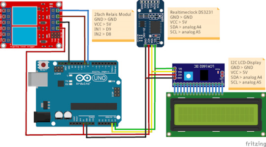
zeitgesteuerte Schaltung mit dem Arduino UNO R3, RTC und LCD-Display Für den Aufbau der Schaltung habe ich nachfolgende Bauteile verwendet: - einen Arduino Nano V3* - ein USB-Datenkabel* - eine RTC DS3231* - ein I2C LCD-Display* - ein Relais Shield* - diverse Breadboardkabel*, - ein 400 Pin Breadboard*
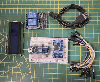
Arduino Nano V3, Relais Modul und RTC DS3231 sowie LC-Display Hinweis von mir: Die mit einem Sternchen (*) markierten Links sind Affiliate-Links. Wenn du über diese Links einkaufst, erhalte ich eine kleine Provision, die dazu beiträgt, diesen Blog zu unterstützen. Der Preis für dich bleibt dabei unverändert. Vielen Dank für deine Unterstützung!
Programm zum automatischen Schalten eines Relais zur gleichen Uhrzeit
Als Basis für dieses kleine Projekt verwende ich den bereits veröffentlichen Code zum Steuern eines Relais zu einem Zeitpunkt aus Datum und Uhrzeit. Diesen Code werden wir nun anpassen, um zu einer bestimmten Uhrzeit das Relais zu schalten. Klingt easy, ist es auch, wie du gleich sehen wirst. Programm: Zeitgesteuerte Schaltung mit RTC & Relaismodul für die tägliche SchaltungHerunterladen Im struct wo wir die Zeitpunkte zum Schalten der Relais definieren, kürzen wir das Datum hinaus. Relais relais1 = { 9, "Relais #1", { "", "14:22:00" }, { "", "14:22:10" } }; Relais relais2 = { 8, "Relais #2", { "", "14:22:05" }, { "", "14:22:15" } }; Die Funktion zum Prüfen der Zeitpunkte passen wir an und entfernen in den if-Bedingungen die Prüfungen auf das Datum. void checkCurrentTimestamp(Relais relais, Zeitstempel zeitstempel) { if (zeitstempel.zeit == relais.actionON.zeit) { Serial.println("aktivieren"); digitalWrite(relais.digitalPin, LOW); } else if (zeitstempel.zeit == relais.actionOFF.zeit) { Serial.println("deaktivieren"); digitalWrite(relais.digitalPin, HIGH); } } Das komplette Programm: //Bibliothek zum ansteuern des LCD-Display via I2C #include //Bibliothek für die kommunikation mit der RTC #include //Bibliothek zum kommunizieren mit dem //Bluetooth Modul über SoftwareSerial #include // I2C Adresse des RTC DS3231 #define RTC_I2C_ADDRESS 0x68 struct Zeitstempel { String datum; String zeit; }; struct Relais { int digitalPin; String desc; Zeitstempel actionON; Zeitstempel actionOFF; }; //Das Display wird über //die I2C Adresse 0x27 angesteuert //es hat 20 Zeichen pro Zeile //es hat 2 Zeilen LiquidCrystal_I2C lcd(0x27, 20, 2); char linebuf = {}; bool readData = false; Relais relais1 = { 9, "Relais #1", { "", "14:22:00" }, { "", "14:22:10" } }; Relais relais2 = { 8, "Relais #2", { "", "14:22:05" }, { "", "14:22:15" } }; // RX, TX SoftwareSerial btSerial(7, 6); void setup() { Serial.begin(9600); btSerial.begin(9600); //initialisieren des Displays lcd.init(); //aktivieren der Hintergrundbeleuchtung lcd.backlight(); pinMode(relais1.digitalPin, OUTPUT); pinMode(relais2.digitalPin, OUTPUT); digitalWrite(relais1.digitalPin, HIGH); digitalWrite(relais2.digitalPin, HIGH); } void loop() { readDataFromSerial(); if (readData) { String timestamp = linebuf; //Das Datum muss inkl. den Punkten 10 Zeichen lang sein String datum = timestamp.substring(0, 10); String tag = datum.substring(0, 2); String monat = datum.substring(3, 5); String jahr = datum.substring(6, 10); //Die Uhrzeit beginnt ab dem 11 Zeichen aus dem Zeitstempel String uhrzeit = timestamp.substring(11); String stunde = uhrzeit.substring(0, 2); String minute = uhrzeit.substring(3, 5); String sekunde = uhrzeit.substring(6); rtcWriteTimestamp(stunde.toInt(), minute.toInt(), stunde.toInt(), tag.toInt(), monat.toInt(), jahr.toInt()); } //bleibt leer Zeitstempel zeitstempel = readRtc(); lcd.setCursor(0, 0); lcd.print(zeitstempel.datum); lcd.setCursor(0, 1); lcd.print(zeitstempel.zeit); checkCurrentTimestamp(relais1, zeitstempel); checkCurrentTimestamp(relais2, zeitstempel); delay(500); } void checkCurrentTimestamp(Relais relais, Zeitstempel zeitstempel) { if (zeitstempel.zeit == relais.actionON.zeit) { Serial.println("aktivieren"); digitalWrite(relais.digitalPin, LOW); } else if (zeitstempel.zeit == relais.actionOFF.zeit) { Serial.println("deaktivieren"); digitalWrite(relais.digitalPin, HIGH); } } void readDataFromSerial() { //Zähler für die Zeichen byte counter = 0; readData = false; //Wenn Daten verfügbar sind dann... if (btSerial.available() > 0) { delay(250); readData = true; //solange Daten von der seriellen Schnittstelle //empfangen werden... while (btSerial.available()) { //speichern der Zeichen in dem Char Array char c = btSerial.read(); if (c != 'n') { linebuf = c; if (counter counter++; } } } Serial.println(linebuf); } } void rtcWriteTimestamp(int stunde, int minute, int sekunde, int tag, int monat, int jahr) { Wire.beginTransmission(RTC_I2C_ADDRESS); Wire.write(0); // Der Wert 0 aktiviert das RTC Modul. Wire.write(decToBcd(sekunde)); Wire.write(decToBcd(minute)); Wire.write(decToBcd(stunde)); Wire.write(decToBcd(0)); // Wochentag unberücksichtigt Wire.write(decToBcd(tag)); Wire.write(decToBcd(monat)); Wire.write(decToBcd(jahr - 2000)); Wire.endTransmission(); } //auslesen der Daten von der RealtimeClock Zeitstempel readRtc() { //Aufbau der Verbindung zur Adresse 0x68 Wire.beginTransmission(RTC_I2C_ADDRESS); Wire.write(0); Wire.endTransmission(); Wire.requestFrom(RTC_I2C_ADDRESS, 7); int sekunde = bcdToDec(Wire.read() & 0x7f); int minute = bcdToDec(Wire.read()); int stunde = bcdToDec(Wire.read() & 0x3f); int wochentag = bcdToDec(Wire.read()); int tag = bcdToDec(Wire.read()); int monat = bcdToDec(Wire.read()); int jahr = bcdToDec(Wire.read()) + 2000; char datum; sprintf(datum, "d.d.", tag, monat, jahr); char zeit; sprintf(zeit, "d:d:d", stunde, minute, sekunde); return { datum, zeit }; } //Convertiert Dezimalzeichen //in binäre Zeichen. byte decToBcd(byte val) { return ((val / 10 * 16) + (val % 10)); } //Convertiert binäre Zeichen in Dezimal //Zeichen. byte bcdToDec(byte val) { return ((val / 16 * 10) + (val % 16)); } Read the full article
0 notes
Text
Electronic Component UAE

Next Power Groups of company, established in 2012 is a leading high service provider Electronics, Electronic Components & Industrial Automation Spare Parts in Dubai-UAE, OMAN and establishing their branches around the GCC.
They are the Manufacturer / Exporters / Service Providers / Suppliers Of IGBT Modules, Stud Thyristors, Diode Modules, Electronic Component Tester, IC Programming System, AC to DC Converter, DC To DC Converter, Limit switch, Electronic Transformer, Power Supply, Ultra cell Battery, Voltage Potentiometer, Stepper Motor, DC Motor, Arduino Starter Kit, Servo Motor, Arduino Uno, Ultrasonic Sensor, Humidity Sensor Module, IR Sensor set, Switches and indicators, Relay, Timer, Relay Sockets, IGBT, Fuse, Fan, Contactors, Breakers etc.
Distributor of electronic, electrical, components, industrial and maintenance, repair & operations (MRO) products – with fast, easy access to over 40,000 stocked products, 24 hours a day, 365 days a year,
Products : Switches, Power Supply, Modules, IC, Diodes, Capacitors, Resistors, indicators, Sensors, Cables, Connectors, SSR, Arduino, Potentiometer, Motors, Relays, Timers, Relay Sockets, IGBT, Fuse, Fan, Contactors, Breakers, Transformers etc.
We supply these electric products to more suppliers in UAE, We have a wide variety of branded products. MEANWELL, AUTONICS, FOTEK, AURDUINO, BOURNS, BUSSMANN, SCHNEIDER ELECTRIC, SIBA, ABB, LONG BATTERY, SUNON FAN, EBM PAPST FAN, CRYDOM, FLUKE, FUJI ELECTRIC, IDEC, EATON, FOTEK, INFINEON, INTERNATIONAL RECTIFIERS, LONG BATTERY, POWER PLUS, SIEMENS, LS ELECTRIC, GENERAL ELECTRIC, FINDER, IXYS, MITSUBISHI, OMRON, PEAK ELECTRONIC, POWEREX, SANREX, SCHRACK, SEMIKRON, XELTEK Etc.
Please send your inquiry to this email
Website : Oncomponents Online electronicstore
[email protected] | For Order �� +971-567131624
#electronic components#electronics#power supplies#arduino#modules#capacitors#relays#resistor#mean well
1 note
·
View note
Video
youtube
DIY Temperature Controller for Molding Systems | Arduino Tutorial
#youtube#DIY#Arduino Tutorial#Temperature Controller#Molding Systems#Injection Molding#Arduino Nano#Membrane Keypad#LCD#Relay Module#Max6675 Module#Thermocouple#Plastic Molding#Electronics Tutorial#Maker Community#Plastic Injection Molding#Arduino#Hot Nozzle#Molding Process#MAX6675#LCD Display
1 note
·
View note
Text
All electronic components are buy at reasonable price in sensorembedded.com
#arduino#sensors#motors#shield#wifi#relay#cables#rfid#interfacing#drones#ebike#tools#electronic components
0 notes
Photo

Single Relay Timer (Arduino 1 Channel Relay) https://shores.dev/arduino-single-channel-relay-timer/?utm_source=tumblr&utm_medium=social&utm_campaign=ReviveOldPost
0 notes
Text
Top 10 Projects for BE Electrical Engineering Students
Embarking on a Bachelor of Engineering (BE) in Electrical Engineering opens up a world of innovation and creativity. One of the best ways to apply theoretical knowledge is through practical projects that not only enhance your skills but also boost your resume. Here are the top 10 projects for BE Electrical Engineering students, designed to challenge you and showcase your talents.
1. Smart Home Automation System
Overview: Develop a system that allows users to control home appliances remotely using a smartphone app or voice commands.
Key Components:
Microcontroller (Arduino or Raspberry Pi)
Wi-Fi or Bluetooth module
Sensors (temperature, motion, light)
Learning Outcome: Understand IoT concepts and the integration of hardware and software.
2. Solar Power Generation System
Overview: Create a solar panel system that converts sunlight into electricity, suitable for powering small devices or homes.
Key Components:
Solar panels
Charge controller
Inverter
Battery storage
Learning Outcome: Gain insights into renewable energy sources and energy conversion.
3. Automated Irrigation System
Overview: Design a system that automates the watering of plants based on soil moisture levels.
Key Components:
Soil moisture sensor
Water pump
Microcontroller
Relay module
Learning Outcome: Learn about sensor integration and automation in agriculture.
4. Electric Vehicle Charging Station
Overview: Build a prototype for an electric vehicle (EV) charging station that monitors and controls charging processes.
Key Components:
Power electronics (rectifier, inverter)
Microcontroller
LCD display
Safety features (fuses, circuit breakers)
Learning Outcome: Explore the fundamentals of electric vehicles and charging technologies.
5. Gesture-Controlled Robot
Overview: Develop a robot that can be controlled using hand gestures via sensors or cameras.
Key Components:
Microcontroller (Arduino)
Motors and wheels
Ultrasonic or infrared sensors
Gesture recognition module
Learning Outcome: Understand robotics, programming, and sensor technologies.
6. Power Factor Correction System
Overview: Create a system that improves the power factor in electrical circuits to enhance efficiency.
Key Components:
Capacitors
Microcontroller
Current and voltage sensors
Relay for switching
Learning Outcome: Learn about power quality and its importance in electrical systems.
7. Wireless Power Transmission
Overview: Experiment with transmitting power wirelessly over short distances.
Key Components:
Resonant inductive coupling setup
Power source
Load (LED, small motor)
Learning Outcome: Explore concepts of electromagnetic fields and energy transfer.
8. Voice-Controlled Home Assistant
Overview: Build a home assistant that can respond to voice commands to control devices or provide information.
Key Components:
Microcontroller (Raspberry Pi preferred)
Voice recognition module
Wi-Fi module
Connected devices (lights, speakers)
Learning Outcome: Gain experience in natural language processing and AI integration.
9. Traffic Light Control System Using Microcontroller
Overview: Design a smart traffic light system that optimizes traffic flow based on real-time data.
Key Components:
Microcontroller (Arduino)
LED lights
Sensors (for vehicle detection)
Timer module
Learning Outcome: Understand traffic management systems and embedded programming.
10. Data Acquisition System
Overview: Develop a system that collects and analyzes data from various sensors (temperature, humidity, etc.).
Key Components:
Microcontroller (Arduino or Raspberry Pi)
Multiple sensors
Data logging software
Display (LCD or web interface)
Learning Outcome: Learn about data collection, processing, and analysis.
Conclusion
Engaging in these projects not only enhances your practical skills but also reinforces your theoretical knowledge. Whether you aim to develop sustainable technologies, innovate in robotics, or contribute to smart cities, these projects can serve as stepping stones in your journey as an electrical engineer. Choose a project that aligns with your interests, and don’t hesitate to seek guidance from your professors and peers. Happy engineering!
5 notes
·
View notes
Text
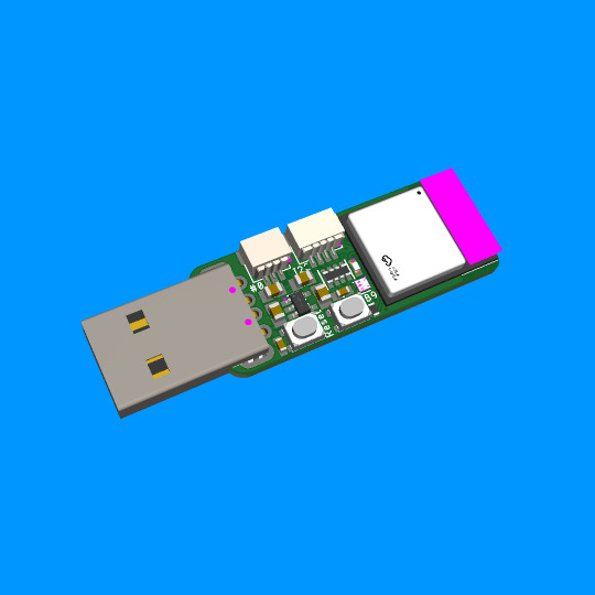
ESP32-C6 Trinkey is a USB Key with Wi-Fi/BLE/ZigBee 🔑🌐🔧
Having wrapped the feather ESP32-C6 (https://github.com/espressif/arduino-esp32/pull/9961) we think it would be neat to have a USB key 'Trinkey' board for the 'C6 because with WiFi+BLE+ZigBee and USB support, this could act as a low-cost gateway or relay board. We kept it simple here: USB type A in, two buttons for resetting and bootloader-select or user input, one red LED, one NeoPixel, Qwiic/Stemma QT I2C port, and a 3-pin JST SH with gpio #0, which can do PWM/ADC/digital in case you want to add another potentiometer, relay, servo or NeoPixels (on the back you can select if you wish to 3V or 5V power). The goal here is to keep it small, cheap, and extensible. We think we did a good job; what do you think?
#adafruit#esp32#arduino#trinkey#usbkey#gateway#relayboard#iot#smarttech#diyproject#microcontroller#pwm#zigbee
6 notes
·
View notes
Text
13. April 2024
Die smarte Jalousie
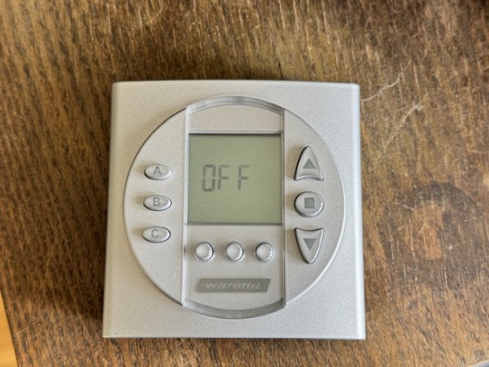
Wir haben eine elektrische Jalousie. Die hält im Sommer die Sonnenwärme draußen und im Winter hat man etwas Sichtschutz und so. Dazu gibt es eine Fernbedienung. Damit ist es leicht, die Jalousie rauf- und runterfahren zu lassen. Weil wir vor ein paar Jahren, als die ganze Technik installiert wurde, auch etwas automatische Steuerung haben wollten, gab es seinerzeit auch eine Schaltuhr dazu.
Ich behaupte, dass ich mich eigentlich nicht besonders dumm anstelle, wenn es darum geht, so eine Schaltuhr zu programmieren. Aber dieses Gerät ist eine einzige Katastrophe. Bis heute ist es mir nicht gelungen, die so zu programmieren, dass die Jalousie dann herauf- und hinunterfährt, wenn sie soll. Zwar meistens, aber nicht zufriedenstellend. Wenn sie einmal funktionierte: Bloß nicht mehr anrühren, bis der Übergang von Sommer zu Winter und umgekehrt Maßnahmen verlangten. Das ist der Übeltäter, hier inzwischen inaktiv:
Zwischenzeitlich übernimmt Apple Homekit einige Funktionen in unserem Haus, z. B. die Steuerung der Warmwasserpumpe. Und da dachte ich, dass ich die Jalousie dort auch andocken könnte. Geht ja auch mit Funk und so. Aber leider ist es etwas undurchschaubar, was man nun für Gerätschaften braucht. Der Hersteller scheint nicht nur bei seinen Bedienungsanleitungen zur Verwirrung zu neigen. Ich bin mir also nicht sicher, ob die Steuerung überhaupt mit Apple Homekit gehen würde.
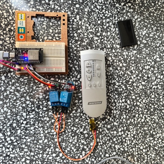
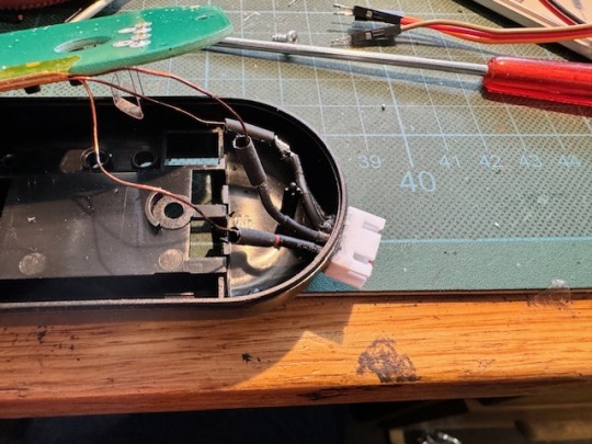
Also suche ich im Internet nach anderen Lösungen. Ein bisschen kann ich mit Arduinos umgehen, und so finde ich eine Lösung, wie man ein ESP32-Board mit Apple Homekit verheiraten kann. Meine Idee: Ich schalte mit dem ESP32 ein paar Optokoppler oder Relais, die so tun, als ob sie die Knöpfe an der Fernbedienung meiner Jalousie drücken. Dafür muss ich allerdings erst mal ziemlich filigrane Drähtchen an den richtigen Stellen der Platine anlöte. Diese Kontakte sind mit den Tastern auf der Platine verbunden.

Die Kupferlackdrähte enden dann an zwei Relais am ESP32-Board. Ich stecke das erst mal alles auf einer Steckplatine zusammen. Es funktioniert. Gegen Optokoppler entscheide ich mich, weil vermutlich die zu schaltende Spannung zu gering ist.
Meistens jedenfalls. Denn immer wieder verliert das ESP32-Board die Verbindung zum Homekit-Netzwerk. Auch hier ergoogle ich mir eine Lösung. Die besteht offenbar darin, dem WiFi-Router einen festen Kanal zuzuweisen. Ich hoffe, dass damit auch dasselbe Problem mit anderen Geräten passé ist, die sich ebenfalls immer mal wieder aus dem Verbund verabschieden.
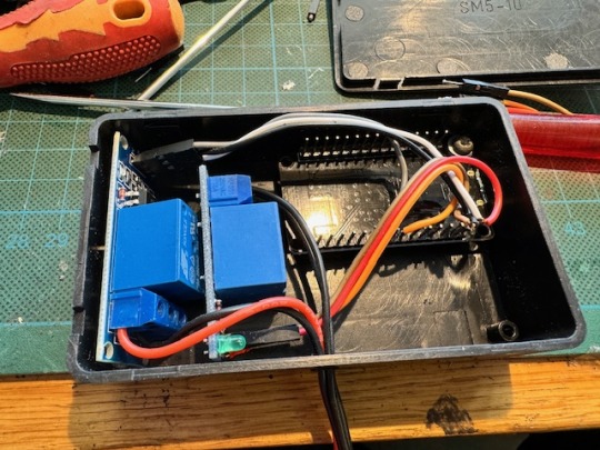
Damit das alles besser nutzbar wird, kommt in die Fernbedienung der Jalousie eine Anschlussbuchse und das ESP32-Board mit den Relais in eine kleine Box, aus der das passende Verbindungskabel herausguckt.
Auf den Platinen der Relais befanden sich noch LEDs. Die habe ich aus Stromspargründen entfernt. Man sieht davon ja eh nichts.
Man kann nun die Knöpfe der alte Fernbedienung nach wie vor manuell bedienen, aber die Jalousien auch von der Home-App aus ereignis- oder zeitgesteuert herauf- und hinunter fahren lassen.

(Markus Winninghoff)
5 notes
·
View notes
Text
A two-channel relay module featuring 2x Omron G3MB-202P solid state relays. This 5V 2-Channel SSR Solid State Relay Module 240V 2A Output with Resistive Fuse is capable of switching AC voltages between 100 and 240V at up to a 2A current. The module can be controlled from a 5V digital source such as an Arduino microcontroller.
This is a 2 Channel SSR relay module, each relay channel has 3 separate terminals, NO (Normal Open), COM (Common), NC (Normal Closed). When the input logic voltage is applied to the coil, the NC will disconnect from the COM breaking the conductivity between the two. At the same time, the NO will connect with the COM allowing conductivity between them. Depending on your wiring this will turn on or off the connected load.
3 notes
·
View notes
Text
Terry and Julia Group Project 1
Video Walkthrough LinkImage of the Project
The last two weeks Terry and I worked on our project called “Hit the Dick” (see video walkthrough above).
Aim of the Game:Each player has one strap-on game controller containing an Airpump, a rgb-LED, as well as a capacitive touch sensor attached to the tip. The game starts by randomly choosing one player whose strap-on will light up green after a random delay. That player has to hit the other players strap on within 3 seconds. If the player succeeds in hitting it before the opponent has dodged, the players starp-on will fill with a little bit of air. Players then take turn until one of the players has gained 5 points.
Hardware:LED: serves to indicate the current state of the game: Who is hitting, who has to dodge. AirPump that fills Silicone strap-on with air: Serves as a funny way to indicate the players points. The higher the Point count, the “higher” the strap-on will be (lol).Capacitive Touch Sensor: detects the slapping
Process:Terry and I ran into a few difficulties during building this project: Here are some interesting findings summed up:
Building the silicone strap-ons: It was really challenging to create 3D printed negatives that would serve as the mold for the strap-ons because we needed to make sure we had enough hallow space for the air to fill.
Getting the Airpumps to work: After some testing, we realized that the Arduino does not have enough power to power the Airpumps using the GPIO pins. Hence, we ended up using a Relay connected to an external 5V 2A power source!
3 notes
·
View notes
Text
Buying Electronic Components Online in India — What to Keep in Mind
Electronics is a field where small parts make a big difference. If you're building something — a simple sensor circuit, maybe a GSM tracker, or even just testing modules — sourcing the right components is half the work.
Going shop to shop looking for capacitors, ICs, or GPRS modules can be draining. Not to mention, stock may not be available, or the part isn’t original. That’s where online sellers come in.

Why Online Works Better (Most of the Time)
Instead of wasting hours traveling or calling five vendors, it’s easier to go online and search the part directly. You get to check datasheets, ratings, specs, pricing — all at once. It’s a better way to find both common and rare components.
In India, the trend is clear: more developers, students, and even R&D engineers now prefer to buy electronic components online. It's faster and often cheaper, too.
Looking for Specific Parts Like GPRS Modules?
Not every local store stocks communication modules. A GPRS module is commonly used in IoT, vehicle tracking, or remote data transmission projects. Online, you can compare multiple options, check if it’s quad-band, serial-compatible, or needs an antenna, etc. That’s hard to do in a store with no documentation or help.
Be Cautious With Semiconductors
If you’re sourcing semiconductors, ICs, or microcontrollers, don’t compromise on quality. Faulty or cloned parts can damage your boards. It’s always safer to stick with semiconductor distributors in India who have proper sourcing, and ideally, tie-ups with top semiconductor companies in India.
Use reliable sources, particularly for projects where long-term dependability is important, such as medical or industrial construction. They may be slightly more expensive, but you can avoid problems later.
The Benefits of Sites Like OM Electronics
OM Electronics provides a fair combination between working stock, clear specifications, and a respectable choice. Whether you want Arduino boards, relays, resistors, or modules, they have categories that are easy to browse. Bulk ordering is available too, which is useful for college labs or small companies.
The interface is clean, and support is better than most smaller sellers. If you're serious about online sourcing, having 2–3 such trusted sites bookmarked really helps.
Final Words
Buying electronic parts online is no longer risky like it was five years ago. With verified platforms, fast logistics, and better inventory systems, sourcing has become smoother. Just remember to avoid unknown sellers and always double-check specs before buying.
Whether it’s a sensor, GPRS module, or a logic IC, you now have more control over quality and delivery. That’s a big win for anyone working in electronics today.
#buy electronic components online#electronic components online india#electronic parts online#top semiconductor companies in india#gprs module#semiconductor distributors in india
1 note
·
View note
Text
Arduino und DS3231: Relais jeden Tag automatisch zur gleichen Uhrzeit schalten

In meinem bereits veröffentlichten Beitrag Zeitgesteuerte Schaltung mit Arduino: Programmieren von RTC, LCD und Relaismodul habe ich dir erläutert, wie man ein Relais via Zeitstempel aktivieren / deaktivieren kann. Dieser kleine Beitrag soll den Beitrag ergänzen und aufzeigen, wie man einen täglichen Timer erstellen kann, um automatisch jeden Tag zur gleichen Uhrzeit ein Relais zu aktivieren oder zu deaktivieren. https://youtu.be/FjLisNBPAV0 Diese Schaltung kannst du zum Beispiel auch nutzen, um deine Weihnachtsbaumbeleuchtung zu schalten.
Rückblick - Relais & RTC DS3231 am Arduino UNO R3
Schauen wir uns kurz noch einmal die Schaltung am Arduino UNO R3 an:

zeitgesteuerte Schaltung mit dem Arduino UNO R3, RTC und LCD-Display Für den Aufbau der Schaltung habe ich nachfolgende Bauteile verwendet: - einen Arduino Nano V3* - ein USB-Datenkabel* - eine RTC DS3231* - ein I2C LCD-Display* - ein Relais Shield* - diverse Breadboardkabel*, - ein 400 Pin Breadboard*

Arduino Nano V3, Relais Modul und RTC DS3231 sowie LC-Display Hinweis von mir: Die mit einem Sternchen (*) markierten Links sind Affiliate-Links. Wenn du über diese Links einkaufst, erhalte ich eine kleine Provision, die dazu beiträgt, diesen Blog zu unterstützen. Der Preis für dich bleibt dabei unverändert. Vielen Dank für deine Unterstützung!
Programm zum automatischen Schalten eines Relais zur gleichen Uhrzeit
Als Basis für dieses kleine Projekt verwende ich den bereits veröffentlichen Code zum Steuern eines Relais zu einem Zeitpunkt aus Datum und Uhrzeit. Diesen Code werden wir nun anpassen, um zu einer bestimmten Uhrzeit das Relais zu schalten. Klingt easy, ist es auch, wie du gleich sehen wirst. Programm: Zeitgesteuerte Schaltung mit RTC & Relaismodul für die tägliche SchaltungHerunterladen Im struct wo wir die Zeitpunkte zum Schalten der Relais definieren, kürzen wir das Datum hinaus. Relais relais1 = { 9, "Relais #1", { "", "14:22:00" }, { "", "14:22:10" } }; Relais relais2 = { 8, "Relais #2", { "", "14:22:05" }, { "", "14:22:15" } }; Die Funktion zum Prüfen der Zeitpunkte passen wir an und entfernen in den if-Bedingungen die Prüfungen auf das Datum. void checkCurrentTimestamp(Relais relais, Zeitstempel zeitstempel) { if (zeitstempel.zeit == relais.actionON.zeit) { Serial.println("aktivieren"); digitalWrite(relais.digitalPin, LOW); } else if (zeitstempel.zeit == relais.actionOFF.zeit) { Serial.println("deaktivieren"); digitalWrite(relais.digitalPin, HIGH); } } Das komplette Programm: //Bibliothek zum ansteuern des LCD-Display via I2C #include //Bibliothek für die kommunikation mit der RTC #include //Bibliothek zum kommunizieren mit dem //Bluetooth Modul über SoftwareSerial #include // I2C Adresse des RTC DS3231 #define RTC_I2C_ADDRESS 0x68 struct Zeitstempel { String datum; String zeit; }; struct Relais { int digitalPin; String desc; Zeitstempel actionON; Zeitstempel actionOFF; }; //Das Display wird über //die I2C Adresse 0x27 angesteuert //es hat 20 Zeichen pro Zeile //es hat 2 Zeilen LiquidCrystal_I2C lcd(0x27, 20, 2); char linebuf = {}; bool readData = false; Relais relais1 = { 9, "Relais #1", { "", "14:22:00" }, { "", "14:22:10" } }; Relais relais2 = { 8, "Relais #2", { "", "14:22:05" }, { "", "14:22:15" } }; // RX, TX SoftwareSerial btSerial(7, 6); void setup() { Serial.begin(9600); btSerial.begin(9600); //initialisieren des Displays lcd.init(); //aktivieren der Hintergrundbeleuchtung lcd.backlight(); pinMode(relais1.digitalPin, OUTPUT); pinMode(relais2.digitalPin, OUTPUT); digitalWrite(relais1.digitalPin, HIGH); digitalWrite(relais2.digitalPin, HIGH); } void loop() { readDataFromSerial(); if (readData) { String timestamp = linebuf; //Das Datum muss inkl. den Punkten 10 Zeichen lang sein String datum = timestamp.substring(0, 10); String tag = datum.substring(0, 2); String monat = datum.substring(3, 5); String jahr = datum.substring(6, 10); //Die Uhrzeit beginnt ab dem 11 Zeichen aus dem Zeitstempel String uhrzeit = timestamp.substring(11); String stunde = uhrzeit.substring(0, 2); String minute = uhrzeit.substring(3, 5); String sekunde = uhrzeit.substring(6); rtcWriteTimestamp(stunde.toInt(), minute.toInt(), stunde.toInt(), tag.toInt(), monat.toInt(), jahr.toInt()); } //bleibt leer Zeitstempel zeitstempel = readRtc(); lcd.setCursor(0, 0); lcd.print(zeitstempel.datum); lcd.setCursor(0, 1); lcd.print(zeitstempel.zeit); checkCurrentTimestamp(relais1, zeitstempel); checkCurrentTimestamp(relais2, zeitstempel); delay(500); } void checkCurrentTimestamp(Relais relais, Zeitstempel zeitstempel) { if (zeitstempel.zeit == relais.actionON.zeit) { Serial.println("aktivieren"); digitalWrite(relais.digitalPin, LOW); } else if (zeitstempel.zeit == relais.actionOFF.zeit) { Serial.println("deaktivieren"); digitalWrite(relais.digitalPin, HIGH); } } void readDataFromSerial() { //Zähler für die Zeichen byte counter = 0; readData = false; //Wenn Daten verfügbar sind dann... if (btSerial.available() > 0) { delay(250); readData = true; //solange Daten von der seriellen Schnittstelle //empfangen werden... while (btSerial.available()) { //speichern der Zeichen in dem Char Array char c = btSerial.read(); if (c != 'n') { linebuf = c; if (counter counter++; } } } Serial.println(linebuf); } } void rtcWriteTimestamp(int stunde, int minute, int sekunde, int tag, int monat, int jahr) { Wire.beginTransmission(RTC_I2C_ADDRESS); Wire.write(0); // Der Wert 0 aktiviert das RTC Modul. Wire.write(decToBcd(sekunde)); Wire.write(decToBcd(minute)); Wire.write(decToBcd(stunde)); Wire.write(decToBcd(0)); // Wochentag unberücksichtigt Wire.write(decToBcd(tag)); Wire.write(decToBcd(monat)); Wire.write(decToBcd(jahr - 2000)); Wire.endTransmission(); } //auslesen der Daten von der RealtimeClock Zeitstempel readRtc() { //Aufbau der Verbindung zur Adresse 0x68 Wire.beginTransmission(RTC_I2C_ADDRESS); Wire.write(0); Wire.endTransmission(); Wire.requestFrom(RTC_I2C_ADDRESS, 7); int sekunde = bcdToDec(Wire.read() & 0x7f); int minute = bcdToDec(Wire.read()); int stunde = bcdToDec(Wire.read() & 0x3f); int wochentag = bcdToDec(Wire.read()); int tag = bcdToDec(Wire.read()); int monat = bcdToDec(Wire.read()); int jahr = bcdToDec(Wire.read()) + 2000; char datum; sprintf(datum, "d.d.", tag, monat, jahr); char zeit; sprintf(zeit, "d:d:d", stunde, minute, sekunde); return { datum, zeit }; } //Convertiert Dezimalzeichen //in binäre Zeichen. byte decToBcd(byte val) { return ((val / 10 * 16) + (val % 10)); } //Convertiert binäre Zeichen in Dezimal //Zeichen. byte bcdToDec(byte val) { return ((val / 16 * 10) + (val % 16)); } Read the full article
0 notes
Text
youtube
#ArduinoAtmega2560#Experiment#Tutorial#MicroSwitch#Keypad#LCD#Relay#Arduino#Automation#Manufacturing#Engineering#DIY#Electronics#Prototype#Simulation#Technology#Sequence Injection Controller#Youtube
0 notes
Text
The future of smart home control begins with one sleek, powerful interface — the Nextion NX8048P050-011R 5.0” Intelligent Resistive HMI Touchscreen. Ideal for automation projects, this display offers unmatched user experience, intelligent processing, and seamless integration. If you're planning to level up your smart home or automation setup in 2025, this intelligent touchscreen should be on your radar.
Available now at www.sonoff.in, this module is a must-have for developers, hobbyists, and smart home enthusiasts.
Power-Packed 5.0” Intelligent Display for Smart Control
The Nextion NX8048P050-011R boasts a 5.0-inch resistive touchscreen, offering sharp visuals and precise touch response. Designed without an enclosure, this screen gives flexibility in mounting it into custom panels, enclosures, or control stations.
The resistive touch feature supports usage even when wearing gloves — making it practical for industrial, automation, and DIY applications. It’s a display that adapts to your environment, not the other way around.
Advanced HMI Capabilities Built for Efficiency
This is more than just a screen. It's a powerful HMI (Human Machine Interface) equipped with:
Onboard microcontroller for fast UI rendering
Rich GUI design with Nextion Editor
Easy drag-and-drop interface development
Support for static images, buttons, sliders, and dynamic text
Integrated flash memory for storing UI pages
You can build multi-layered smart interfaces without relying on external MCUs for rendering. Control everything from HVAC to lighting systems — with just a touch.
Streamlined Communication with Embedded Systems
The Nextion NX8048P050-011R communicates using UART serial communication, making it compatible with Arduino, Raspberry Pi, ESP32, and more. Developers love how it simplifies hardware-software interaction.
Commands are sent via a simple serial interface, which dramatically reduces processing load on your main MCU. This allows developers to allocate power where it truly matters.
Why It’s Perfect for Home and Industrial Automation
Here’s why the Nextion NX8048P050-011R is a game changer:
Compact but powerful – Fits in tight spaces while delivering advanced UI functionality.
Customizable UI – Create polished, user-friendly interfaces tailored to your smart home design.
Responsive Touch – Reliable performance in both residential and industrial settings.
Highly Compatible – Works seamlessly with Sonoff smart switches and automation modules from www.sonoff.in.
Whether you’re managing lighting, thermostats, or entire smart systems, this touchscreen gives you intuitive and elegant control.
Nextion Editor – No Code? No Problem.
The Nextion Editor software is a dream for non-programmers. You don’t need advanced coding skills to build dynamic user interfaces. Just drag and drop components onto your screen canvas.
From progress bars to image sliders, your interface can be as simple or complex as your imagination allows. With built-in event triggers, automation becomes a breeze.
Technical Specs at a Glance
Let’s dive into the core specs that make this touchscreen a powerhouse:
Display Size: 5.0” resistive touch panel
Resolution: 800x480 pixels
Flash Memory: 16MB
RAM: 3584 bytes
EEPROM: 1024 bytes
MCU: 48MHz
Serial Port: TTL UART
Operating Voltage: 5V
These specifications ensure smooth performance, fast response, and consistent reliability in demanding automation environments.
Installation and Custom Integration
Thanks to its open-frame design, you can install the NX8048P050-011R in custom enclosures or panels. Whether it’s a wall-mounted control panel or embedded into a furniture piece, the flexibility is unbeatable.
Pair it with Sonoff Wi-Fi switches or smart relays to create a smart home interface that looks and feels professional.
Smart Solutions, Smarter Shopping with www.sonoff.in
Looking for a reliable supplier in India? www.sonoff.in is the trusted destination for Nextion displays, Sonoff smart devices, and complete home automation solutions.
They offer fast delivery, excellent customer service, and authentic products backed by warranty. Get access to India’s top smart home gadgets — all in one place.
Conclusion: Smart Control Starts Here
The Nextion NX8048P050-011R 5.0” intelligent touchscreen is the perfect HMI solution for next-gen smart home setups. Its seamless performance, rich feature set, and compatibility with Sonoff devices from www.sonoff.in make it a standout choice.
Don't settle for clunky switches and outdated interfaces. Take control of your environment — the smart way.
Explore the future of home automation at www.sonoff.in and power up your smart living journey today.
#sonoff#smarthome#smartappliances#googlehomeintegration#alexacompatible#sonoffpowr3#homeautomation#sonoffindia#wifismartswitch
0 notes
Photo

Single Relay Timer (Arduino 1 Channel Relay) https://shores.rocks/blog/coding/arduino-single-channel-relay-timer/?utm_source=tumblr&utm_medium=social&utm_campaign=ReviveOldPost
0 notes
Text
Wemos D1 Mini Pinout: Master the ESP8266 Mini Pinout for Your Next IoT Project
If you're exploring IoT projects, the Wemos D1 Mini is a tiny but powerful board you’ll want in your toolkit. Built around the reliable ESP8266 chip, it combines Wi-Fi connectivity with a compact, breadboard-friendly design. This makes it perfect for projects like smart home automation, DIY gadgets, or even experimenting with sensors and actuators.
One of the key things you need to know is the Wemos D1 Mini pinout, as it lays the foundation for what your board can do. With 11 GPIO pins, power options (3.3V and 5V), and essential pins like TX, RX, and A0, the Wemos D1 Mini offers plenty of flexibility for small-scale IoT projects. The ESP8266 Mini pinout adds another layer of versatility, making it easy to work with various modules and devices while maintaining compatibility with standard Arduino IDE libraries.
Key pin highlights:
GPIO Pins: Ideal for connecting sensors, LEDs, relays, and more.
A0 Pin: Used for analog inputs, with a range of 0-3.3V.
TX/RX Pins: Essential for serial communication with other devices.
Power Pins: Supports both 5V and 3.3V power supplies for flexibility.
Whether you’re working on a Wi-Fi-enabled weather station, a smart light controller, or a quirky robot, understanding the Wemos D1 Mini pinout and ESP8266 Mini pinout is key to maximizing your board's potential.
Ready to dive deeper? Check out our detailed guide on pinouts here and get started with your next IoT adventure today!
#WemosD1Mini#WemosD1MiniPinout#D1MiniPinout#ESP8266Pinout#WemosPinoutGuide#Microcontroller#IoTDevelopment#ArduinoProjects#ESP8266Projects#WemosProjects#WemosD1MiniGuide#IoTDevices#EmbeddedSystems#WemosTutorial#PinoutDiagram
0 notes