#Arduino Nano
Explore tagged Tumblr posts
Visit Tumblr Blog
Explore Tumblr blogs with no restrictions, modern design and the best experience.
Last Seen Tumblr Blogs


Fun Fact
Tumblr.com rank in the US is 25.
Text


more 8:11 pictures on a displayyyyy

tiny update.
if you look closely, in the previous post with the display the picture was rendered a little crookedly and it felt like there was not 1 image, but 2. it annoyed me, and i first looked into the code, and then into the program itself that sent the picture to the board. the solution turned out to be completely different - i just needed to save the bitmap file normally, and not anyhow. i did it with paint, so now everything is fine.
oh, and one more thing. this time i used nano instead of uno, although it seems to me there is no special fundamental difference - the pinout is the same.
#richterursidae#arduino#arduino nano#electronics hobby#electronics#811 game#811 vittorino#811 leon tremblay#811 leon#811 dante#811 dante basilio#circuits
93 notes
·
View notes
Video
youtube
DIY Temperature Controller for Molding Systems | Arduino Tutorial
#youtube#DIY#Arduino Tutorial#Temperature Controller#Molding Systems#Injection Molding#Arduino Nano#Membrane Keypad#LCD#Relay Module#Max6675 Module#Thermocouple#Plastic Molding#Electronics Tutorial#Maker Community#Plastic Injection Molding#Arduino#Hot Nozzle#Molding Process#MAX6675#LCD Display
1 note
·
View note
Text
Guess who just achieved rudimentary digital to analog conversion!

(FREE LARGE FRIES! - lol, ignore the ad on the free oscilloscope app)
I tweaked the code to use timer B instead of A, which I guess is better for driving audio with PWM (also frees up timer A for some higher bit depth PWM to drive the current on the eventual analog components). Totally changed my sample rate, so I'm back to V/Hz instead of V/Oct until I update the python script to generate the exponential values (I suppose I should do a write up at some point instead of just rambling). I also don't have any LPF on the output, so *maybe* the wiggle is from the 62kHz sample rate.
Next steps:
- V/Octave control
- Wavetable lookups (unrelated to DCO)
- DCO analog circuit
- Adapt code for ATtiny (including adapting Arduino syntax into C)
- Figure out how to even flash the ATtiny
- Build the DCO
30 notes
·
View notes
Text
Arduino Nano Board R3 with CH340 chip

Based on the Arduino platform, the Nano R3 Board CH340 Chip without USB Cable does all the functions of the Uno, but has a smaller footprint.
Using Nano CH340 Soldered Board R3 Chip without USB cable is essential for your small project where you don’t need many pins, but the small size is very important to make it look nice.
In comparison to older versions of Arduino Nano with FTDI USB-Serial Chip, the Nano uses a low-cost USB-Serial Chip.
With the ATmega328 (Arduino Nano R3), the Nano is small, complete, and breadboard-friendly. It has more or less the same functionality as the Arduino Uno but in a different package. In addition to lacking a DC power jack, it uses a Mini-B USB cable instead of a standard one.
This device can be powered by a mini-USB cable, a 6-20V unregulated external power supply (pin 30), or a 5V regulated external power supply (pin 27).
Six PWM I/O are included from a total of 14 digital I/O, eight analog inputs, 16Mhz clock speed, and 32kB flash memory.
Please note:
The CH340 chip might not work directly with some PCs/laptops. You will need some drivers for the CH340 chip.
Arduino nano features :
TTL level serial transceiver ports (RX / TX)
Atmel Atmega328P-AU MCU used
It has a bootloader installed
Supports USB download and power supply
Provides support for external DC power supplies of 5V and 12V
2 notes
·
View notes
Text
Share with you a nice basic knowledge of nano board and its theory, how you guys like it and learn things from it
1 note
·
View note
Text
For the past several months I've been working (and am still working on) a cosplay of my OC George Jackdaw. George is a corvid bard, a jackdaw in fact, who didn't have a last name so it'll just put down it's species instead.
I'm using mostly @rah-bop 's tutorials (bless you and your tutorials on Rue) and a pattern from Etsy for the head. Here's some progress pictures, because I'm nowhere near finished:

The mask is an EVA foam base from an etsy pattern for a corvid skull. I'm still racking my brain on how to add the eyes in there with me still being able to see.
Speaking of which, here's a little clip from my Twitch stream(same handle as here) that shows my prototype of animatronic eyes with an Arduino Nano Every. I've since changed the eyelid base from foam to 2mm aluminium wire.
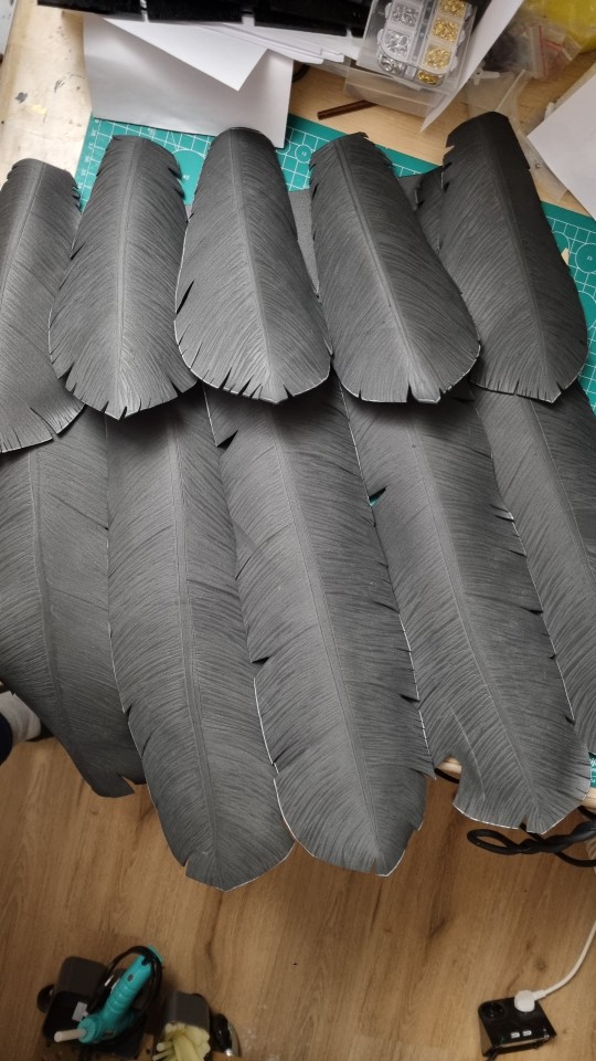
And some tail feathers that I added metal wire to for support (not pictured). I added flexbond primer today (also not pictured because I've been too busy) and sadly it covered a lot of the lines I scored in for detail, so I'll need to figure out a way to fix that. Or not.
7 notes
·
View notes
Text
Frustrations
Following other developers, learners and makers are great. It facilitates learning and gives inspiration
But one thing that is often missing from people telling about how it is going, is the failures, frustrations and problems any developer will run into.
For this reason, two of my favorite maker youtube channels are Extractions&Ire (Chemistry) and Code Bullet (machine learning). Because these madlads are brave enough to not just show their process and result, but also their failures, mistakes and errors. And how they overcome them. Not always by learning (Sometimes making a dumb mistake is not really something you can learn from...)
It's good, because it's real.
Code tutorials and guides can give the impression that the normal process of development is "Open IDE, code, fix tiny typo error, compile, success". They don't do it out of malice, but out of a want to be concise. Which is fair.
So I also want to share when things do not go so well. I have programmed Atmel's AVR Chips for quite a while now. But I have done it mostly in microchip studio(former Atmel studio) and a bit in the arduino IDE. A job I am currently applying for, uses visual studio code. Which is fair enough. So to prepare for this specific job, and to acquire this quite good-to-have skill, I want to set that up for myself First things first, since I have not done this before, I cannot know if my code would have a weird error so I want to know everything else is working first. So I write a tiny program which simply have the microcontroller increase a number every 2 seconds and write it to my PC over UART. Takes 2 minutes.... I grab one of my Arduino Nano boards and a USB cable for it. And then... I cannot flash it... Its communication protocol have troubles.
I have seen this before. It is to do with the cables not being correct. If they are USB 2.0, very little magnetic noise can cause trouble. (And you cannot tell if a cable runs USB 2.0 or 3.0 by looking at it... because the universal serial bus is not universal... Insert grump rant here) I then spend an hour finding and trying different USB A to USB B-mini cables. Give up, notes down to buy (and MARK) some USB 3.0 versions for the future. I then grab a Arduino Uni instead, as they use USB B, which is much more resistant to noise... And then spend half an hour trying to find a the cable, as I do not have a lot of them, since... nearly nothing uses them. Finally find it, and yes, the program can now be flashed. So I packed all the cables I tested back in their places, after marking them so I will(hoefully) not have to do this again. Had to take several breaks feeling depressed and grumpy, and all in all, this adventure took 4-5 hours. And now I can START on this... And this is how work sometimes is. And that is ok. It is still... VERY frustrating ...
84 notes
·
View notes
Text
It's so frustrating right now, Everything seems complicated. I want to get into building Power bank or Arduino nano at Home, In kitchen as I feel like cooking something with electronics, But it's Complicated because I don't know what is SoC or PCB boards?? Wtf is ATmega328P chip? What it is for??? Well, I'm trying and I'm trying really hard to understand it all and I still don't get it. "What can someone except for a 16 y/o" I say to myself but I should know about such stuffs, I believe.
I wanna to create a hobby or I want something to be obsessed with, incessantly into it and I have no passion, no desire for anything but whenever I try, it seems hard like really hard, I feel I lack something everytime and I feel less but never enough in myself.
-bella
#spilled words#spilled ink#words words words#writers#writers on tumblr#dark academia#spilled thoughts#writeblr#aesthetic#quoteoftheday#poetry#electronic#the mechanisms#interiors#building#cooking#i feel empty#i feel insane#feelings#bullseye#i hate everything
2 notes
·
View notes
Text
How to Use AHT10 High Precision Digital Temperature & Humidity Sensor with Arduino
Looking to measure temperature and humidity with high accuracy using Arduino? The AHT10 sensor is a compact, I2C-based module that provides reliable data, making it perfect for IoT projects, weather stations, and smart home automation.
What You’ll Learn: ✔️ How the AHT10 sensor works ✔️ Wiring it to an Arduino board ✔️ Writing & uploading the code to get readings ✔️ Tips for stable and accurate measurements
What You Need:
AHT10 Temperature and Humidity Sensor Module
Arduino Nano
0.96 inch SSD1306 OLED Display (128x64, I2C)
Breadboard
Connecting/Jumper Wires
Arduino Nano Cable
Download the Code & Library Arduino AHT10 Temperature and Humidity Sensor Module
Watch the full tutorial on YouTube:
youtube
Follow for more DIY electronics tutorials & Arduino projects!
3 notes
·
View notes
Text
medovik
#richter ursidae#811 game#811#ryker dublin#ryker 811#811 ryker#arduino nano#arduino#arduino project#electronics#electronics hobby
20 notes
·
View notes
Text
youtube
#AC voltage measurment#arduino nano#voltage sensor#ZMPT101B#TM1637 4 Digit Seven Segment Display Module#TM1637#buzzer module#arduino IDE#IOT#smart city#smart home#internet of things#Youtube
1 note
·
View note
Text

What are you??? Where are you coming from???
It shows up when I do a waveform lookup table and it seems to be around the same voltage on the sine and the triangle, but only on the descending side.
Actually I haven't tried a descending sawtooth, so I'll have to give that a try. Maybe it's something related to the PWM. Honestly I'll get a DAC anyway for any fully digital oscillator, so maybe it's time to just put this on hold while I work on the DCO.
11 notes
·
View notes
Text

4 notes
·
View notes
Text
4x4x4 PCB LED CUBE
youtube
Bring life to your home with this enchanting 4x4x4 LED cube. From static to flashing, chasing, or fading this cube can be programmed to display many different types of 3D LED transitions. This customizable PCB LED cube is super easy to make and fun to have in your home. Go ahead and create a forest of these cubes using various color LEDs to enhance the beauty of your Christmas Tree this Christmas. This cube has 64 Blue LEDs organized in 4 layers. These LEDs are wired up to an Arduino Nano. Each LED can be addressed individually using Arduino IDE, enabling it to display amazing 3D transitions! There are hundreds of tutorials of these cubes made using exposed metal wires and by using crazy soldering techniques, which just gives me shivers. In this tutorial I'll show you guys how to make this super simple 4x4x4 PCB LED cube "without over complicating anything". With just basic soldering skills, you can create this PCB cube and light up your living room making everyone jealous.
3 notes
·
View notes
Text
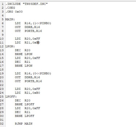
First ATTINY85 project!
(warning: video has actual flashing LED lights)
[ Video ID: A breadboard with a Blue LED on top of an 8-pin DIP Integrated Circuit on it. The Blue LED is flashing rapidly. There are other components on the breadboard in the background. End ID ]
Last week I bought some ATTINY85 Microprocessors to experiment and work with :) With my W65C02 project on hold until I can afford an oscilliscope, and my Radio project delayed because I can’t quite figure out how to reverse engineer the 8 pins on the volume knob, I wanted something else to work with. I’ve been wanting to mess with Atmel microprocessors (Arduino Uno runs on an Atmel ATMEGA328), and now’s a good chance!
I’m jumping straight to assembly with the ATTINY85; I don’t know any C/C++ code, and also I’m familiar with other processor Assembly languages, so I might as well. And other than different names for functions, it’s been pretty easy so far! Something I’m not used to is that this processor, despite being pathetically tiny, has 32 registers; I’m used to working with 8 Max.
Anyways, for the code explanation: When the processor first starts, it turns on PINB0, which is physical pin 5 on the processor. Then, after counting to 256 256 times, it turns off PINB0 for another 256^256 counts. I’m away from home while writing this, so my notes arn’t here, but if I remember correctly it came up to 200k microseconds? That adds up to about 400 nano seconds per on/off cycle, or 2.5 flashes per second. I can add in another loop to make it last longer, but before I do that I’d like to look about to see if there’s a smarter way to tackle this.
My next step after this, is to figure out how to get this processor to read digital inputs: My next project is to finally do something with my box of telephone rotary dials. I already have one spec’ed out for breadboard testing. I would LOVE to show it, but Tumblr has a One Video Per Post limit :(
13 notes
·
View notes