#CWDM ITU Channel
Explore tagged Tumblr posts
Visit Tumblr Blog
Explore Tumblr blogs with no restrictions, modern design and the best experience.
Last Seen Tumblr Blogs


Fun Fact
Hackers stole 65M passwords from Tumblr in 2013.
Text
Introduction to 40GBASE QSFP+ Optical Modules
40GBASE Optical modules are different from optical handsets with a 40Gbps transmission rate, in which the QSFP is the primary structure factor. Also, the 40G QSFP+ Modules are the most extensively applied optical handsets. In this article, 10Gtek will present distinctive organization arrangements of the most overall 40G QSFP+ handsets to assist you with having a simpler understanding and better determination of the modules.
Highlights and Benefits of 40G QSFP+ Transceiver
Hot-pluggable to 40G Ethernet QSFP+ port
QSFP+ MSA consistent and interoperable with other IEEE-agreeable 40G interfaces
RoHS affirmed and checked unrivaled execution, solidness, and dependability
Rapid electrical interface dependent on IEEE 802.3ba agreeable
4 Parallel paths plan of SR4, ESR4, PSM LR4, and PSM IR4
4 CWDM paths MUX plan of LR4, IR4, and ER4
Low force utilization under 3.5W
40G QSFP+ SR4 and 40G QSFP+ ESR4 Transceivers
The signs' conveyance of 40G QSFP+ SR4 handset is sent through four autonomous full-duplex channels. MPO/MTP Connector is a basis applied to the Transceiver in 40G information transmission, and MMF(Multi-Mode Fiber) is needed to work over inside the handset. At the point when it's running over the OM3 optical fiber jumper the transmission separation is 100m, while the scope can be 150m when it's running over the OM4 optical fiber jumper.

40G QSFP+ ESR4 is a similar working rule as 40G QSFP+ SR4 however with an advanced separation of transmission up to 300m over OM4 optical fiber jumper. It tends to be considered as an updated form of 40G QSFP+ SR4 handset.
40G QSFP+ BIDI Transceiver
The QSFP+ BIDI handset is created to address the difficulties of fiber foundation by giving the capacity to send full-duplex 40G traffic more than one duplex MMF link with LC connectors(Figure 2). At the end of the day, this handset upholds 40G association more than one sets of MMF links while permitting 40G to be sent utilizing a similar foundation as 10G (10GBASE-SR) without the need to include any strands.
Examination of 40G QSFP+ BIDI and 40G QSFP+ SR4
40GBASE-SR BIDI handset eliminates 40G cabling cost hindrances in server farm organizations. It gives colossal investment funds and effortlessness contrasted with other 40G QSFP+(MMF) transceiver(QSFP+ SR4). Additionally, it permits associations to move the current 10G cabling framework to 40G at no expense and to grow the foundation with low capital speculation.

40G QSFP+ PSM IR4 and 40G QSFP+ PSM LR4 Transceivers
QSFP+ PSM IR4/LR4 is an exceptionally coordinated four-channel optical handset with the benefits of the high thickness of port and lower cost. The optical port embraces a PSM(Parallel Single Mode) innovation and a four-way equal plan MPO/MTP interface which empowers the transmission separation up to 1.4km of IR4 and 10km of LR4. It has been planned with structure factor, optical/electrical association, and computerized analytic interface consistent with MSA(Multi-Source Agreement), these highlights are very attainable to meet the harshest outer working conditions including temperature, moistness, and EMI interface.
The handset can run through the I2C two-wire sequential interface which is accessible to send and get more intricate control signals and to get computerized symptomatic data. By correlation with 40G QSFP+ SR4, they are both similarly of working yet QSFP+ PSM IR4/LR4 is working over SMF(Single Mode Fiber) that is the equal optical signs are conveyed through eight single-mode strands.
40G QSFP+ CWDM LX4/LR4 Lite/LR4/ER4 Transceiver
Recognized from DWDM for example Thick Wavelength Division Multiplex, CWDM known as Coarse Wavelength Division Multiplex is an inventive innovation for moving a lot of information between locales. It builds transfer speed by permitting distinctive information streams to be sent all the while over a solitary optical fiber organization. Thusly, WDM amplifies the use of fiber and assists with streamlining network speculations.
QSFP+ LX4 is an optical module planned particularly for working over both SMF and MMF with transmission separation of up to 150m on OM4 MMF and 2km on SMF. The focal frequencies of the 4 CWDM channels are 1271nm, 1291nm, 1311nm, and 1331nm as individuals from the CWDM frequency framework characterized in ITU-T G.694.2. There is a duplex LC connector for the optical interface and a 148-pin connector for the electrical interface. For applications over SMF, the handset is utilized as a QSFP+ LR4 Lite module and SMF links are legitimately associated with the LC connectors of the module.
QSFP+ LR4 Lite/LR4/ER4 Module bolsters the connection length of up to 2km, 10km, and 30km individually by working over a standard pair of G.652 SMF with duplex LC connector. Inside the gadget, the 40G Ethernet signals are sent more than four frequencies which are figured out how to multiplex and demultiplex. There are 4 information channels to send flags simultaneously. At the sending side, the 4 channels of optical signs are consolidated together by multiplexer while at getting end there is a breakdown handled into 4 channels of optical signals by the demultiplexer. The module includes high thickness, minimal effort, rapid, huge limit, and low force utilization.
CWDM versus PSM, What's The Difference?
From an optical handset module structure perspective, PSM appears to be more financially savvy since it utilizes a solitary uncooled CW (ceaseless wave) laser which parts its yield power into four incorporated silicon modulators. Additionally, its exhibit fiber coupling to an MTP connector is generally less complex. Nonetheless, from a framework perspective, PSM would be more costly when the connection separation is long, basically because of the way that PSM utilizes 8 optical single-mode filaments while CWDM utilizes just 2 optical single-mode strands.
Tantamount with Third-Party QSFP+
All 10Gtek's 40G QSFP+ Transceiver is benevolently viable with outsider QSFP+ gadget, for example, Cisco, Extreme, Brocade, Juniper, HP, Dell, Arista, Huawei, and other known brands. Our 40G QSFP+ handset will give you a phenomenal answer for set up network association without costly expense.
2 notes
·
View notes
Text
CWDM/DWDM ITU Channel Руководство
CWDM (Грубое Спектральное Мультиплексирование) и DWDM (Плотное Волновое Мультиплексирование) позволяют носителям предоставлять больше услуг по своей существующей волоконной инфраструктуре путем объединения нескольких длин волн на одном волокне. FS предлага��т серию решений и товаров CWDM/DWDM, которые помогают снизить выделение волокон надежным и экономичным способом.
CWDM ITU Channel Обзор
ITU-T G.694.2 определяет длину волны 18 (C1-C18) для CWDM передачи в диапазоне от 1270 до 1610 нм, разнесенных на расстоянии 20 нм. Ниже представлена полная сетка CWDM. Каждый канал CWDM прозрачен для скорости и типа данных, означая, что любое соединение SAN, WAN, голосовых услуг и видеоуслуг может транспортироваться одновременно по одному волокну или паре волокон.
Быстрый Просмотр FS CWDM Оптического Модля
FS CWDM модули доступны со всеми 18 длиной волны CWDM, включая CWDM SFP, CWDM SFP+, CWDM XFP и 3G SDI CWDM SFP модули. Эти трансиверы CWDM могут применяться при передаче данных с 20 до 120 километров.
20KM CWDM Модули
CWDM SFP 20KM
CWDM SFP+ 20KM
CWDM XFP 20KM
3G SDI CWDM SFP 20KM
40KM CWDM Модули
CWDM SFP 40KM
CWDM SFP+ 40KM
CWDM XFP 40KM
3G SDI CWDM SFP 40KM
80KM CWDM Модули
CWDM SFP 80KM
CWDM SFP+ 80KM
CWDM XFP 80KM
120KM CWDM Модули
CWDM SFP 120KM
FS CWDM Mux/Demux Решение
В дополнение к различным модулям CWDM/DWDM, FS также предоставляет широкий спектр модулей CWDM Mux/Demux, который выступает в качестве основного структурного элемента при расширении и обновлении сети. FS CWDM Mux/Demux имеет несколько разных типов в отношении типа линии, номера канала и специальных портов.
DWDM ITU Channel Обзор
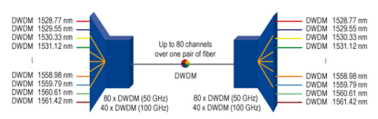
ITU G.694.1 стандартный регион DWDM составляет от 1528,77 нм до 1563,86 нм, который находится в основном в диапазоне C. DWDM может иметь интервал длин волн 100 ГГц (0,8 нм) для 40 каналов или интервал 50 ГГц (0,4 нм) для 80 каналов. Ниже показана полная сетка каналов для DWDM 100 ГГц.
Быстрый Просмотр FS DWDM Оптического Модля
FS CWDM модули доступны со всеми 44 длинами волн DWDM, включая DWDM SFP, DWDM SFP+, DWDM XFP и Tunable DWDM модули, которые поддерживают дальность передачи данных макс.до 120 км. Перестраиваемые модули Tunable (DWDM) могут способен поддерживать определенный канал в оптической сети DWDM, позволяя удаленно изменять длин�� волн в программном обеспечении.
40KM DWDM Модули
DWDM SFP 40KM
DWDM SFP+ 40KM
DWDM XFP 40KM
80KM DWDM Модули
DWDM SFP 80KM
DWDM SFP+ 80KM
Tunable DWDM SFP+ 80KM
DWDM XFP 80KM
Tunable DWDM XFP 80KM
120KM DWDM Модули
DWDM SFP 120KM
FS DWDM Mux/Demux Решение
DWDM Mux/Demux используется в сетях дальнего расстояния, чтобы облегчить истощение волокна и затраты, связанные с запуском нового волокна. Каждый канал DWDM может передать данных макс.до 100G, а расстояния более 1000 километров могут быть достигнуты с использованием оптических усилителей.
CWDM ITU Channel
0 notes
Text
White Paper: CWDM + DWDM = Increased Capacity
One way of increasing capacity in fiber optic links is to add DWDM over existing CWDM
April 2023
by Robert Isaac
Ghostwritten by Scott Mortenson
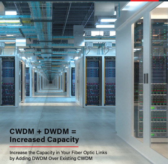
For years, service providers have been using Coarse Wavelength Division Multiplexing (CWDM) to increase the capacity of fiber optic links. CWDM filters offer up to 18 ITU (International Telecommunication Union) defined wavelengths and has been an ideal way to transport 1Gbps and 10Gbps circuits over a single fiber span.
What we are seeing now seems to be an uphill climb for CWDM applications. There appears to be a bandwidth growth requirement, and decreased support for CWDM from some equipment manufacturers.
With CWDM support from manufacturers dwindling and the need for capacity increasing at an exponential rate, the question becomes “How do we increase the capacity without forklifting the existing CWDM?”
One answer can be using DWDM over the existing CWDM.

Figure 1
The Concept
Because CWDM is built with channels that are spaced 20nm apart and often have a 10-13nm passband per wavelength (see Figure 1 above), DWDM makes a lot of sense. DWDM filters are built with much smaller channel spacing (.4nm/.8nm/1.6nm), so these wavelengths can be combined and will pass through the ~13nm passband of CWDM channel. For this example, we will focus on standard DWDM filter channels that are in the C-Band (1525nm-1565nm) spectrum and 100Ghz-spaced as this is the most common and supported DWDM application.
If it is warranted this same principle can be applied using DWDM channels in the L-Band (1570nm-1610nm) as well as using channels that are only 50Ghz-spaced to increase channel count and density, and be easily supported with tunable SFP+ optics.

Figure 2
Figure 2 shows how cascading DWDM filters over an existing CWDM span would connect. In this example we use a standard, off the shelf, DWDM filter that is equipped with 8 channels (ITU Ch 52-59).

Figure 3

Figure 4
Figures 3 and 4 show how 20 DWDM channels could be added across the 1530nm CWDM port and 30 DWDM channels can be added using the 1550nm CWDM port using C-band channels. We could apply this same philosophy to the 1570nm, 1590, and 1610nm ports as well but would require L-Band DWDM channels which aren’t widely supported today.
The Challenge
Now that we know a standard 8 Channel CWDM can be expanded to include another 50 channels you may be thinking “What are the potential downsides to using DWDM over CWDM?” and that would be a very good question to ask.
This concept has been available for many years and hasn’t become part of the mainstream deployment strategy for many network operators. Why not? The only limitation to using this concept from a performance standpoint is the added insertion loss of having both the CWDM and DWDM filters between the transceivers.

Figure 5
Figure 5 shows the logical end-to-end for 8 channels of DWDM over an existing CWDM connecting two sites 30km apart. To keep losses lower, we will limit the new channels being added to 8 DWDM channels. Understanding that 10G DWDM optics have an overall power budget of 23db, we can see that adding the DWDM filters brings the overall link loss to 21.5db which falls just inside the power budget.
Because DWDM optics are built for longer reaches with higher power budgets — and CWDM is often used on shorter fiber spans, say under 30km — the insertion loss should be a non-issue. And if the loss is an issue, DWDM channels can be amplified (unlike CWDM), so placing a low-cost EDFA between the CWDM and DWDM filters could help extend the reach well beyond even 30km.
Reluctance to this concept also seems to come from not fully understanding the simplicity of passive WDM or even how to manage the engineering, installation, records, and inventory for having both technologies within the same span. If those challenges can be overcome, overlaying DWDM onto your existing CWDM can be a very efficient and cost-effective way to respond to the exponential need for bandwidth we are facing in today’s technology.
For network operators and service providers who have made a significant investment in CWDM and facing the need for bandwidth growth, this concept should be considered. Passive DWDM filters can be deployed quickly without impacting existing traffic, are a very low-cost alternative to complex active systems, and can equip your network for the future in very short order. Add the operational efficiency of 10G tunable DWDM optics, and this could be a home run for your network.
Demystifying DWDM for the DCI
If it is so easy and inexpensive, why aren’t all the data centers defaulting to using this on every fiber end? Well, that’s where things get a little tricky.
Whenever you say “DWDM” to a Data Networking person (and even some Service Provider engineers), their default reaction tends to go straight for large, complex, and expensive DWDM systems. Like Reconfigurable Optical Add Drop Multiplexing (ROADM) arrangements that are completely automated and perform optical switching, sub-signal aggregation, and even some L2 functions.
The truth is, DWDM is simply the combination and separation of circuits by wavelength — and only a small part of those larger systems. It is the basic technology that allows users to put 40+ distinct circuits on a given fiber, then separate them at the far end to connect to the individual switch ports.
As stated in the previously, this is often done passively, requiring no electrical power, software, annual maintenance agreement, etc. — and at a fraction of the cost of those more complex active systems.
So again, I ask: “Why aren’t more data center interconnects using this technology?”
Well, DWDM system design — or transport engineering — is usually not taught during Data Networking education courses. DWDM or transport are often thought of as completing ways of architecting a network, which means there are usually two camps: You are either a Data Network Engineer, or a Transport Engineer. Either way, one typically needs the other at some point in their network.
This is not to say you don’t need complex, software-controlled transport devices in your network. The truth is you likely do. What we are singling out here are a few applications where you can get what you need: Fiber capacity between two places quickly, inexpensively, and without sending anyone to school to get certified.
These applications can be:
• Point-to-Point Data Center Interconnects (DCI) on leased, or owned fiber. • Connections between campus facilities. • Network facilities between rooms or floors.
Using Passive DWDM can:
• Reduce or eliminate leased or new fiber builds. • Maximize the data rate per-fiber of installed fiber plants. • Drastically reduce Capex cost of high-capacity switches, complex DWDM systems, and reliance on service providers to maintain the connections. • Increase capacity of DCI connections in days not months.
How can we do this in a way we can understand?
It really comes down to Optical Link Engineering.
If you take the physical map of your network and zoom in on one span where there is a capacity bottleneck, it becomes a lot easier. For simplicity’s sake, we will focus on connecting 10G switch ports, across a single span between 2km and 50km long, making the math fairly simple.
For these locations, we just need to focus on two primary factors: Link Budget vs Link Loss, and Dispersion.
Link Budget vs. Link Loss
Every optic or transceiver has a minimum transmit power, and a minimum receiver sensitivity. By subtracting these two values, you are left with the link budget — or the total amount of power loss the signal can experience and still be legible by the receiver.
In a standard connection, you would calculate (or measure) the total loss of the fiber, patch panels, cassettes, and splices between the two optics. And if that is less than the link budget, then it should work . . . right?
Passive DWDM only adds a little more math to the Link Engineering. The optics at each end would need to be specific DWDM optics, and the filters will add more insertion loss at each end — but it is still, pretty much the same math.
For 10G DWDM optics, the link budget is typically in the 23db range. If a fiber span, with DWDM filters, has less than 23db of loss, the link should work. It’s simple math.
Or is it?
Dispersion
Another important factor we account for is Chromatic Dispersion (CD). This is a characteristic of single-mode fiber where, as a signal travels along a fiber route, it spreads out and can arrive at the far end slightly ahead or slightly behind schedule, making it difficult to be deciphered by the receiver.
The optics we are using will also establish how much dispersion it can tolerate before the signal becomes undetectable. This value is typically measured in picoseconds per kilometer per nanometer (ps/km/nm) or even simply by the optic’s distance rating. For instance, a DWDM optic-rated for 80km is often limited to 1360 ps/nm/km of dispersion. This is calculated based on traveling 80km on SMF28 type fiber with a CD rating of approximately 17 ps/nm/km.
So, there you have it. If your link falls inside the specifications defined by the optics on each end, you can deploy passive DWDM to maximize the capacity of your fiber plant, and save loads of time and money.
But what if the span exceeds the link budget or dispersion rating? No problem! The addition of Erbium Doped Fiber Amplifiers (EDFA) — to boost the signal power and/or passive Dispersion Compensation Modules (DCM) to account for excess dispersion between the DWDM filters — can help extend the reach and ensure the optics on each end perform to expectation to years to come.
Often when Transport Engineers speak to Data Network Engineers, it can seem like they are speaking different languages. That is to be expected. Specialized jargon or terminology, approaches to problems, and education can be vastly different.
If what your network truly needs is fiber capacity, lower cost of fiber infrastructure, and flexibility of lightning-fast circuit turn-up, passive and even amplified DWDM networks could be the perfect solution.
The 40-channel, two-fiber DWDM solution using 10g SFP+ optics is a great way to get 400G of capacity for links up to about 60km without the need for amplification or dispersion compensation. But what if you want higher data rates on the link? This is where things get a little tricky.
If we remove coherent optics from consideration due to the expense and complexity of deploying them, we see a pattern emerge. Here is a quick snapshot of the specifications of DWDM optics (non-coherent) we could consider:

Figure 6
That table attempts to remove a bunch of “noise” or complexity in determining if a simple point-to-point two-fiber solution will work. What we see when we review those specs is that as data rate increases, the unmodified reach and power budget both decrease.

Figure 7
Given these values, we can use the optical reach and power budget — along with the logical diagram shown in Figure 7 — to determine how long of a cross-connect we can achieve.
If we assume the 40-channel filter has a high-performance loss of 3db each, the patch panels have a loss of 0.5db each and the fiber loss is 0.25db per km (ITU-T G.657.A1 and G.652.D or better), then we can work backwards to see what the total span distance is per optic/data rate.

Figure 8
Reviewing the numbers in Figure 8, we can see that once you go beyond the 10G data rate, the unmodified reach becomes the limiting factor. For this illustration, we can expect to be able to establish some versatile, yet high-capacity, cross-connects.
We had already reviewed the capacity of a passive 40-channel system using 10Gbps optics and know that it can support 400Ghz worth of capacity. Using the same methodology, we can create links with a total line capacity of 1Tbps @ 25Gbps per channel up to ~15km, 1.6Tbps @ 40Gbps per channel up to ~8.8km, and a 4Tbps total capacity up to ~1.5km in fiber length. Knowing this can help reduce the total number cross-connects needed between any two points.
Also, worth noting: Not all channels need to be the same data rate. If the link distance is designed to work with 100Gbps links (or approximately 1.7km), that same link will be able to support 10G, 25G and 40G channels as well.
Summary
Earlier we mentioned we were “removing a lot of noise” — and then continued to make a great deal of assumptions to come up with these numbers. For instance, Forward Error Correction (FEC) is required and must be available on the host device for the links 25Gbps and higher. We made assumptions about fiber type, used calculated losses for the fiber spans, and assumed the total SFP+, SFP28, QSFP+, and QSFP28 ports were available at each end.
What this proved is that by combining passive filters and DWDM optics, we can increase the capacity as much as 40x per cross-connect pair. All this needs no power (except the switches), can be turned up very quickly, requires only 1RU of rack space (not counting the switches or patch panels), and adds zero latency.
As should be clear by now, this is not meant to be taken as gospel, and every effort should be made to know the optic specifications you are considering, the fiber type of the cross-connect, and have measured fiber loss and dispersion values before deploying.
When planned correctly, your CWDM plus DWDM can mean increased capacity without a big financial outlay. And your network can perform better as well.
0 notes
Text
CWDM: What You Need to Know
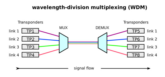
Wavelength division multiplexing (WDM) is a technology for transporting large amounts of data between sites. It increases bandwidth by allowing different data streams to be sent simultaneously over a single optical fiber network. There are two main types of WDM systems: coarse wavelength division multiplexing (CWDM) and dense wavelength division multiplexing (DWDM). This article provides some knowledge about CWDM.
What is CWDM?
Coarse Wavelength Division Multiplexing (CWDM) is a wavelength multiplexing technology for cities and access networks. The word coarse means the wavelength spacing between channels is relatively large. Furthermore, CWDM is an ideal solution for short-range applications and is used to improve the transmission capacity of optical fiber and the utilization of optical fiber resources.

CWDM Operating Principle
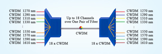
CWDM was standardized by the ITU-T G.694.2 based on a grid or wavelength separation of 20 nm in the range of 1270-1610 nm. It can carry up to 18 CWDM wavelengths over one pair of fibers. Each signal is assigned to a different wavelength of light. Each wavelength does not affect another wavelength, so the signals do not interfere. Each channel is usually transparent to the speed and data, so the voice, video, and other services can be transported simultaneously over a single fiber or fiber pair.
CWDM Network Component
A multiplexer (Mux) combines multiple wavelength channels on a single fiber, and a demultiplexer (Demux) separates them again at the other end. A Mux/Demux set-up is used to increase the end-to-end capacity of a deployed fiber. The Mux is located in the central office, and the Demux is located in the cabinet or splice closure from which the fibers go to their destination in a star-shaped topology.

Features and Benefits
CWDM provides low insertion loss, low polarization-dependent loss, low cost, low-temperature sensitivity, low power consumption, high channel isolation, high data rate, high stability, high reliability, small size, and ease of installation and deployment.
Applications
CWDM is used in metropolitan area networks (MAN), local area networks (LAN), storage area networks (SAN),10-gigabit ethernet, passive optical networks (PON), WDM transmission systems, FTTx networks, 5G front-haul, data centers, online monitoring, fiber optic amplifier, etc.

Conclusion
CWDM has become the preferred solution for increasing the bandwidth of metro/regional and optical access networks. And it has proven to be sufficiently robust, low-cost, and reliable for upgrading the optical network to accommodate future growth. Sun Telecom specializes in providing one-stop total fiber optic solutions for all fiber optic application industries worldwide. Contact us if any needs.
1 note
·
View note
Text
QSFP+ 40G LR4 2KM
https://www.china-tscom.com/products/qsfp-40g-lr4-2km/
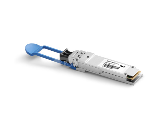
The QSFP+ 40G-LR4-2km module is a highly integrated 4x10G transceiver focused on reach, bandwidth, density and cost for high port-count 40G systems, and client-side 40G interfaces. The 40G QSFP+ LR4 Lite transceiver is designed for applications based on the IEEE802.3ba 40GBASE-LR4 standard of up to 2km reach.
Features of QSFP+ 40G LR4 2km
l Reach: 2 km via SMF
l Uncooled CWDM DFB lasers, directly modulated
l Using ITU G.694.2 wavelength grid at 1271, 1291, 1311, and 1331nm
l User controllable Transmit Input Equalization and Receiver Output Amplitude
l MSA-compliant performance monitoring via I2C interface
l Fiber connector: SMF LC duplex connector
l Compliant with QDR/DDR InfiniBand data rates
l Hot-pluggable electrical interface
l 0–70°C operating temp
l Power dissipation < 3.5W
l RoHS6 compliant (lead-free)
Applications of QSFP+ 40G LR4 2km
l 40G Ethernet
l InfiniBand QDR and DDR interconnects
Specifications of QSFP+ 40G LR4 2km
Optical Transmitter Performance|Optical Receiver Performance|Recommended Operating Environment
Parameter
Symbol
Min
Typical
Max
Unit
Center Wavelength
Ch0
λ0
1264.5
-
1277.5
nm
Ch1
λ1
1284.5
-
1297.5
nm
Ch2
λ2
1304.5
-
1317.5
nm
Ch3
λ3
1324.5
-
1337.5
nm
Bit Rate per Channel
B
10.3125
-
-
Gb/s
Total Average Launch Power
POUT
-
-
8.0
dBm
Side Mode Suppression Ratio
SMSR
30
-
-
dB
Average launch power, each lane
-6.8
-
2.0
dBm
Optical Modulation Amplitude (each lane)
OMA
-6.0
-
3.5
dBm
Optical Modulation Amplitude (OMA) - TDP, per lane (min)
-7.8
-
dBm
Transmission & dispersion penalty,
each lane
TDP
-
-
2.3
dB
RIN12 OMA
-
-
-
-128
dB/Hz
Transmitter Reflectance
-
-
-
-12
dB
Extinction Ratio
ER
3.5
-
-
dB
Transmitter eye mask definition {X1, X2, X3, Y1, Y2, Y3}
{0.25, 0.4, 0.45, 0.25, 0.28, 0.4}
Average launch power of OFF transmitter, each lane
-
-
-
-30
dBm
Optical return loss tolerance
-
-
-
20
dB
Pin Descriptions of QSFP+ 40G LR4 2km
Pin Definition of QSFP+ 40G LR4 2km
Pin
Symbol
Name/Description
1
GND
Ground
2
Tx2n
Transmitter Inverted Data Input
3
Tx2p
Transmitter Non-Inverted Data Input
4
GND
Ground
5
Tx4n
Transmitter Inverted Data Input
6
Tx4p
Transmitter Non-Inverted Data Input
7
GND
Ground
8
ModSelL
Module Select
9
ResetL
Module Reset
10
Vcc Rx
+3.3 V Power supply receiver
11
SCL
2-wire serial interface clock
12
SDA
2-wire serial interface data
13
GND
Ground
14
Rx3p
Receiver Non-Inverted Data Output
15
Rx3n
Receiver Inverted Data Output
16
GND
Ground
17
Rx1p
Receiver Non-Inverted Data Output
18
Rx1n
Receiver Inverted Data Output
19
GND
Ground
20
GND
Ground
21
Rx2n
Receiver Inverted Data Output
22
Rx2p
Receiver Non-Inverted Data Output
23
GND
Ground
24
Rx4n
Receiver Inverted Data Output
25
Rx4p
Receiver Non-Inverted Data Output
26
GND
Ground
27
ModPrsL
Module Present
28
IntL
Interrupt
29
Vcc Tx
+3.3 V Power supply transmitter
30
Vcc1
+3.3 V Power Supply
31
LPMode
Low Power Mode
32
GND
Ground
33
Tx3p
Transmitter Non-Inverted Data Input
34
Tx3n
Transmitter Inverted Data Input
35
GND
Ground
36
Tx1p
Transmitter Non-Inverted Data Input
37
Tx1n
Transmitter Inverted Data Input
38
GND
Ground
Important Notice of QSFP+ 40G LR4 2km
Performance figures, data and any illustrative material provided in this data sheet are typical and must be specifically confirmed in writing by T&S before they become applicable to any particular order or contract. In accordance with the T&S policy of continuous improvement specifications may change without notice.
The publication of information in this data sheet does not imply freedom from patent or other protective rights of T&S or others. Further details are available from any T&S sales representative.
0 notes
Text
Do you know The difference between CWDM transceiver and DWDM transceiver?
Do you know The difference between CWDM transceiver and DWDM transceiver?
DWDM technology multiplexes the tight spectral spacing of a single optical fiber carrier in a given fiber to take advantage of the transmission performance that can be achieved. DWDM wavelength spacing is very tight, because the closer the spacing is, the more channels per fiber will be reused, and thus the higher the bandwidth. The international telecommunication union (ITU) g. 694.1 standard…
View On WordPress
0 notes
Text
Overview of CWDM vs DWDM
As we know, WDM (wavelength-division multiplexing) is a technology that can multiplex a number of optical carrier signals into a single optical fiber by using different wavelengths of laser light. Since there is a tremendous demand for high bandwidth, WDM becomes popular in the market. There are two key types of WDM technologies: CWDM (coarse wavelength division multiplexing) and DWDM (dense wavelength division multiplexing). Then, what are they? What’s the difference between them? This article will have a brief overview of CWDM vs DWDM to help you understand the differences between CWDM and DWDM technology.
What Is CWDM Technology?
CWDM (coarse wavelength division multiplexing) is a wavelength multiplexing technology for cities and access networks. The word “coarse” means the wavelength spacing between channels is relatively large. In general, CWDM has 18 different channels with a wavelength range from 1270 nm to 1610 nm. Because of the high data rates and low cost, CWDM is widely used in large campuses and data centers. Hence, it has become the preferred method for increasing the bandwidth of metro and optical access networks at a low cost.

What Is DWDM Technology?
DWDM is an optical multiplexing technology used in fiber optics to increase the bandwidth, which resembles CWDM technology. The word “dense” here means the wavelength channels are very close to each other. According to ITU regulations, DWDM has 100GHz (0.8nm) wavelength spacing for 40 channels or 50GHz (0.4nm) spacing for 80 channels. Because of its ability to handle so much data, DWDM is widely used in telecommunications and cable companies and becomes an integral part of their core networks gradually.
CWDM vs DWDM: What Are Their Differences?
Both CWDM and DWDM use multiplexed wavelengths of laser light to increase bandwidth capacity. However, they still have a lot of differences given the following aspects: channel spacing, transmission distance, modulation laser and cost. Just read on to find the details.
Channel Spacing
From the words “coarse” and “dense”, we can see the difference in channel spacing that CWDM has a wider spacing than DWDM. CWDM can provide 18 wavelengths (from 1270 nm to 1610 nm) with the channel spacing of 20 nm. While DWDM can carry 40, 80 or even 160 wavelengths (from 1563.86 nm to 1528.77 nm) with a narrow wavelength spacing of only 1.6, 0.8 or even 0.4 nm. It is simple to see that DWDM has a better performance than CWDM when transmitting a greater number of multiplexed wavelengths on a singer fiber.
Transmission Distance
DWDM technology is able to have a long transmission by keeping the wavelength highly integrated. The amplified wavelengths can make DWDM suffer less interference over a larger run of cable. Unlike DWDM technology, CWDM can’t travel unlimited distance as the wavelengths are not amplified. Usually, CWDM can transmit data up to 160 km.
Modulation Laser
DWDM technology uses the cooling laser, which is a technology that atomic and molecular samples can be cooled down to near absolute zero. Conversely, CWDM technology uses the uncooled laser, which can’t ensure better performance, higher safety, and long life span like DWDM.
Cost
Generally, the price of DWDM is four or five times higher than that of CWDM. The higher cost of DWDM mainly contributes to cooling laser technique which can realize the temperature tuning. But nowadays, as DWDM technology becomes more and more popular, the price of DWDM transceiver becomes cheaper than CWDM transceiver.
A detailed comparison between CWDM and DWDM technology is in the table below.

Conclusion
From the introduction of CWDM vs DWDM, we know that CWDM and DWDM are two technologies based on WDM technology with different wavelength patterns and applications. Usually, CWDM costs less and its performance is far behind DWDM. Both the cost and requirement should be taken into consideration. You’d better think twice before choosing a CWDM or DWDM system.
0 notes
Text
The Advantage of CWDM in Metropolitan Area Network
Due to the fast improvement of information benefits, the speed of system union is quickening, MAN is turning into a focal point of system development, showcase rivalry weight makes the telecom administrators increasingly delicate to the expense of the system. Gone for the interest of the market, ease MAN CWDM items emerge right now.

With full range CWDM group (FCA) vivaciously advance of CWDM Technology and ITU-T for the institutionalization of CWDM, it makes CWDM innovation hardware producers and administrators be the focal point of consideration. The ITU-T fifteenth the group through CWDM wavelength matrix of standard G.694.2, and become an achievement in the historical backdrop of the advancement of CWDM innovation. The fifteenth group likewise advances the meaning of CWDM framework interface right application draft standard. Shanghai chime and different organizations in China in the institutionalization of CWDM innovation likewise has made a certain commitment; pertinent residential guidelines are additionally under talk.
As the development of the market request and the institutionalization of CWDM innovation quickly, numerous correspondence hardware makers, for example, Nortel, Ciena, Huawei, Alcatel Shanghai chime (asb), fire system created related items and add a wide scope of utilization in the market.
CWDM the framework is a minimal effort WDM transmission innovation towards MAN access layer. On a fundamental level, CWDM is utilizing optical multiplexer to various wavelengths of light to reuse the sign to single fiber optic transmission, at the connection of the less than desirable end, with the guide of photolysis of multiplex fiber blended sign is disintegrated into various wavelength signal, associated with the comparing getting gear. What's more, the primary the distinction with DWDM is that: contrasted with the 0.2nm with 1.2 nm wavelength separating in DWDM framework, CWDM Wavelength Spacing is more extensive, wavelength dividing of 20 nm industry acknowledged measures. Every wavelength of the band spread the single-mode fiber arrangement of O, E, S, C, L band, etc.
In view of CWDM framework has wide wavelength dividing and low interest to specialized parameters of the laser. Since wavelength dividing up to 20 nm, the framework most extreme wavelength move can reach - 6.5℃~+6.5 ℃, the outflow the wavelength of laser accuracy can be up to +/ - 3nm, and the working temperature run (- 5℃~70℃), wavelength float brought about by temperature change is still in the admissible range, laser without temperature control the instrument, so the structure of the laser significantly disentangled yield improvement.

Moreover, the bigger wavelength separating implies recuperation gadget/arrangement of multiplexer structure is significantly disentangled. CWDM framework, for instance, the CWDM Filter layer covering layer can be diminished to 50, and DWDM arrangement of 100 GHZ channel film covering layer number is around 150, bringing about expanded yield, cost decrease, and the channel provider has enormously expanded challenge. CWDM channel cost not exactly the expense of DWDM channel about over half, and with the expansion of computerization generation innovation, it will be further decreased.
Still CWDM situating the short separation transmission in the metropolitan zone organize (inside 80 km), and the channel rate is commonly not more than 2.5 Gbps, so there is no requirement for light intensification, scattering, nonlinear and different contemplations in the transmission lines, at that point you can make the framework is streamlined.
By methods for a portion of these, by growing wavelength dispersing and improving hardware, the expense of optical channel made the CWDM framework unit can be diminished to 1/2 or even 1/5 of the DWDM framework, it has solid focal points in the metropolitan territory system access layer.
Fiber-mart.com is a very expert store of giving optical fiber items, in the event that you need to know increasingly related items data, welcome to get in touch with us.
#Buy LC Cable#Sc Cable#FC Cable Online#LC Cable Manufacturer#OFNP Patch Cable#OFNP Patch Cable Manufacturer
3 notes
·
View notes
Text
THE 4 ADVANTAGES OF CWDM TECHNOLOGY NETWORKS
Coarse Wavelength Division Multiplexing s one of the optical transport technologies that make use of the light wavelengths and fiber high band capacities along with SDH and DWDM technologies. CWDM is not the latest technology developed for optical transmission but it has its own advantages for choice in particular circumstances.
Simpler refers in this case to simpler optical hardware components necessary to implement the transmission system. Wavelengths spacing is much wider than in classical DWDM systems. Spacing is usually 20nm between lamdas instead of 50GHZ and 100GHZfrom DWDM. CWDM systems are using 8 or 16 or 32 lamdas versus 96 channels in DWDM systems. In 2002 the ITU standardized a channel spacing grid for use with CWDM (ITU-T G.694.2), using the wavelengths from 1270 nm through 1610 nm with a channel spacing of 20 nm. (G.694.2 was revised in 2003 to shift the actual channel centers by 1 nm, so that strictly speaking the center wavelengths are 1271 to 1611 nm. Read More.
https://www.gbic-shop.de/blog/en/94-transceivers/403-the-4-advantages-of-cwdm-technology-networks.html
0 notes
Text
Cwdm-sfp-1490 Cisco Cwdm 1490nm Sfp Gigabit Ethernet And 1g-2g Fc Transceiver Module
CWDM-SFP-1490
CWDM-SFP-1490 Cisco CWDM 1490nm SFP Gigabit Ethernet and 1G/2G FC Transceiver Module.
General Information Manufacturer Cisco Systems, Inc Manufacturer Part Number CWDM-SFP-1490 Manufacturer Website Address http://www.cisco.com Brand Name Cisco Product Name CWDM 1490-nm SFP Product Type SFP Technical Information Application/Usage Data Networking Interfaces/Ports Interfaces/Ports 1 x 1000Base-X Interfaces/Ports Details 1 x LC Duplex 1000Base-X Media Performance Connectivity Media Optical Fiber 1000Base-X Data Transfer Rate 2.12 Gbps Fibre Channel Full-duplex Data Transfer Rate 1.25 Gbps Gigabit Ethernet Full-duplex Miscellaneous Additional Information- Spare Product Center wavelength is 1490nm Color: Violet Compliant with the ITU-T G.694.2 CWDM grid Compatible with Fibre Channel Draft Physical Interface Specification (FC-PI 10.0) Fibre Channel 1.06 and 2.12 Gbps full-duplex links with an optical link budget of 28 dB Compatibility- Catalyst 2900 series Catalyst 2950 series Catalyst 2960 series Catalyst 3560 series Catalyst 3750 series Catalyst 4500 series Catalyst 4900 series Catalyst 6500 series Cisco 7300 series Router Cisco 10700 Internet Router MDS 9000
Click to buy: Cwdm-sfp-1490 Cisco Cwdm 1490nm Sfp Gigabit Ethernet And 1g-2g Fc Transceiver Module from Mac Palace Products Feed https://ift.tt/2PRlYXO
0 notes
Text
Сколько Типов модулей SFP Вы Знаете
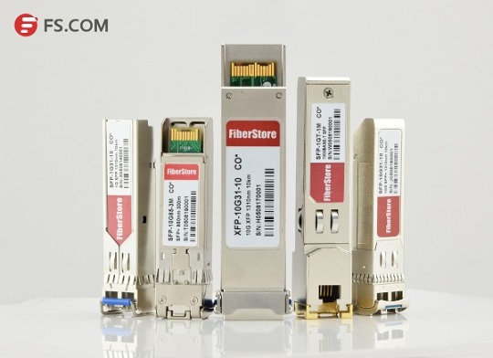
Сколько типов модулей вы знаете? Да, я знаю. Из FS.COM, я нахожу этот ответ. Волоконно-оптические трансиверы имеют полный спектр оптических SFP. FS.COM предоставляет различные типы оптических SFP, которые 100% совместимые с Cisco SFP, HP SFP, Juniper SFP, Netgear SFP, DELL SFP, CWDM SFP, SFP DWDM , BIDI SFP, 10G SFP и т. д. Существует так много типов трансивера SFP, я буду подробнее представлять несколько типов оптических SFP.
Первые типы оптических SFP: CWDM SFP
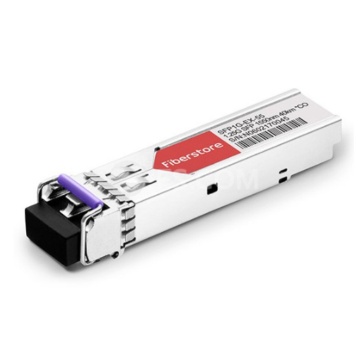
CWDM SFP (small form-factor pluggable) - это действительно компактный оптический модуль, используемый в оптических связях для телекоммуникационных и коммуникационных приложений на длине волны. CWDM SFP используются для соединения портов с оптической сетью, типичный CWDM SFP как Cisco CWDM SFP может поддерживать Gigabit Ethernet и Fibre Channel. Модули трансиверов CWDM SFP используют интерфейс оптический SFP для подключения оборудования и двойной волоконный интерфейс разъема LC PC для подключения к оптической сети. CWDM SFP модули могут быть найдены с различными типами передатчиков и приемников, что позволяет пользователям выбирать соответствующий трансивер для каждой линии связи для предлож��ния требуемого оптического диапазона по доступному оптическому волокну.
Второй тип оптических SFP: SFP DWDM
Плотное Мультиплексирование (с разделением) по Длинам Волн (DWDM) предлагают DWDM транспорт с значительно меньшей мощностью и стоимостью в стандартном упаковке оптических SFP. SFP DWDM доступен на всех длинах волн C/L-полосы длин волн на сетке ITU DWDM. В качестве многолинейных интерфейсов они поддерживают любой протокол от 100 Мбит/с до 4,25 Гбит/с. Модули отвечают требованиям стандарта IEEE802.3 Gigabit Ethernet и спецификациям ANSI Fibre Channel, они подходят для взаимосвязях в средах Gigabit Ethernet и Fibre Channel. SFP DWDM предназначен для приема DWDM SONET/SDH (с или без FEC) для 200 километровых соединений и трафика протокола Ethernet /Fibre Channel для 80 километровых соединений.
Третий тип оптических SFP: SFP 10G
Модули трансивера SFP 10G относятся к молулям 10G SFP Plus, кто-то знает, что SFP 10 представляет собой усовершенствованную версию оптического SFP, поддерживающую скорость передачи данных макс.до 10 Гбит/с. Было выпущено несколько стандартов для SFP 10G, 10GBase-SR подходит для многомодового оптического волокна OM3, соответствующего SFP plus рабочее расстояние до 300 метров, 10GBase-LR подходит для одномодового оптического волокна, соответствующий SFP plus рабочее расстояние 10 км, 10GBase-LRM подходит для FDDI многомодового волокна, SFP plus рабочее расстояние 220 метров.
Хотите узнать больше типов оптических SFP, посетите мой блог, я продолжаю обновлять информацию о волоконно-оптичеком модуле.
0 notes
Text
SFP 40 km VS. DWDM SFP: Which to Choose?
Small Form-factor Pluggable (SFP) is a compact, hot-pluggable transceiver used for both telecommunication and data communications applications. It is also called mini-GBIC for its smaller size, which is the upgraded version of GBIC transceiver. These 1Gb SFP modules are capable of supporting speeds up to 4.25 Gbps. And they are most often used for Fast Ethernet of Gigabit Ethernet applications. It interfaces a network device motherboard (for a switch, router, media converter or similar device) to a fiber optic or copper networking cable. SFP modules are commonly available in several different categories: 1000BASE-T SFP, 1000BASE-EX SFP, 1000BASE-SX SFP, 1000BASE-LX/LH SFP, 1000BASE-BX SFP, 1000BASE-ZX SFP, CWDM SFP and DWDM SFP. These modules support different distance according to the different Gigabit Ethernet standard. Today’s main subject will discuss SFP 40 km vs. DWDM SFP.
SFP 40 km
SFP 40 km transceiver is designed for highly reliable fiber optic network links up to 40 km. It is a cost effective transceiver designed to enable 1Gb for data center and core network applications. 1000BASE-EX SFP is the most popular SFP 40 km transceiver which runs on 1310nm wavelength lasers and achieves 40km link length. Except that, 1000BASE-BX BiDi SFP, 1000BASE-LH SFP and 1000BASE-LX SFP can also realize the transmission distance up to 40 km. The following will introduce these 1GbE SFP 40 km transceivers respectively.
1000BASE-EX SFP 40 km
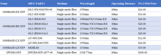
1000BASE-EX SFP transceiver module is designed to connect a Gigabit Ethernet port to a network and has dual LC/PC single mode connectors. It operates on standard single-mode fiber-optic link spans of up to 40 km in length. The SFP Ethernet module provides a dependable and cost-effective way to add, replace or upgrade the ports on switches, routers and other networking equipment. Cisco GLC-EX-SM1550-40 and Cisco GLC-EX-SMD are 1G single mode fiber SFP 40 km modules for 1000BASE-EX Gigabit Ethernet transmission. GLC-EX-SM1550-40 supports a 1550nm wavelength signaling, while GLC-EX-SMD supports a 1310nm wavelength signaling.
1000BASE-BX SFP 40 km
1000BASE-BX SFP is a kind of BiDi transceiver, which can be divided into 1000BASE-BX-D SFP and 1000BASE-BX-U SFP. These two SFP transceivers must be used in pairs to permit a bidirectional Gigabit Ethernet connection using a single strand of single mode fiber (SMF) cable. The 1000BASE-BX-D SFP operates at wavelengths of 1490nm TX/1310nm RX, and the 1000BASE-BX-U SFP operates at wavelengths of 1310nm TX/1490nm RX.
1000BASE-BX-D BiDi SFP 40 km
Cisco GLC-BX40-D-I and GLC-BX40-DA-I are pluggable fiber optical transceivers for Gigabit Ethernet 1000BASE-BX and Fiber Channel communications. They support link length of up to 40 km point to point on single mode fiber at 1Gbps bidirectional and use an LC connector. The GLC-BX40-D-I transceiver transmits a 1490nm channel and receives a 1310nm signal, whereas GLC-BX40-DA-I transmits at a 1550nm wavelength and receives a 1310nm signal.
1000BASE-BX-U BiDi SFP 40 km
Similar to 1000BASE-BX-D 40 km SFP , Cisco GLC-BX40-U-I and GLC-BX40-UA-I also support link length of up to 40 km point to point on single mode fiber at 1Gbps bidirectional and use an LC connector. The main difference is the wavelength: GLC-BX40-U-I transmits a 1310nm channel and receives a 1550nm signal, whereas GLC-BX40- UA-I transmits at a 1310nm wavelength and receives a 1490nm signal. A GLC-BX40-D-I or GLC-BX40-DA-I device connects to a GLC-BX40-U-I or GLC-BX40-UA-I device with a single strand of standard SMF with an operating transmission range up to 40 km.
1000BASE-LX SFP 40 km
1000BASE-LX is a standard specified in IEEE 802.3 Clause 38 which uses a long wavelength laser. The “LX” in 1000BASE-LX stands for long wavelength, indicating that this version of Gigabit Ethernet is intended for use with long-wavelength transmissions (1270 - 1355nm) over long cable runs of fiber optic cabling. Allied Telesis AT-SPLX40 and Allied Telesis AT-SPLX40/1550 are 1000BASE-LX SFP single-mode modules supports Gigabit Ethernet over single-mode cables at distances up to 40 km. AT-SPLX40 operates over a wavelength of 1310nm for 40 km, whereas AT-SPLX40/1550 operates over a wavelength of 1550nm.
1000BASE-LH SFP 40 km
Unlike 1000BASE-LX, 1000BASE-LH is just a term widely used by many vendors. Long Haul (LH) denotes longer distances, so 1000BASE-LH SFP modules operate at a distance up to 70 km over single mode fiber. Cisco Linksys MGBLH1 is a easy-to-install modules that provide a simple way to add fiber connectivity or to add an extra Gigabit Ethernet port to switches. The MGE transceiver can support distances up to 40 km over single-mode fiber at a 1310nm wavelength.
DWDM SFP
DWDM SFP transceivers are used as part of a DWDM optical network to provide high-capacity bandwidth across an optical fiber network, which is a high performance, cost effective module for serial optical data communication applications up to 4.25Gb/s. DWDM transceiver uses different wavelengths to multiplex several optical signal onto a single fiber, without requiring any power to operate. There are 32 fixed-wavelength DWDM SFPs that support the International Telecommunications Union (ITU) 100-GHz wavelength grid. The DWDM SFP can be also used in DWDM SONET/SDH (with or without FEC), but for longer transmission distance like 200 km links and Ethernet/Fibre Channel protocol traffic for 80 km links. Cisco C61 DWDM-SFP-2877-40 is a 1000BASE-DWDM SFP 40km transceiver, which is designed to support distance up to 40 km over single-mode fiber and operate at a 1528.77nm DWDM wavelength (Channel 61) as specified by the ITU-T.
SFP 40 km VS. DWDM SFP
Transmission Medium
Generally, the standard SFP 40 km transceivers transmit through the single mode fiber, while DWDM SFP carries signals onto a single optical fiber to achieve maximum distances by using different wavelengths of laser light. So the DWDM SFP transceivers do not require any power to operate.
Wavelength
The standard SFP 40 km transceivers support distances up to 40 km over single-mode fiber at a 1310nm/1550nm wavelength. (the BiDi SFP has 1490nm/1550nm TX & 1310nm RX or 1310nm TX & 1490nm/1550nm RX ). However, DWDM SFP operates at a nominal DWDM wavelength from 1528.38 to 1563.86nm onto a single- mode fiber. Among them, 40 km DWDM SFP operates at a 1528.77nm DWDM wavelength (Channel 61).
Application
DWDM SFP is used in DWDM SONET/SDH, Gigabit Ethernet and Fibre Channel applications. These modules support operation at 100Ghz channel. The actual SFP transceiver offers a transparent optical data transmission of different protocols via single mode fiber. And for back-to-back connectivity, a 5-dB inline optical attenuator should be inserted between the fiber optic cable and the receiving port on the SFP at each end of the link.
Price
DWDM provides ultimate scalability and reach for fiber networks. Boosted by Erbium Doped-Fiber Amplifiers (EDFAs) - a sort of performance enhancer for high-speed communications, DWDM systems can work over thousands of kilometers. Most commonly, DWDM SFP is much more expensive than the standard SFP. You can see the price more clearly in the following cable.
Conclusion
1000BASE SFP transceiver is the most commonly used component for Gigabit Ethernet application. With so many types available in the market, careful notice should be given to the range of differences, both in distance and price of multimode and single-mode fiber optics. Through SFP 40 km vs. DWDM SFP, if you are looking for SFP modules over long distance and with better scalability, DWDM SFP module is the ideal choice.
Related Article: SFP Transceiver: To Be or Not To Be?
0 notes
Photo

https://www.cbo-it.de/de/produkte/blueoptics/transceiver/sfpplus.html
The CWDM transceivers are working in a specific optical frequency ranges defined by the ITU-T. In 2002 the ITU standardized a channel spacing grid for use with CWDM (ITU-T G.694.2), using the wavelengths from 1270nm through
1610nm with a channel spacing of 20nm.
0 notes
Text
Understanding the Use of Optical Fused Coupler, MUX & DEMUX WDM
In today’s high tech world, there is a desperate need for bandwidth. The development of WDM (wavelength division multiplexing) technology has greatly helped us to expand the network capacity over a single fiber. A fiber optic coupler is a device used in fiber optic systems with input fibers (single or more) and output fibers (single or more). It is different from WDM devices.
The main benefits of Optical fused couplers are as follows:-
Combining: This Fiber Optic Couplers combine two signals and yield single output.
Splitting: The Splitters supply two outputs by using the single optical signal.
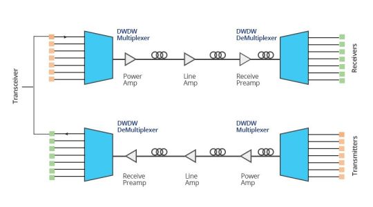
On the other hand, WDM multiplexer and demultiplexer divide the different wavelength fiber light into different channels. WDM is further divided into CWDM (coarse wavelength division multiplexing) and DWDM (dense wavelength division multiplexing). Generally, the WDM systems operate on 9µm single-mode fiber optical cables although it is not necessary.
If we specifically talk about the CWDM method, CWDM multiplexes multiple optical carrier signals on a single optical fiber. It uses different wavelengths/colors of laser light combined in a MUX in order to carry different signals. Mux/DeMux is one of the most important components of CWDM systems.
The LGX CWDM Mux and DeMux module comes with a 8 Channel (dual fiber) with 1U 19 Rack Mount Box that utilizes thin film coating technology and proprietary design of non-flux metal bonding micro optics packaging. It has been designed to provide optical networking support over a grid of CWDM optical wavelengths in high-speed Fibre Channel and Ethernet communication for metropolitan area networks (MAN).
The optical component is easy to operate with a reliable low-maintenance design. The MUX is passive and it does not use power supplies or electronics. It is capable of multiplexing and demultiplexing ITU-T G.694.2 wavelengths up to 8 channels in increments of 20nm from 1270 nm to 1610 nm. “ITU” specifies the exact center of 8CH CWDM Mux and Demux dual fiber 1U 19 Rack Mount Box wavelength such as 1531nm, 1591nm, 1611nm, etc.
The 8 Channel CWDM Mux and Demux dual fiber 1U 19 Rack Mount Box are protocol and rate transparent. They allow different services up to 10Gbps transported across the same fiber link. It works seamlessly with transceivers to optimize the link length, signal integrity, and overall network cost. It can be incorporated into a single rack-mount solution for a better design, power, and space efficiency.
As per the working principle, MUX and DEMUX can be used in various fields, such as communication systems, computer memories, telephone networks, etc. It is a cost saving method of connecting a multiplexer and a demultiplexer together over a single channel.
How to get the Optical Fused Couplers, Mux and DeMux WDM?
There are several leading companies in market that are considered masters at the designing and manufacturing of optical passive components for fiber laser, fiber sensor, and fiber optic telecommunication applications. One can contact these companies to avail high quality opticalcouplers, Mux and DeMux at affordable rates.
Contact a supplier today and get them.
0 notes
Text
CWDM Network: Technology Overview and Common Applications
Fiber exhaust is an inevitable problem constantly faced by carriers since the demand for higher speed bandwidth never ceases. The ever-improving wavelength division multiplexing (WDM) technology nowadays is increasingly used to boost network capacity, enabling carriers to deliver more services over their existing fiber infrastructure. CWDM, as one form of the mature WDM technologies, is a perfect fit for access networks and metro/regional networks. This article addresses the CWDM fundamentals and its common applications, and how CWDM helps to maximize network capacity effectively.
CWDM Technology at a Glance
Coarse wavelength division multiplexing (CWDM) came into prominence as a cost-effective alternative to maximize network capacity in the access, metro and regional network segments. It gains in more popularity in area with a relatively moderate traffic growth due to its simple deployment and low cost. ITU-T G.694.2 defines 18 wavelengths for CWDM transport ranging from 1270 to 1610 nm, spaced at 20 nm apart. But 8 wavelength in the 1470-1610nm band is mostly used since there exist high attenuation in the 1270-1450 nm band. This technology shines out in access network deployments by obtaining the advantages of flexible add-drop capacity and network design simplicity.

Common Applications of CWDM
After going through the basics of CWDM technology, this section will further explain its common applications. CWDM is primarily deployed in two areas: metropolitan and access networks. Let’s see how they could benefit from applying it.
Fiber Exhaust Relief
Fiber exhaust appears to be a severe problem that carriers endeavor to solve, especially for some metropolitan networks where data traffic increases continuously. Adding CWDM to the original optical network presents a cost-efficient and simple approach to this problem. In this case, carriers can add new services over a existing single optical fiber, while not interrupting service for existing customers. This solution is ideally suited for carriers that desires to increase the already installed network capacity without new fiber construction.

Enterprise LAN and SAN Connection
When interconnecting geographically dispersed Local Area Networks (LANs) and Storage Area Networks (SANs), CWDM rings and point-to-point links offer an optimum option. It is beneficial to integrate multiple Gigabit Ethernet, 10 Gigabit Ethernet and Fiber Channel links over a single fiber for CWDM point-to-point applications or for ring applications.

Adoption in Metro Networks With Lower Cost
4 channel CWDM system offers an ideal solution for smaller metro/regional markets which demand for moderate traffic growth. This configuration can expand the available capacity four times over an existing network, enabling less deployment cost than the commonly adopted 8 channel system. Meanwhile, the scalability of this 4 channel system also allows carriers to upgrade to 8 channel systems when the need occurs.
Central Office to Customer Premise Interconnection
Coarse WDM system is also well-fitted for metro-access applications such as Fiber to the Building (FTTB). Let’s take the most widely used 8 channel CWDM network for example, it is capable of delivering 8 independent wavelength services from the Central Office (CO) to multiple business offices located in the same building.

Combining With PON
Passive Optical Network (PON) is a point-to-multipoint optical network to deliver bandwidth to the last mile. It is cost-effective because it uses passive devices (splitters for example) instead of expensive active electronics. The issue exists in PON is that the amount of bandwidth they can support is rather limited. Since CWDM serves to multiple bandwidth, when combining it with PON, each additional lambda becomes a virtual point-to-point connection from a central office to an end user. If one end user in the original PON deployment needs his own fiber, adding CWDM to the PON fiber creates a virtual fiber for that user. Once the traffic is switched to the assigned lambda, the bandwidth taken from the PON is now available for other end users, so the access system can maximize fiber efficiency.
Conclusion
CWDM has clearly become the preferred method for increasing the bandwidth of metro/regional and optical access networks quickly, simply and at lowest cost. And it has proven to be sufficiently robust and reliable for upgrading the optical network to accommodate future growth. Hope this article could help to get a better understanding of coarse WDM technology.
Source: http://www.fiber-optic-solutions.com/cwdm-technology-common-applications.html
0 notes
Text
Cwdm-sfp-1550 Cisco Cwdm 1550nm Sfp Gigabit Ethernet And 1g-2g Fc Transceiver Module
CWDM-SFP-1550
CWDM-SFP-1550 Cisco CWDM 1550nm SFP Gigabit Ethernet and 1G/2G FC Transceiver Module.
General Information Manufacturer Cisco Systems, Inc Manufacturer Part Number CWDM-SFP-1550 Manufacturer Website Address http://www.cisco.com Brand Name Cisco Product Name CWDM 1550-nm SFP Product Type SFP Technical Information Application/Usage Data Networking Interfaces/Ports Interfaces/Ports 1 x 1000Base-X Interfaces/Ports Details 1 x LC Duplex 1000Base-X Media Performance Connectivity Media Optical Fiber 1000Base-X Data Transfer Rate 2.12 Gbps Fibre Channel Full-duplex Data Transfer Rate 1.25 Gbps Gigabit Ethernet Full-duplex Miscellaneous Additional Information- Spare Product Center wavelength is 1550nm Color: Yellow Compliant with the ITU-T G.694.2 CWDM grid Compatible with Fibre Channel Draft Physical Interface Specification (FC-PI 10.0) Fibre Channel 1.06 and 2.12 Gbps full-duplex links with an optical link budget of 28 dB Compatibility- Catalyst 2900 series Catalyst 2950 series Catalyst 2960 series Catalyst 3560 series Catalyst 3750 series Catalyst 4500 series Catalyst 4900 series Catalyst 6500 series Cisco 7300 series Router Cisco 10700 Internet Router MDS 9000
Click to buy: Cwdm-sfp-1550 Cisco Cwdm 1550nm Sfp Gigabit Ethernet And 1g-2g Fc Transceiver Module from Mac Palace Products Feed https://ift.tt/2EbMyVz
0 notes