#Data Transmission PCB Card
Explore tagged Tumblr posts
Visit Tumblr Blog
Explore Tumblr blogs with no restrictions, modern design and the best experience.
Last Seen Tumblr Blogs


Fun Fact
If you dial 1-866-584-6757, you can leave an audio post for your followers.
Text
Liebherr PCB Card 925086914 0002555 0601004 | High-Quality Control PCB Board | Ram Automations
Enhance your machinery’s performance with the Liebherr PCB Card 925086914 0002555 0601004, available now at Ram Automations. This high-quality Printed Circuit Board (PCB) offers exceptional reliability, precision engineering, and durability for a wide range of industrial and marine applications.
Designed for maximum performance and efficiency, this Liebherr PCB Card ensures seamless integration with complex control systems, making it ideal for critical automation environments and high-demand applications.
🛒 Buy Now from Ram Automations 👉 https://ramautomations.com/products/pcb-card-925086914-0002555-0601004-liebherr-new
🌐 Explore 1000+ Genuine Automation Components 👉 https://ramautomations.com
🧩 Product Specifications
• 🔹 Brand: Liebherr • 🔹 Model: 925086914 / 0002555 / 0601004 • 🔹 Type: PCB Card • 🔹 Category: PCB Card / Industrial Electronics / Automation PCB • 🔹 Application: Industrial Automation, Marine Systems, Control Panels, Process Systems
✅ Key Features
✔️ Precision-engineered PCB for reliable performance ✔️ Seamless integration with industrial systems ✔️ High-quality materials and craftsmanship ✔️ Essential for complex machinery and automation units ✔️ Ideal for industrial, marine, and manufacturing environments
💡 Typical Applications
• Marine Electronic Control Systems • Industrial Automation Panels • SCADA and HMI System Boards • Heavy Equipment Automation • Process Automation Systems • Robotics Control Panels • Industrial Machinery Systems
🌟 Why Choose Ram Automations?
✅ 100% Genuine Products Only ✅ Best Prices with Worldwide Delivery ✅ Trusted Industrial Automation Supplier ✅ Large Inventory of Hard-to-Find Components
🛍️ Visit Us: https://ramautomations.com
In This Video You Will Discover:
🔎 Close-up View of Liebherr PCB Card 🔧 How It Integrates with Complex Systems 💡 Importance of High-Quality PCBs in Industrial Automation 🌐 Why Ram Automations is the Go-To Source for Industrial Parts
📣 Get Involved!
🔔 Subscribe for Automation & Electronics Updates 👍 Like to Show Support for Quality Electronics 💬 Comment Your Queries — We’re Happy to Help! 🛒 Visit our Online Store: https://ramautomations.com
#Liebherr PCB Card#PCB Card for Automation#Industrial PCB Card#Automation PCB Card#Marine Control PCB#Automation System Board#Ram Automations#Control Panel PCB Card#Process Control PCB#Marine Automation Electronics#Industrial Electronic PCB#Automation Equipment PCB Card#Marine Systems PCB Card#Factory Automation Parts#Robotics Control Panel Card#Data Transmission PCB Card#PLC Control PCB Card#High Quality PCB Card#SCADA System PCB Card#Electronic Connectivity PCB Board
1 note
·
View note
Text
i just did a few reaction time tests using two different gaming mice (one being a cheap wired mouse, the other being an entry level wireless mouse from a known brand) and got surprisingly different results. the really surprising thing is that the wired mouse is not, in fact, the fastest.
i did 4 tests of 5 for each mouse (randomly switching mouse to try and mitigate getting better at it after doing the test a bunch of times) and the best of all, with an average reaction of 223.5ms was the wireless mouse over 2.4GHz. the surprising thing is that in this case and only this case (wireless 2.4) did i get any below 200ms results, going as low as 150 once.
the second fastest was the crappy wired mouse, with an average of 244.5ms of reaction time, which is +21ms on average.
and the third and last was the wireless mouse over bluetooth, averaging at 271.5ms, 48ms more than the 2.4GHz score.
given the scenario (mouse on a desk, with a computer located under the desk, with a wireless pcie card on the bottom of the computer with two antennas pointed upwards, and the wireless 2.4GHz dongle placed on the top USB ports) i'm gonna say that a 48ms difference for bluetooth and 2.4GHz is not usual, and perhaps with a better setup, like a desk top desktop (haha, get it?) or a laptop, the difference would be minimised (but not eliminated). as for the difference between the 2.4GHz and the wired, i think it can be clearly attributed to the poor quality of the wired mouse. but what in particular, i have two theories :
1 : the mouse has very low quality internals that do not allow for a fast transmission of signals, whether it is in it pcb or in the cable or whatever.
2. the mechanical parts of the mouse (the actual buttons) are of a terrible quality, require perhaps more force to push the button, adding a delay to the press.
it could be a bit of both, but i do believe that the wireless mouse clicks just feel better.
i think in order to get any scientifically acceptable result, i would need to get a much higher volume of data, try it with different people, different mice, different computers.
#is this what you may call a pilot study?#is it proof that i need aditional funding to conduct a real study#that would allow me to draw a conclusion?
3 notes
·
View notes
Text
Everything You Need to Know About Board to Board Connectors in PCB Equipments

When developing PCB systems, recognizing board to board connectors is vital for guaranteeing reliable communication and power transmission. With different kinds offered, selecting the right port includes more than simply matching requirements. You'll need to take into account elements like pitch, stack elevation, and electric ratings to preserve signal honesty. As you browse these intricacies, the relevance of trusted resource and correct execution becomes clear. What other components should you keep in mind to optimize your styles?
Kinds of Board to Board Connectors
Board-to-board connectors play an important duty in helping with interaction and power transfer in between different published circuit card (PCBs) within digital tools. You'll experience numerous kinds of pcb board to board connector, each customized for details applications. For example, conventional adapters offer dependable connections for basic functions, while express board to board connectors accommodate applications calling for fast data transmission.
Capabilities and Functions
Understanding the performances and apps of board-to-board adapters is important for optimizing digital styles. These connectors enable reliable affiliation in between several PCB layers, enhancing signal honesty and minimizing setting up intricacy. When selecting a pcb board to board adapter, consider factors like piling elevation, pitch, and positioning. Apps cover customer electronics, automobile systems, and industrial hands free operation, where reputable links are crucial.
Secret Factors To Consider for Selection

When choose high speed board to board connector, you ought to think about numerous important aspects to guarantee peak performance in your PCB design. Initially, assess the port's pitch and stack height to identify compatibility with your design. Next off, analyze the electrical present ranking and call resistance, which straight influence signal honesty. Wish to partner along with a trusted https://lxw-conn.com/ that delivers both precision and toughness? Go here to get going.
Best Practices for Application
To ensure peak performance throughout execution, you need to prioritize correct positioning and placement of board-to-board adapters on your PCB. Misalignment can cause bad lxw connectivity, leading to signal loss or electrical failures. Identify that the ports are placed within the style's defined tolerances to help with perfect breeding. Make use of automated setting up strategies when suitable to enhance precision.
Final Thought
In the grand tapestry of PCB layout, selecting the best board to board connector is akin to picking the ideal connection for a job meeting crucial yet frequently overlooked. Sure, you might slap any kind of port on and expect the most effective, but that's like putting on flip-flops to a board meeting. By carefully taking into consideration kinds, capabilities, and best methods, you'll not just stay clear of technical artificial pas however additionally boost your layouts to a level of professionalism and trust that also your mother would certainly boast of.
0 notes
Text
Price: [price_with_discount] (as of [price_update_date] - Details) [ad_1] Mini Cool Edge IO. The 0.60mm pitch connector come with a slim form factor design, capable of transmitting high-speed signal up to 64G PAM4/PCIe Gen 4/PCIe Gen 5/PCIe Gen 6, and allowing much greater signal path lengths while maintaining SI performance when compared to conventional pcb routing methods. Mini Cool Edge IO not only provides a SI performance ready signal transmission but also a new way of system design that is cost-effective, highly modular, scalable, and extremely easy to repair. 0.60mm pitch, vertical and right angle configurations;Slim form factor for compact data center system designs Up to 64Gb/s PAM4, PCIe Gen 4, PCIe Gen 5, PCIe Gen 6, over 1.0 meter transmission distance;Extends transmission range far more over the conventional PCB routes Supports both cable and card edge applications with one identical connector;Provides flexibility in system design to meet highly modular, scalable and easy-to-repair requirements Optional for 92Ω (G42 series), 85Ω (G97/GH01X series) and 95Ω (G98 series) impedance and various pin number options - meeting PCIe/NVMe/SAS/SFP(+)/QSFP specifications;Saves system material cost, engineering and certification expenses with high succession of system design [ad_2]
0 notes
Text
The Terasaki Electric ECA-105 Multiplex WTM Sender PCB Card is a reliable and efficient component designed for precise signal processing in industrial and marine automation. Built with advanced technology, it ensures accurate data transmission and seamless integration with control units. Its durable construction makes it ideal for demanding environments, providing consistent performance and longevity. Easy to install and maintain, this PCB card enhances the efficiency of automation systems while reducing downtime. Choose the ECA-105 PCB card for top-tier performance and reliability. Explore this and more premium automation products at Auto2mation, your trusted source for industrial solutions.
#auto2mation#industrial equipment#industrial automation#marine spare parts#industrial and marine automation#industrial and marine automation equipment#industrial automation equipment#industrial spare parts#marine automation#automation#pcb#terasaki
0 notes
Text
ASRock Z890 Taichi OCF: A Milestone In Memory Overclocking

By overclocking its memory to an unprecedented DDR5-12527MHz, the ASRock Z890 Taichi OCF breaks the world record!
This accomplishment demonstrates the Z890 Taichi OCF‘s remarkable performance and dependability in harsh environments, enhancing its standing as the best option for enthusiasts and expert overclockers. The motherboard’s 10-layer PCB, server-grade ultra-low-loss material, and ASRock’s patent-pending Memory OC Shield, which lowers EMI noise, provide unparalleled stability and performance for overclocking. It can handle memory frequencies up to DDR5-12527MHz.
ASRock Z890 Taichi OCF Overview
Unleashing Extreme Performance
Image Credit To ASRock
This motherboard, made for dedicated overclockers, is designed to use LN2 cooling to push your system to its maximum potential. Gain the greatest advantage in smashing records and optimizing hardware capabilities by experiencing previously unheard-of performance and stability in harsh environments.
Extreme Memory Overclocking
Based on the design principle of “built for stable and reliable,” ASRock doesn’t skimp on any aspects. This motherboard is constructed from premium materials, and by turning on the pre-tested profiles, enthusiasts may benefit from the increase in DDR5 memory overclocking capability. Verify that the RAM modules support AMD EXPO and Intel XMP, and that overclocking is inexpensive, fulfilling, and completely painless.
Memory overclocking has some hazards and might compromise the stability of your system. Please be aware that overclocking is something you should undertake at your own risk and cost. Support for EXPO/XMP profiles may change depending on the motherboard type, RAM modules, and system setup. The completed support list may be found in Memory QVL.
Top-tier hardware specifications, a sturdy power design, Thunderbolt 4 Type-C, and DIY-friendly functionality are all aspects of the Z890 Taichi OCF Taiichi series flagship motherboard. With its opulent design and potent performance, it is designed for high-end gamers.
Overclock Toolkit
OC Buttons Taichi OCF’s OC Buttons provide hardware-level controls to help with severe overclocking and improve your overclocking experience.
+/- Rapid OC Buttons: These buttons let users change the OC frequency in Rapid OC fast and simply.
Buttons for OC Profiles 1, 2, and 3: To load the preset OC Profiles 1, 2, or 3 rapidly, use the OC Profile Buttons in Rapid OC.
LN2 Mode Switch: When using liquid nitrogen for high overclocking, the LN2 mode helps to remove the cold-boot bug problems in CPUs.
Slow Mode Switch: To stabilize the system for extreme overclocking, use Slow Mode to operate the processor at its lowest frequency.
Retry Button: When a forced shutdown is required, restart the system right away.
To boot using the BIOS’s default settings, use the “Safe Boot” button.
DIY Friendly Design
Graphics Card EZ Release
To meet customer demands, ASRock changed the PCIe slot installation process, making it simple to install and remove the graphics card.
Professional Overclocking
CPU Heater Header
It is designed to improve overclocking results by preventing CPU SoC Tile freezing during LN2 intense overclocking with up to 42W of heating power by duty. It is equipped with a heater header that makes it simple to connect ceramic heating pads into the CPU socket.
Dual Thunderbolt 4 Type-C
It links a variety of devices with a single Thunderbolt 4 connection and allows for lightning-fast data transmission up to 40Gbps.
Premium PCB Solution
Server-Grade Ultra Low-Loss PCB
By enhancing signal integrity, the server-grade ultra low-loss PCB enables the motherboard to support PCIe 5.0 for both graphics cards and M.2 SSDs. It also enhances memory OC capability to provide the highest possible memory performance.
Deluxe 6xM.2 Sockets
Supports a maximum of six NVMe M.2 SSDs, one of which can support the most recent PCI Express 5.0 standard.
22+1+2+1+1 Power Phase, 110A SPS
The most recent SPS (Smart Power Stage) technology is included into the Dr.MOS design. It is designed to monitor the temperature and current of each phase, allowing for more efficient power delivery to the CPU, improving performance and OC potential.
Ultra-Fast Networking
802.11be Wi-Fi 7
Wi-Fi 7 provides multi-link operation, reduced latency, and increased data speed. The VR/AR experience is made more immersive and linked by these characteristics, which guarantee a seamless and real-time interactive experience.
Dual USB 3.2 Gen2x2 Type-C (1 Rear, 1 Front)
Reversible USB 3.2 Gen2x2 Type-C can connect either way and transport data at 20 Gbps, twice as fast as the previous iteration.
BIOS Flashback
With a single click, get the most convenient BIOS flashing. With just a USB and power supply, users may effortlessly get the most recent BIOS support; no CPU, RAM, or other parts are needed.
Read more on govindhtech.com
#ASRockZ890TaichiOCF#Milestone#ASRock#WiFi7#MemoryOverclocking#DDR5memory#M2SSDs#Gen2x2#PremiumPCBSolution#CPUHeaterHeader#technology#technews#news#govindhtech
0 notes
Text
Enhancing Industrial Automation with the Simac C.S.I. 4969/09 PCB Card
In the realm of industrial automation, the efficient operation of machinery and control systems relies heavily on the integration and functionality of various electronic components. Among these, the Simac C.S.I. 4969/09 PCB card stands out as a critical element for improving automation processes. This article delves into the features, advantages, and applications of the Simac C.S.I. 4969/09 PCB card, highlighting its role in modern industrial environments.
Overview of the Simac C.S.I. 4969/09 PCB Card:
The Simac C.S.I. 4969/09 PCB card is a high-performance printed circuit board designed for use in industrial automation systems. Known for its robustness and versatility, the C.S.I. 4969/09 integrates seamlessly into a variety of automation setups, providing essential functions such as signal processing, communication interfacing, and control logic. Its design reflects the demands of industrial environments, ensuring reliable performance under rigorous conditions.
Key Features:
Advanced Signal Processing: The C.S.I. 4969/09 is equipped with advanced signal processing capabilities that enhance the accuracy and reliability of data transmission. This feature is crucial for applications where precise control and monitoring of industrial processes are required.
Robust Construction: The PCB card is built to withstand the harsh conditions typical of industrial environments. Its durable construction ensures longevity and reliable operation, even in settings with high temperatures, electrical noise, and mechanical vibrations.
Versatile Integration: Designed for flexibility, the C.S.I. 4969/09 can be integrated into a wide range of automation systems. It supports various communication protocols and interfaces, making it suitable for diverse applications across different industries.
Enhanced Connectivity: The card provides robust connectivity options, facilitating seamless communication between different components of an automation system. This ensures smooth data exchange and coordination between legacy and modern equipment.
Ease of Installation: The C.S.I. 4969/09 is designed for user-friendly installation. Its straightforward mounting and connection processes help minimize setup time and reduce the risk of errors during installation.
Low Maintenance Requirements: With minimal maintenance needs, the C.S.I. 4969/09 allows for uninterrupted operation of industrial systems. Its reliable performance reduces the frequency of maintenance checks and associated downtime.
Advantages of Using the Simac C.S.I. 4969/09 PCB Card
Improved Operational Efficiency: By enhancing signal processing and communication capabilities, the C.S.I. 4969/09 contributes to overall operational efficiency. Its ability to handle complex data and commands ensures that industrial processes run smoothly and efficiently.
Increased System Compatibility: The versatility of the C.S.I. 4969/09 allows for easy integration with both older and newer automation systems. This compatibility is essential for businesses looking to modernize their operations without discarding existing equipment.
Enhanced Reliability: The card’s robust construction and reliable performance enhance the dependability of industrial automation systems. Reduced risk of failure translates to improved system uptime and productivity.
Cost-Effective Solution: The C.S.I. 4969/09 offers a cost-effective solution for upgrading and maintaining industrial automation systems. Its ability to interface with various equipment helps businesses avoid the costs associated with complete system replacements.
Scalability: The card supports scalable automation solutions, allowing businesses to expand and upgrade their systems as needed. This flexibility ensures that the automation infrastructure can grow in line with operational demands.
Applications in Industrial Automation
The Simac C.S.I. 4969/09 PCB card is suitable for a wide range of applications in industrial automation:
Manufacturing Control Systems: In manufacturing environments, the card can be used to control machinery and processes, ensuring precise operation and coordination of equipment.
Process Monitoring: The card’s advanced signal processing capabilities make it ideal for monitoring industrial processes. It enables real-time data collection and analysis, facilitating prompt response to operational changes.
Remote Monitoring and Control: The C.S.I. 4969/09 can be integrated into remote monitoring systems, allowing operators to oversee and control equipment from distant locations.
Integration with SCADA Systems: The card supports integration with Supervisory Control and Data Acquisition (SCADA) systems, providing a critical link between field devices and central control stations.
Legacy System Upgrades: For businesses with existing analog or older digital systems, the C.S.I. 4969/09 offers a means to upgrade and integrate these systems with modern automation technologies.
Conclusion:
The Simac C.S.I. 4969/09 PCB card is a vital component for enhancing industrial automation systems. Its advanced features, robust construction, and versatile integration capabilities make it a valuable asset for businesses looking to optimize their automation processes. By improving signal processing, connectivity, and system compatibility, the C.S.I. 4969/09 helps ensure efficient and reliable operation in demanding industrial environments. As industries continue to evolve and embrace new technologies, the C.S.I. 4969/09 stands out as a key player in bridging the gap between legacy systems and modern automation solutions.
0 notes
Text
Board-to-Board Connectors Market Future Trends and Scope Analysis Forecast 2024-2033
Market Definition
Board-to-board connectors, also known as interconnects, are electronic components used to connect two or more printed circuit boards (PCBs) together. They provide a secure and reliable connection between PCBs, allowing for the transfer of signals, power, and data between them.
There are various types of board-to-board connectors, such as through-hole, surface mount, and card-edge connectors. Through-hole connectors have pins that pass through holes in the PCB and are soldered to the board, while surface mount connectors have flat contacts that are soldered directly to the surface of the PCB. Card-edge connectors, on the other hand, have a series of contacts that are designed to mate with a card or another PCB.
Market Outlook
Board-to-board connectors, also known as interconnects, play a critical role in connecting different printed circuit boards (PCBs) within electronic devices. These connectors are used to transfer power, signals, and data between PCBs, enabling the seamless functioning of electronic devices. With the rapid advancements in technology and the increasing demand for smaller, faster, and more efficient electronic devices, board-to-board connectors have undergone significant changes and innovations. In this article, we will discuss the key trends in board-to-board connector technology.
1. Miniaturization and High-Density Connectors: One of the most prominent trends in board-to-board connectors is miniaturization. As electronic devices become smaller and more compact, the need for smaller and high-density connectors has increased. Manufacturers are developing connectors that take up less space on the PCB while maintaining high signal integrity and reliability. This trend has been driven by the demand for smaller and thinner devices such as smartphones, tablets, and wearables.
2. High-Speed Data Transfer: With the increasing use of high-speed data transfer technologies like USB, HDMI, and Thunderbolt, there is a growing demand for board-to-board connectors that can support high data transfer rates. These connectors must also be able to maintain signal integrity and minimize losses over long distances. To meet this demand, manufacturers are developing connectors with improved shielding, reduced crosstalk, and higher bandwidth capabilities.
3. Flexibility and Modularity: Another trend in board-to-board connectors is the development of flexible and modular connectors. These connectors allow for easy customization and reconfiguration of PCBs, making them ideal for use in complex and constantly evolving electronic devices. Flexible connectors also offer improved shock and vibration resistance, making them suitable for use in harsh environments.
4. Robust and Reliable Connectors: As electronic devices become more pervasive in various industries, the demand for robust and reliable connectors has increased. Manufacturers are developing connectors with improved durability, resistance to extreme temperatures, and resistance to shock and vibration. These connectors are also designed to withstand harsh environmental conditions, making them suitable for use in industrial, automotive, and military applications.
Board-to-board connectors are essential components used in the electronics industry for connecting printed circuit boards (PCBs) together. These connectors are designed to provide a secure and reliable connection between PCBs, allowing for the transmission of signals, power, and data between different boards. The global board-to-board connectors market is expected to grow at a significant rate in the coming years, driven by several key factors.
1. Increasing Demand for Electronic Devices: The growing demand for electronic devices, such as smartphones, tablets, laptops, and other consumer electronics, is a major driver of the board-to-board connectors market. With the increasing adoption of these devices, there is a need for smaller and more efficient connectors to save space on PCBs and improve the overall performance of the device.
2. Advancements in Technology: Technological advancements in the electronics industry have led to the development of complex and miniaturized electronic devices. This has increased the demand for smaller and more compact connectors, which can be achieved through the use of board-to-board connectors. These connectors offer a higher level of integration and can withstand high-speed data transmission, making them ideal for use in advanced electronic devices.
3. Growing Automotive Industry: The automotive industry is a significant end-user of board-to-board connectors. With the increasing adoption of advanced technologies in vehicles, such as infotainment systems, driver assistance systems, and electric vehicles, the demand for board-to-board connectors is also increasing. These connectors are used in the electronic control units (ECUs) and other electronic components of vehicles, making them essential for the proper functioning of the vehicle.
To Know More: https://www.globalinsightservices.com/reports/board-to-board-connectors-market//?utm_id=1014
Research Objectives
Estimates and forecast the overall market size for the total market, across product, service type, type, end-user, and region
Detailed information and key takeaways on qualitative and quantitative trends, dynamics, business framework, competitive landscape, and company profiling
Identify factors influencing market growth and challenges, opportunities, drivers and restraints
Identify factors that could limit company participation in identified international markets to help properly calibrate market share expectations and growth rates
Trace and evaluate key development strategies like acquisitions, product launches, mergers, collaborations, business expansions, agreements, partnerships, and R&D activities
Thoroughly analyze smaller market segments strategically, focusing on their potential, individual patterns of growth, and impact on the overall market
To thoroughly outline the competitive landscape within the market, including an assessment of business and corporate strategies, aimed at monitoring and dissecting competitive advancements.
Identify the primary market participants, based on their business objectives, regional footprint, product offerings, and strategic initiatives
Request Sample: https://www.globalinsightservices.com/request-sample/GIS26871/?utm_id=1014
Market Segmentation
The Board-to-Board Connectors market has been segmented into Type, Application, Pitch Size, and Region. Based on the Type, the Board-to-Board Connectors market is Segmented into Consumer Electronics, Automotive, and Industrial. On the basis of Application, the market is segmented into Consumer Electronics, Automotive, and Industrial. Based on Pitch Size, the market is bifurcated into Fine Pitch Connectors and Coarse Pitch Connectors. Region-wise, the market is analyzed across North America, Europe, Asia Pacific, and the Rest of the World.
Request Customization@ https://www.globalinsightservices.com/request-customization/GIS26871/?utm_id=1014
Major Players
Some of the key players of Board-to-Board Connectors market are TE Connectivity (Switzerland), Molex (Koch Industries) (United States), Hirose Electric Co., Ltd. (Japan), JAE Electronics, Inc. (Japan), Samtec, Inc. (United States), Amphenol Corporation (United States), Kyocera Corporation (Japan), Yamaichi Electronics Co., Ltd. (Germany), ERNI Electronics GmbH (Switzerland), and HARTING Technology Group (Germany).
Request Discounted Pricing@ https://www.globalinsightservices.com/request-special-pricing/GIS26871/?utm_id=1014
Research Scope
Scope – Highlights, Trends, Insights. Attractiveness, Forecast
Market Sizing – Product Type, End User, Offering Type, Technology, Region, Country, Others
Market Dynamics – Market Segmentation, Demand and Supply, Bargaining Power of Buyers and Sellers, Drivers, Restraints, Opportunities, Threat Analysis, Impact Analysis, Porters 5 Forces, Ansoff Analysis, Supply Chain
Business Framework – Case Studies, Regulatory Landscape, Pricing, Policies and Regulations, New Product Launches. M&As, Recent Developments
Competitive Landscape – Market Share Analysis, Market Leaders, Emerging Players, Vendor Benchmarking, Developmental Strategy Benchmarking, PESTLE Analysis, Value Chain Analysis
Company Profiles – Overview, Business Segments, Business Performance, Product Offering, Key Developmental Strategies, SWOT Analysis
Buy your copy here: https://www.globalinsightservices.com/checkout/single_user/GIS26871/?utm_id=1014
With Global Insight Services, you receive:
10-year forecast to help you make strategic decisions
In-depth segmentation which can be customized as per your requirements
Free consultation with lead analyst of the report
Infographic excel data pack, easy to analyze big data
Robust and transparent research methodology
Unmatched data quality and after sales service
Contact Us:
Global Insight Services LLC 16192, Coastal Highway, Lewes DE 19958 E-mail: [email protected] Phone: +1-833-761-1700 Website: https://www.globalinsightservices.com/
0 notes
Text
Elevator IoT: Intelligent Management and FETMX6ULL-S Industrial ARM SoM Solution
Elevators, as special equipment, belong to traditional industries. But with the development of emerging technologies such as IoT, 5G, and artificial intelligence, many industries are undergoing revolutionary changes.
In addition, the digitalization and intelligent construction management needs of urbanization in recent years have also led to continuous changes in elevator manufacturing, production, and maintenance. The digitization of elevator information management, real-time monitoring, fault prediction, emergency rescue, and maintenance management have become new demands.
The development of elevator IoT technology provides a foundation for the implementation of smart elevators. Emergency rescue, diagnosis of elevator safety hazards, fault prediction, and on-demand maintenance all rely on elevator IoT. As the foundation and key component of elevator IoT, the IoT gateway is responsible for establishing a bridge between the elevator control system and remote server data exchange.
The richness of the elevator IoT gateway interfaces, efficiency and capabilities of edge computing, ease of use, universality, as well as maintenance and management convenience determine the level of data collection and transmission in elevator IoT.
The elevator IoT gateway is mainly used for real-time monitoring and displaying the elevator's operational status. It collects relevant data about elevator operation through various high-precision sensors built into it. The gateway then uses a microprocessor to analyze abnormal data and transmits the data through methods such as 3G, 4G, GPRS, Ethernet, RS232/RS485, and USB.
The comprehensive elevator management platform, hosted on the cloud platform, handles functions such as elevator fault alarms, trapped passenger rescues, daily management, quality assessment, hazard prevention, and multimedia transmission.
Elevator IoT Features:
The gateway is able to collect signals of elevator going up and down, stopping, leveling, door opening and closing, current floor, elevator speed, and single trip distance.
It can monitor elevator fault information in real-time, such as entrapments, elevator jamming, abnormal door operations, and over-speeding or bottoming out.
It can store various operational data, fault data, and elevator maintenance work information.
It can transmit real-time operational data of elevators through 4G wireless network to the elevator operation real-time monitoring platform, and can also simultaneously report to the cloud platform.
FETMX6ULL-S SoM Solution Recommendation
In order to achieve stability and high efficiency, Forlinx Embedded recommends using FETMX6ULL-S industrial SoM as the core solution of elevator IoT gateway. The SoM adopts NXP Cortex-A7 800MHz master, and comes standard with EMC and high and low temperature, which keeps the quality of hardware and system in all cool conditions.

FETMX6ULL-S industrial SoM Main features
The FETMX6ULL-S SoM is based on NXP's ARM Cortex-A7 architecture i.MX6ULL low-power processor design, running at 800MHz. The SoM is designed with stamp holes, and the unique power management architecture makes the SoM consume less power.
Rich Interfaces: Support 8 x UART and communicate with multiple serial devices at the same time; Support 2 x Ethernet to realize dual network redundancy; Support 2 x USB;
Rich peripheral modules, supporting WiFi, Bluetooth, 4G and other modules.
It adopts the 4.1.15 operating system, supports OTG, SD/TF card batch burning mode, and supports single-step kernel update, making it convenient for process development and bulk production.
The SoM has a compact size of only 44*35mm, with an 8-layer PCB featuring immersion gold process. It is equipped with industrial-grade components and has a wide operating temperature range of -40°C to +85°C, ensuring stable operation of the product in harsh environments.
Integrating the FETMX6ULL-S industrial-grade SoM with elevator IoT technology can create an efficient, stable, and intelligent elevator management system to improve safety and efficiency of operations.
Originally published at www.forlinx.net.
0 notes
Text
Realtek rtl8723be 802.11 bgn driver

#Realtek rtl8723be 802.11 bgn driver install#
#Realtek rtl8723be 802.11 bgn driver drivers#
#Realtek rtl8723be 802.11 bgn driver update#
#Realtek rtl8723be 802.11 bgn driver driver#
#Realtek rtl8723be 802.11 bgn driver install#
However, in order to use all available features of this hardware, you must install the appropriate drivers.Įnabling the wireless card allows systems to read chipset information and manufacturer name, as well as connect to a network without using an Ethernet cable.
#Realtek rtl8723be 802.11 bgn driver driver#
Windows OSes usually apply a generic driver that allows systems to recognize the wireless component. Choose to select the location of the new driver manually and browse to the folder where you downloaded the driver About Wireless LAN Driver:
#Realtek rtl8723be 802.11 bgn driver update#
Right click on the hardware device you wish to update and choose Update Driver Softwareģ. Go to Device Manager (right click on My Computer, choose Manage and then find Device Manager in the left panel)Ģ. In order to manually update your driver, follow the steps below (the next steps):ġ. The package provides the installation files for Realtek RTL8723BE 802.11 bgn Wi-Fi Adapter Wireless Driver version 20.2015. The name of the driver type in the system is: Net, and the drive type GUID is. This method is more effective than any others, and 100% correct.There are many other information items that you can use to find the driver version information and the required driver files. According to these two ID values, the matching driver information can be accurately found. These two ID values are unique and will not be duplicated with other hardware.
#Realtek rtl8723be 802.11 bgn driver drivers#
Realtek RTL8723BE 802.11 bgn Wi-Fi Adapter driver installation informationThe following is driver installation information, which is very useful to help you find or install drivers for Realtek RTL8723BE 802.11 bgn Wi-Fi Adapter.For example: Hardware ID information item, which contains the hardware manufacturer ID and hardware ID. Even if there is a wall, it can receive most of the signal from the router, As long as you install the corresponding driver and make it work normally, it will allow you to browse information on the Internet comfortably. The encryption function will be enabled only when you set it in the control interface of the driver, It is made of a multi-layer PCB board, which can shield most of the external electronic interference, and its stability is very high. However, this function is not enabled by default. Realtek manufacturers also take this into consideration, so they add encryption function to Realtek RTL8723BE 802.11 bgn Wi-Fi Adapter, which can encrypt data before transmitting to external devices. Using these protocols, it can be connected to various new or old router devices, Nowadays, more and more people are shopping online. Realtek RTL8723BE 802.11 bgn Wi-Fi Adapter also supports these standard protocols. The router or wireless network card will not have any impact on it, The most commonly used wireless data exchange protocols are 802.11b and 802.11a. Realtek RTL8723BE 802.11 bgn Wi-Fi Adapter has a very strong anti-interference ability, even if there are several wireless devices with the same frequency nearby. One of the network cards: Realtek RTL8723BE 802.11 bgn Wi-Fi Adapter, has been recognized by many consumers, For those who like to play online games, it is recommended to choose this network card, because it will not cause your data to be delayed during transmission. The wireless network cards it produces have always been good. Realtek is a manufacturer with strong technical strength.
0 notes
Text
Computer Fundamentals - 2073

Example of a laptop computer Attempt (Any Ten) questions: - What is computer? Write down the features of 4th generation computer. Computer is an electronic machine which accepts data and instructions given by the user (input), processes them according to the given instructions (processing) and produces 100% accurate result(output) which can be further stored for current as well as future uses(storage). Various features of 4th generation computer are as listed below: - Its speed of processing is very high. - It consumes extremely low amount of electricity in comparison of its predecessor generations. - The main component used for processing in this computer is microprocessor. - It is very smaller in size. - The latest computers of this generation are so much small that they can be either easily transported from one place to another or even worn on hands. - It has very large storage capacity. - Write down the characteristics of computer. The characteristics of computer are as listed below: - It should be faster in processing speed. - It should be able to handle a large amount of data. - The output produced by a computer should be 100% accurate and reliable. - A computer be versatile i.e. it should be applicable in various fields. - A computer should be diligent i.e. it should get bored or tired of doing works. - A computer should not have any feelings. - It should operate on electricity. - It should be programmable i.e. it can be used to achieve any goal with respect to its programmability. - Differentiate between RAM and ROM. RAM and ROM are as differentiated below: RAM ROM It is a temporary memory. It is a permanent memory. It is volatile memory i.e. its content gets deleted once the electricity cuts off. It is non-volatile memory i.e. its contents remain unchanged even if the electricity cuts off. It is generally used for loading system files and temporary application files. It is generally used to store the vendor's information and contact details as well. It can easily be upgraded with respect to the demand of user. It remains inbuilt into the motherboard hence can't be further upgraded easily. - Explain the term BIOS. BIOS is an abbreviation for Basic Input Output System. This system mainly deals with the checking of various input and output peripherals at the time of system booting. It also notifies in case any important peripheral is missing or damaged. This is the topmost instruction being carried out once the power button of a computer is pressed. It also tells the computer about the addresses from where the devices or system logs can be accessed for further processing. Loading device driver into computer's memory is also a step being defined in BIOS. - What is hardware? Write about CPU and motherboard. The physical components of computer that can be touched or felt is known as hardware. As the name suggests, hardware can be physically touched or stored in a physical location. Various examples of computer hardware are: keyboard, mouse, monitor, CPU, Hard Disk, etc. - CPU:- CPU is an abbreviation for Central Processing Unit. It is the main component of processing in fourth generation computer. The major task of CPU is to perform the instructions being fed into the computer system. It is the only place that carries out processing action of the instructions. Hence it is also called as "the brain" of a computer system. A CPU can be further divided into three parts. They are: - ALU(Arithmetic & Logic Unit):- This part of CPU is responsible for carrying out various arithmetical operations such as addition, subtraction, multiplication, division, etc. as well also the logical operations such as Logical AND, OR, NOT, etc. Any number system is converted into binary number system and then performed operation. Then once again, the result is converted into original number system for easy understanding of the user. - CU (Control Unit):- This part of CPU is responsible for controlling the various the instructions to be processed by a CPU. This unit also defines the priority for any task and then arranges the instructions sequentially to perform any task. This unit is also responsible to take decision for the devices where the data or information should reach. For e.g.: displaying operation is sent to VGA, playing sound is sent to speaker, printing documents is sent to printer, etc. - MU (Memory Unit):- This part of CPU is responsible for storing the data and instructions that is related to CPU. Various data and instructions prior to processing or even after processing are stored into this unit for further transmission. Memory Unit can be further divided into two categories: Primary Memory and Secondary Memory where the data to be processed or operated by CPU are stored in Primary Memory whereas the result produced after processing by CPU is stored in Secondary Memory. - Motherboard:- As the name implies, motherboard can be termed as "mother" of all the boards i.e. it connects every devices together for further communication. Since individual connection of every devices to remaining devices would form a meshy structure, hence motherboard is used to attach or connect every devices together. Almost all the devices are directly connected to motherboard either for power supply or for data transmission. The circuit is not possible by using individual wires for every connection, hence the circuit is being printed on a plastic body with metallic material that results the conduction or passing of electricity to every electronic devices. Hence motherboard is also known as PCB (Printed Circuit Board). - Explain the types of storage devices. The various types of storage devices are as explained below: - Magnetic tapes: The storage devices in which magnetic tapes are used to store data are known as magnetic tapes. Data and information are written or read in sequential mode i.e. the part of the tape under the read/write head is only accessed at a time. So collecting data from this type of devices is time consuming and slower in comparison to other storage devices. They are also known as primitive types of storage devices which are out of use at present. Any physical touch to the magnetic tapes of the devices may corrupt the data and result in corruption of data. The chances of spreading viruses is also very high as a single touch may result corruption of data. Example: VCR, audio cassettes, etc. - Magnetic disks: The storage devices in which magnetic disks are used and are divided into the form of tracks and sectors are known as magnetic disks. Since the data are not accessed sequentially, these types of storage devices are also known as Random Storage Devices. But storage or accessing process require the physical movement of disks inside the device, so it may be prone to get damaged soon. In comparison to magnetic tapes, magnetic disks are more reliable and faster for data communication as it supports Random Access of data. Example: Hard Disk, Floppy Disk, etc. - Flash memory: The storage device that uses semiconductor chips for storage of data is known as flash memory. Semiconductor memories are generally smaller and portable in size. So they are also called removable disks. They have no any physical movement related parts for read/write process. Hence they are also long time durable in case of proper uses. Example: pen drive, memory cards, etc. - Optical Storage Devices: The devices in which data or instructions are stored optical form and require laser reader to access the stored data. They are generally write once type of storage devices i.e. the data once written can neither be edited nor any new data can be added. But also RW (Re-Writable) optical storage devices are available in which data can be written as many times as required. But the problem is that, adding any newer data needs to delete all the older data. Generally write once type of devices are cheap and mostly used in the market which is the root cause of virus transmission. So the newer computer systems have completely eliminated the use of optical storage devices and the current trend of storage is shifting towards external magnetic disks such as external hard disk, pen drives, memory cards, etc. Some of the examples of optical storage devices are Compact Disk (CD), Digital Versatile Disk (DVD), etc. - Solid State Drive (SSD): It is the most trending storage devices till date. It uses various semiconductor memories together being connected using NAND gates. No any magnetic disk is used that results no any physical movement inside the disk while accessing this device. In comparison to other storage devices, it is extremely fast and results a better a computer experience. - Differentiate between serial port and parallel port. Serial Port Parallel Port Data is transmitted serially through this port. Data is transmitted parallel through this port. Data transmission speed is slower than parallel port. Data transmission speed is faster than serial port. It has generally less number of wire connections. It has generally large number of wire connections. It sends data bit by bit streams after sending a bit at a time. It sends multiple bit streams at a time. It generally uses male jacks. It generally uses female jacks. Modems, device controllers, security cameras, etc. use serial port. CD Drivers, printers, hard drives, etc. use parallel port. - What is Operating System? Write down its functions. The system software that manages the overall functions of a computer system and also tells the computer what to do and how to do is known as an operating system. The various functions of Operating System are as follows: - Memory management: It manages the amount of memory required by any application and also frees that memory when the application is closed. - File management: Although the data or information is stored in various storage devices, Operating System defines creates a cluster or a system pattern to store files and directories. - Security management: The administrative rights of a computer are defined by an operating system. Hence it enables to secure the computer system on the basis of various levels of users. - Resource management: It queries the conditions and checks the availability of various resources available to a computer system such as hard disk, printer, etc. - User interface: An operating system provides an interface where a user can interact with computer resources. - Batch execution: An operating system also provides the facilities to perform a same type of task on various data or files which is concluded as batch execution. - Define application program. Explain about device driver and its importance. The program designed to meet the specific goal of user rather than the smooth functioning of computer system is called application program. For example: mspaint is developed for users to draw, microsoft word is developed to type various letters and official documents, etc. The utility software that helps the computer to identify a specific device and also instructs the way how to interact with that device is known as device driver. It mainly introduces the device to computer. In case device driver of a device is not present in computer, that computer cannot work with that device as it can't identify the device. The absence of proper device driver may result in the malfunctioning of computer as well as that device too. Device driver is very much important for a computer. Device driver also preserves the right to identify the administrative rights and decide either to send or receive data to/from that device into computer. Every computer must have device driver of every devices connected to it. Generally most of the devices' device drivers are installed by default but in some cases such as adding new printer, scanner, fax, etc. may require the computer to have its device driver. - What do you mean by browser? Highlight the concept of WWW and FTP. A computer program that helps us to open various websites is simply referred to as browser or web browser. Examples of browser are: opera mini, UC browser, Google Chrome. Browser understands the language of HTML (HyperText MarkUp Language) and converts it into an attractive and responsive page called webpage. WWW:- WWW is an abbreviation for World Wide Web. It is one of the most important services of internet. This features enables the user to open various websites. WWW follows the HTTP (HyperText Transmission Protocol) to open any webpage. The page being stored in any web server throughout the world can be accessed by a local computer if it is connected to internet. Because of this feature, nowadays various daily life activities have become easier such as news reading, incidents happening in any corner of the world, make research and collaborate with people anywhere in the world, etc. FTP:- FTP is an abbreviation for File Transfer Protocol or File Transmission Protocol. This protocol is used to access any files or directories being shared in a network. It defines the rules according to which a file can be accessed in a network. It is also followed at the time of uploading or downloading any file to/from internet. - Define the term internet. Also explain the services provided by internet. Internet is the network of networks that does not have any geographical limitation. It is also known as international network. It was first developed by ARPA (Advanced Research Project Agency) and was called ARPANet (Advanced Research Project Agency Network) which was then handed over to the defense ministry of USA and was named as DARPANet where D stood for Defense. Later on, various governmental organizations and universities, schools were also provided this facility. Finally, now it is available throughout the world where anyone can communicate with one another by the means of internet. It has also helped in various sectors like: internet banking, e-commerce, e-mail, instant chatting, distance learning, online classes, etc. Various services provided by internet are as follows: - E-mail:- E-mail stands for Electronic mail where a sender can send message to receiver instantly without paying any cost. Not only the text but also various components of multimedia such as video, audio, images, animations, etc. can be easily sent to one another. - E-commerce:- E-commerce stands for Electronic commerce where a user can easily purchase any product online and also pay through online modes. This reduces the time to whirl around in the market in search of a specific product. Users can easily compare the price and quality of product for better shopping or purchase of any items. - Online classes:- This is also one of the best feature of internet where a student need not physically attend the class. He/she can study from home easily irrespective of their location from the institution. This has caused the students to join their interested classes globally. - Instant messaging:- This feature instantly sends the message to the receiver as soon as the sender presses the send button. Because of this feature, the world of communication has fully modernized and has become very fast. In case the receiver is online, he/she can respond to the message instantly else whenever he/she sees the message, then he/she can respond. It is also free of cost. - What is computer network? Write down the advantages and disadvantages of computer network. The interconnection between various computers to share any resources either software or hardware resources along with the communication is known as computer network. Computer network generally reduces effort, time, cost, etc. Various advantages of computer network are as follows: - Resources can be shared easily. - Sharing of resources reduces the cost. - Since data can also be shared sitting in one computer, it reduces the effort and time to copy same data to another computer. - The main computer (server) can easily monitor the performance of other computers connected to the network. Various disadvantages of computer network are as follows: - Trained professionals are required to setup computer network. - Extra devices and wires are required to setup computer network that may increase setup cost. - Failure of a computer may negatively affect all the computers in the network. - Security breach may result virus infection to all the computers in the network. - Explain the structure and working mechanism of hard disk. - Write short notes on: (Any Two) - VRAM - MODEM - Office Package Read the full article
0 notes
Text
External Bogus M.2 NVMe SSD With MicroSD secrets

The user of the computer is dissatisfied with the performance of the low-cost external M.2 NVMe SSD that they purchased, and because the device’s transfer rates were so bad, the user chooses to have a look inside the drive case that is linked by USB Type-C. The user’s computer is connected to the drive by means of a cable that has a Type-C connector.
M.2 NVMe SSD alternatives
As soon as they learned that the half-length PCB had two microSD cards, a “ancient” controller, and a connection that was wired for USB 2.0 speeds, they had every reason in the world to believe that their unhappiness was warranted. According to the findings of research that was carried out , these microSD card “M.2 NVMe SSDs” have already started to become available for purchase in stores.
It would appear that the dissatisfied Chinese internet user portrayed in the study was caught aback by the information that low-priced, no-name items purchased from dubious online marketplaces may be phony or fake. It appears that the things were acquired from a market located in China that is accessible online.
People continue to fall prey to items that are offered by marketplaces where everything goes for prices that are too good to be true, despite the fact that they have been made aware of a great number of warnings, heard a great number of horror stories, and demonstrated superior judgment. This is because people continue to be enticed to products that are supplied by marketplaces where anything goes for prices that are too good to be true.
The performance of the brand new 512 GB external M.2 NVMe SSD owned by an internet user who preferred to remain anonymous appeared to provide performance that was not even comparable to that of an external hard drive. Because of this, the internet user started developing some apprehensions regarding the item. After some consideration, he came to the realization that it would be most beneficial to take the casing off of the portable drive.
How to identify Fake M.2 NVMe SSD
The image on top reveals that the internal drive makes use of a pair of MicroSD slots, which are then loaded with TF cards. These slots may also accommodate SD cards. In the picture, you can see this process in action. We are not aware of the memory card’s technical specifications, such as its speeds, capacities, or how it was set; we are not privy to this information.
If the storage capacity of any of the cards was less than 256 gigabytes apiece, there is a possibility that the drive controller firmware might deceive the user regarding the capacity of the cards to store data. Con artists frequently employ methods such as the one being discussed here.
High-performance M.2 NVMe SSD
After further research, it was discovered that the printed circuit board (PCB) that is green in color and housing the small controller chip had a highly outdated layout. In addition, the wiring of current USB-C ports was solely designed to support the data transmission performance of USB 2.0 devices because it was the only purpose for which they were intended.
The findings of the research indicate that a person whose external M.2 NVMe SSD was taken and replaced with a fake would have noticed read rates on the device that were no better than one hundred megabytes per second at best. Came to the conclusion that the write speeds would be reported in the tens of megabytes per second range, unless the two MicroSD cards were configured in RAID0, which was an extremely unlikely scenario. In such scenario, the write rates would be evaluated somewhere in the neighborhood of hundreds of gigabytes per second.
Fast and affordable M.2 NVMe SSD
Online markets that do not have a good reputation everywhere in the world make it simple to acquire electronic devices that are false, fraudulent, poorly labeled, inappropriately advertised, and even occasionally harmful. This makes it easier to commit identity theft or financial fraud.
Because of so many different aspects, it could be tough to find these things. (Particularly interesting fake products and audacious scams sometimes make the pages of sites like ours). Stick with brands and companies that you are already familiar with and know you can trust, be suspicious of reported deals from sources that you don’t know as well, and most importantly, apply your common sense.
0 notes
Photo

GML601-A ultrasonic level transmitter
GML601-A general-purpose ultrasonic material (liquid) position meter is a Powerful ultrasonic level transmitter, which has taken advantage of many kinds of level instruments at home and abroad. The universal level meter with full digital and humanized design concept has perfect level measurement and control, data transmission and human-computer communication. This product adopts modular circuit design, military quality multi-layer PCB board, compact hardware structure, and reasonable layout. This product supports isolated 4-20mA output, built-in GPRS, RF, LORA, Bluetooth, Wifi to achieve wireless data transmission such as the Internet of Things, support MiniSD card data acquisition or USB storage, can also add modules to achieve other functions according to customer needs.
For more information, please log in http://www.hcatm.cn/
E-mail : [email protected]
0 notes
Text
Technical Discussion: Designing Heat Sinks for Cooling QSFP Optical Transceivers
During a recent project designing a thermal solution for a customer’s PCB (printed circuit board) layout, Advanced Thermal Solutions, Inc. (ATS) Field Application Engineer Peter Konstatilakis also analyzed the thermal properties of a series of SFP (small form-factor pluggable) optical transceivers on the edge of the board.
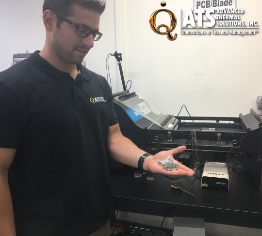
ATS engineer Peter Konstatilakis holds the heat sinks that he designed for cooling QSFP optical transceivers. (Advanced Thermal Solutions, Inc.)
From that project came the idea of examining the thermal challenges presented by SFP and QSFP (quad SFP) and designing a heat sink solution that future customers could use to solve potential issues that stem from the increased power requirements of the compact transceivers that are frequently used in the transmission of data.
After conducting an analytical analysis, running computer simulations, and testing the heat sinks in the state-of-the-art ATS labs, Peter demonstrated a new heat sink design and optimized layout sequence that showed 30 percent improvement on QSFP heat sinks currently on the market.
In addition, he showed that having heat sinks with fewer fins upstream and heat sinks with more fins downstream provided a near isothermal relationship between the first and last QSFP, an important consideration for QSFP arrangements.
Peter recently sat down with ATS Vice-President of Marketing and eCommerce Rebecca O’Day and Marketing Communications Specialist Josh Perry to discuss the project, his research, and the successful design of the new QSFP cooling solution.
JP: What prompted the work on QSFP heat sinks? Why did we start looking into this technology? PK: Optics are pretty big now with all the higher information rates, 400 gigabyte cards, which is 400 gigabytes of throughput and that’s a lot. They need these multiple high-powered SFP or QSFP to do that. So, higher power demands call for ATS expertise in thermal management.
RO: Optics are really expanding. It’s not just routers and things like that, but they’re also used in storage, array networks, video…so this kind of thing could really be able to expand. PK: Anywhere that you are transferring data, which is basically everywhere – the Cloud, big servers, the internet itself. They’re being used a ton.
JP: Was the impetus for designing QSFP heat sinks something that was prompted by a customer or did we think about the technology and recognize that it needed to be cooled? PK: We had worked on SFP cooling for a customer first, so that helped us understand the area a bit more. Also, from what we were hearing from customers, QSFP that were being designed had higher throughput, which means higher power. And it is also good to have products that we can market, even if it isn’t for every customer, and show that we can handle the optical transceiver arena.
JP: What was the first step in designing the heat sinks? Did you know a lot about QSFP or did you have to do a lot of research? PK: There is definitely a lot to think about. You can’t use a TIM (thermal interface material) because the QSFP isn’t fixed in the cage; it can be hot swapped. After a few insertions and removals, it will gunk up the TIM.
JP: Was that something you knew before? PK: It was something I knew before, but there is also a specification document for this technology written by the SFF (Small Form Factor) Committee, which is a standard controlled document that engineers design to for this form factor and it stated in there not to use a TIM. When we looked at it with the customer, it made sense and when we asked the customer they agreed.
RO: If there is no TIM, how does the interface work? Is it a direct interface? Is it flat enough? PK: You have to specify a good enough flatness and surface roughness, within cost means, that will still have a low contact resistance. That was one of the challenges as well as understanding the airflow of typical QSFP arrangements because you have four in a row, so you’re going to have preheated air going into the fourth QSFP.
JP: When designing the heat sinks, what were the issues that you needed to consider? PK: One consideration was getting as much surface area as we can, so that required extending the heat sink off the edge of the cage and we also had fins on the bottom of the heat sink. Usually, you only have fins above the cage but there was some room underneath, about 10 mm depending on what components are around, which provides additional surface area.
We also found that when you extend the surface the spreading resistance becomes an issue as well, so you need to increase the thickness of the base to help spread the heat to the outer extremities of the heat sink. You want the first QSFP and the last QSFP case temperatures’ to be isothermal due to laser performance (an electrical parameter), whereas each individual heat sink should be isothermal to get the most out of all the heat sink surface area (a heat transfer parameter).
‘Cold’ spots insinuate a lack of heat transfer to that location and thus poor use of that surface area. Then it was about the airflow and having the front heat sinks be shorter with fewer fins and the back two to be taller with denser fin arrays.

ATS heat sinks designed specifically for cooling QSFP optical transceivers. (Advanced Thermal Solutions, Inc.)
JP: Was the difference in fin arrays between upstream and downstream heat sinks how you optimized the design to account for the preheated air? PK: What is really important is to keep each QSFP at the same temperature, within reason, because they all work together. So, if one is a higher temperature than another, the laser performance is going to be affected and it will affect the stack. You want to have them as isothermal as you can; the case temperature from the first QSFP to the last.
We figured when we were going through the design, you could have a shorter heat sink up front with fewer fins to help the airflow pass to the downstream QSFP. The upstream QSFP wouldn’t need as much cooling because they’re getting the fresher air and faster airflow. So, if you relax the front heat sinks and make the ones in the back more aggressive, then you’re going to get better cooling downstream.
What happens is the front heat sinks aren’t as effective. This is fine as long as the upstream QSFP case temperatures are lower than the downstream QSFP. The overall effect is that the upstream QSFP temperatures will be closer to the temperature of the downstream QSFP, keeping the stack as isothermal as possible.
This is where the limit lies. Minimizing the upstream QSFP heat sinks, which in turn minimizes the amount of preheat to the downstream QSFP and allows as much airflow to enter downstream QSFP. At the same time ensuring the upstream QSFP temperatures are equal to or just lower than the downstream QSFP. This keeps the downstream QSFP temperatures at a minimum, while also keeping the transceiver stack close to isothermal.
JP: Were there any unexpected challenges that you had to account for? PK: There was a challenge in testing and making sure that the thermocouples (which you can see in the picture below) contact the heat sink surface correctly and all of them at the same point. I had to glue it, so it may touch the case of the heat sink or it may not, depending on how the glue set, so I had to put a little thermal grease inside the pocket just to have the thermocouple make good contact with the heater block itself.
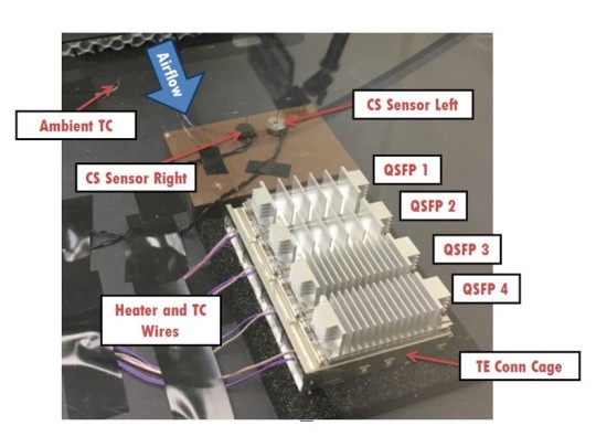
The test setup to measure cooling performance of individual heat sinks on a QSFP connector cage when airflow is from one side only. (Advanced Thermal Solutions, Inc.)
The metal piece (heater block) mimics the QSFP and we put a cartridge heater in the middle to heat it up and then we put a groove where the thermocouple is attached as I just explained.
Other than that…it was really just the flatness. It was hard to test and get reliable data between several heat sinks because there is going to be some flatness variation between them. Sometimes there isn’t enough to show a variation, but if I’m seeing different data with a different heat sink on the same heater block then the flatness and surface roughness is affecting it.
RO: On the flatness issue, in theory someone could spend a lot of money and make sure that it was completely flat but there’s a certain point where it has to be flat enough. PK: Obviously there are diminishing returns after a certain point, so you have to find that line. There are no calculations that explain flatness and surface roughness, so at the end of the day it comes down to testing.
RO: I find it interesting that the testing was a challenge because it appears to us on the outside that this is a standard approach but then you get into it and have to ask how are we going to measure the temperature accurately: PK: There is always something that comes up which you didn’t think about until you start doing the testing and you have to make a change and modify it to make it work. That is where experience comes in handy. The more testing you do, the more you’ve seen and you can take care of the problem before it arises.
RO: It’s a good example of what we can do at ATS. We don’t have to test with a full, expensive board or the full optical arrangement, instead we can come up with inexpensive (low startup cost) ways to test that will provide quick, accurate data to help the customer get to market.
JP: So, we tested three different arrangements for the heat sinks? PK: Yeah. There were two different designs with changes in the density of the fins. Based on the CFD (computational fluid dynamics) and in the lab, the best outcome was having the less dense fins in front for the first two heat sinks and having the denser fin arrays downstream. As we expected, more airflow was able to make it to the back heat sinks and were able to cool them more effectively.
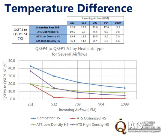
This graph shows the difference in temperature between the ATS heat sinks at various air flows. (Advanced Thermal Solutions, Inc.)
We were seeing less than a degree difference, especially at higher airflows, between the first heat sink and the last and that was pretty impressive. That configuration also provided the lowest temperature for the final two QSFP. Those are going to be the limiting factors; they’re going to be the highest temperature components no matter what since they’re receiving preheated air. That’s why it’s important to minimize the preheated air and maximize the airflow downstream by designing shorter, low fin-density heat sinks upstream.
If you put a dense heat sink up front, you’re going to restrict airflow downstream and you’re going to pull more heat out of the component because it is a better heat sink. With this you’re going to dump more heat into the air and send it to the downstream QSFP. So, it is worth keeping some heat in the upstream components, which has a double effect of keeping all of the QSFP temperatures as isothermal as possible. As long as the upstream components aren’t going over the case temperature of the last component, then you’re fine.
RO: It’s almost counter-intuitive. The general thermal design says to pull as much heat away from the component as quickly as possible and dissipate it, but you’re saying it was better to leave some of the heat in place. PK: For the upstream QSFP, absolutely. There is margin because it is receiving so much fresh air.
That is really because we’re working in a system environment where choices upstream affect the airflow downstream. If it wasn’t a system and you’re looking at a single component, then sure you want to get rid of all the heat. And again, leaving heat in also allows the QSFP components to be as isothermal as possible.
JP: It sounds like it worked the way that you expected going in? PK: Yeah it did. I’m not going to sit here and pretend it always happens that way but what we thought would happen did happen and we were able to design it analytically before we went into CFD and testing.
JP: Were there certain calculations that you use when working with a system? PK: We can look at the fan curve. Each heat sink has its own pressure drop and the way you use a fan curve is to analyze the four heat sinks, add the pressure drops together, and then examine the fan curve (the amount of airflow varies with the pressure that the fan sees) with the higher the pressure, the less airflow. So, we’re able to estimate the amount of airflow across the system based on the total pressure drop.
We also use Q=mCpΔT and that way we can determine, based on the amount of power coming from the component, what is the air temperature that is leaving the heat sink. It is a little conservative because we’re saying that all of the heat is going into the next heat sink, which isn’t true because a little is escaping to other locations, but being conservative doesn’t make a difference when comparing designs.
Analyzing the airflow into each heat sink and the temperature into each heat sink lets us know what we have to design for; just because you’re putting more surface area doesn’t mean you have a good solution.
RO: This is a good example of how thermal management is more than just removing the heat, but also analyzing how the heat travels and thinking about it as a system. It’s much more complicated.
JP: How important is for ATS to be able to see potential thermal challenges in new technology, like this, and work through the problem even if it isn’t for a specific design or customer? PK: It always helps to have more experience. It’s knowledge for the future. We’ve already seen it, we’ve already dealt with it, and we can save time and cost for the customer.
Whenever we run into this issue, we can say we tested that in the lab and explain the solution that we found. We don’t need to do more analysis, but provide the customer with a solution.
For more information about Advanced Thermal Solutions, Inc. (ATS) thermal management consulting and design services, visit https://www.qats.com/consulting or contact ATS at 781.769.2800 or [email protected].
0 notes
Text
IOT temperature logger with GSM transmission and 1wire sensor
Learn how to build your own IoT temperature logger with data uploaded to the cloud. This project uses itbrainpower.net dual SIM full-size GSM shield [a-gsmII] for data transmission (or itbrainpower.net dual SIM full-size GSM GNSS shield [b-gsmgnss]) and Dallas/Maxim 18B20 1wire temperature sensor.
Required time:
30-45 minutes – hardware side
30-60 minutes for software and cloud setup.
Difficulty: intermediate.
IoT hardware – Bill of Materials
Arduino UNO,
a-gsmII v2.105 – Arduino GSM Shield [dual SIM, integrated antenna + uFL, quad-band GSM/GPRS/DTMF/SMS], or
b-gsmgnss v2.105 – Arduino GSM GPS Shield [dual SIM, integrated antenna + uFL, quad-band GSM/GPRS/DTMF/SMS, Bluetooth 3.0, GNSS (GPS+GLONASS)],
A 1WIRE temperature sensor – I use DALLAS/MAXIM 18B20
8.2kb resistor
2G SIM card [with data plan enabled]
some connecting wires
7.5-16V [12V recommended] 1A power source having UNO compatible power jack
Components being assembled
About GSM shields used in this project
We’re using the new a-gsmII v2.105 (Arduino full size GSM shield), together with b-gsmgnss v2.105 (Arduino full size GSM + GNSS (GPS + GLONASS) shield). They’re both Arduino, Teensy, BeagleBone & Raspberry Pi compatible shields. They belong to the next generation of the successfully a-gsm v2.064 and offers to best market performances in their product class, and are offered at a reasonable price.
In this how-to a-gsmII v2.105 shield is used for representation. The very same hardware settings are applied for b-gsmgnss shield [jumpers and connectors are placed in the same position].
The GSM shields documentation can be found here:
a-gsmII documentation
b-gsmgnss documentation
Hardware – Step 1 – 18B20 sensor connection details and references
Solder the 8.2kb resistor between “18B20 Vdd” (pin3) and “18B20 DQ/DATA” (pin2).
DALLAS/MAXIM 18B20 reference here.
18B20 sensor wiring details
Hardware – Step 2 – How to assemble the components together
Below, you can see all the IoT components bound together.
Arduino + GSM temperature IOT sensor wired
Here are the wiring steps to follow:
Solder the Arduino headers to a-gsmII shield
Plug-in the a-gsmII shield into Arduino UNO
Set the a-gsmII “Voltage selector” jumper in “Vin” position
Insert the SIM card in primary SIM socket [a-gsmII/b-gsmgnss – the SIM socket being in the proximity of the PCB]. The SIM must have disabled the PIN-checking procedure (See here for removing PIN check procedure).
Solder the 8k2 resistor to bw. 18B20 Vdd (pin3)and 18B20 DQ/DATA (pin2).
Solder the wires to the 18B20 terminals.
Wire 18B20 Vdd (pin3) to Arduino 5V,
Wire 18B20 DQ/DATA (pin2) to Arduino D8
Wire 18B20 GND (pin1) to Arduino GND.
Connect Arduino UNO USB to your PC
The IOT temperature sensor will be powered via Arduino UNO power barrel connector.
HInt: Multiple 1WIRE temperature sensors are required by your application? Just connect the temperature sensors in parallel mode (single pull up resistor is required, check for proper value), hack the software (use 1,2.. sensorIndex in “sensors.getTempCByIndex(sensorIndex)” and multiple upload sessions). Also, define multiple token sensors in Cloud interface.
Software – Part 1 – Download packages and set IOT variables
Download
either the itbpGSMclass library (beta) “a-gsmII series software IoT REST support for Arduino” from a-gsmII download section
or “b-gsmgnss series software IoT REST support for ARDUINO” from the b-gsmgnss download section. In order to download “itbpGSMclass”, some information is required: the modem’s IMEI (marked to the modem, or can be read using AT+CGSN at command) and your email address.
Expand the archive and install the class and restart the Arduino environment. More details about manual library installing, read Arduino library manual installation.
Create a folder named agsmII_temperature_Robofun_cloud_logger.
Download the main code from agsmII_temperature_Robofun_cloud_logger.ino – main code and save it with that name in the folder created in the previous step.
You’ll need to set up some variables in agsmII_temperature_Robofun_cloud_logger.ino: – tempToken (line 19) – replace with the sensor token generated on Robofun Cloud (see below) – samplingPeriod (line 29)
You’ll need to set up some variables in itbpGSMclass library:
Set SERVER_ADDRESS and SERVER_PORT in itbpGPRSIPdefinition.h for Robofun Cloud #define SERVER_ADDRESS “iot.robofun.ro” #define SERVER_PORT “80”
Set APN, USERNAME and PASSWORD for your SIM card in itbpGPRSIPdefinition.h
Choose itbrainpower modem used in itbpGSMdefinition.h, in this example: #define __itbpModem__ agsmII
Software – Part 2 – Cloud setup tasks. Define new sensor. Copy TOKEN data
I’ve chosen Robofun Cloud because it is a very easy-to-use cloud service and the usage it’s free of charge. Next, I will guide your steps to set up the cloud service account and sensor.
Create a new account at https://iot.robofun.ro
Account creation screen
Create a new sensor
Add sensor
Chose a name for your sensor
Add a name to your sensor
Scroll down the page to the section named Token
Sensor Token Data
Copy your sensor Token ID. Use this value for the tempToken variable at line 19 in agsmII_temperature_Robofun_cloud_logger.ino.
Compile the Arduino project and upload it to your Arduino UNO. Now, your temperature sensor is ready to upload temperature data samples to the Robofun Cloud service.
If you need to debug, use Arduino serial monitor (speed was chosen to 115200bps).
How to visualize temperature log records
Visualize temperature log records links
Cloud stored temperature data can be visualized in your cloud sensor page, or in public page.If you want to enable the public page, scroll up the page until “Share sensor” chapter, and follow the link.
Congratulations! Your 1 wire temperature data logger is ready!
TUTORIAL PROVIDED WITHOUT ANY WARRANTY – USE IT AT YOUR OWN RISK. Originally written by Dragos Iosub & itbrainpower.net team and published on itbrainpower.net


Related Stories
LiDAR : Light & laser based distance sensors
DIY Perimeter Wire Generator and Sensor
How to find the right battery? Crashbotics S01E01
from RobotShop Blog Feed https://ift.tt/2DWSb6e via IFTTT
0 notes
Text
4G antenna price official flagship store of 4G antenna
dingzi.com provides you with the latest information about the price of 4G antenna. For more information about the official flagship communication antenna manufacturer store of 4G antenna, please pay attention to us.
TP-LINK home Mini 300m wireless router 2 antenna 100m cable port 2.4G high speed WiFi through wall AP mobile telecom Unicom Network fiber broadband tl-wr842n commodity price 85, from Shanghai, the seller is the speedstar office store.
2450at45a100 2.4G Bluetooth WiFi signal chip ceramic antenna gain 3dBi commodity price 2, from Shenzhen, Guangdong Province, the seller is Shengji digital flagship store.
2.4g15db omnidirectional antenna high gain wireless routing wireless network card monitoring wifi antenna SMA interface commodity price 20, from Shenzhen, Guangdong Province, the seller is Jiayuan digital flagship store.
Totolink original 8dB wireless router network card 2.4G copper core 8dbi omnidirectional SMA gain antenna a008 commodity price 25, from Shenzhen, Guangdong Province, the seller is xinjialong digital exclusive store.
2.4G 4dB built-in PCB antenna WiFi module antenna high gain omnidirectional antenna IPEX commodity price 2, from Shenzhen, Guangdong Province, the seller is tekabao flagship store.
4g-lte / 3G / GSM / GPRS wall mounted flat panel antenna WiFi / 2.4G directional indoor and outdoor CPE high gain commodity price 50, from Guangzhou, Guangdong, the seller is dLENP Zhonghe Jiaxin monopoly.
Risym industrial nRF24L01 + PA + LNA data transmission wireless module remote / dual antenna / 2.4G commodity price 40, from Shenzhen, Guangdong Province, the seller is risym flagship store.
South Korea Aidi Cowon CF2 in ear Bluetooth headset 5.0 ceramic antenna dual host 4G non feeling wearer hifi waterproof and dustproof IPx4 commodity price 699, from Beijing, the seller is Tianyu Lianda digital exclusive store.
An9520-245 2.4G omnidirectional antenna Bluetooth antenna ceramic patch WiFi built-in commodity price 2, from Shenzhen, Guangdong Province, the seller is shengxinglong digital exclusive store.
2.4G omnidirectional antenna an9520-245 Bluetooth antenna 9mm built-in ceramic chip WiFi commodity price 1, from Shenzhen, Guangdong Province, the seller is Shengji digital flagship store.
2.4G 4dB module antenna IPX IPEX WiFi module antenna omnidirectional high gain built-in antenna commodity price 2, from Shenzhen, Guangdong Province, the seller is tegate digital exclusive store.
NRF24LE1 PA + LNA module / 24L01 / long distance nRF24LE1 module / 2.4G antenna with commodity price of 45, from Shenzhen, Guangdong Province, the seller is jinlixiangda digital exclusive store.
17dbi 2.4G 120 degree dual polarization wireless WiFi sector high gain directional antenna n head commodity price 450, from GuangdongShenzhen, the seller is lafalink flagship store.
2.4g10dbi directional radar antenna SMA interface wireless network card wireless routing wireless WiFi gain antenna commodity price 14, from Shenzhen, Guangdong Province, the seller is Jiayuan digital flagship store.
Huaxin 2.4G copper tube antenna 3dB omnidirectional antenna module small antenna wifi antenna IPEX interface commodity price 2, from Shenzhen, Guangdong Province, the seller is jiashitong digital exclusive store.
July 23, 2020: it is a genuine product, and the price is higher in the physical store, or it is more affordable to do online shopping.
July 23, 2020 Good
2020-07-23:4g antenna price, cosmetic effect is not very good, but the price is where, want the ideal effect please do not shoot
2020-07-23:4g antenna price, used countless bottles, so far found the best use of make-up, clean, no stimulation, unlimited buy back
2020-07-23: customer service Xiao Qiao, the efficiency is excellent? Satisfied! After using it, we should review
2020-07-23: 11 pairs of bought, one of the mask has been leaked, and the cleansing cream does not delay
.
0 notes