#Electronics Resistor Color Code
Explore tagged Tumblr posts
Visit Tumblr Blog
Explore Tumblr blogs with no restrictions, modern design and the best experience.
Last Seen Tumblr Blogs


Fun Fact
Tumblr was named as a finalist in Lead411’s New York City Hot 125 in Aug 2010.
Text
I was feeling all self-congratulatory for deciding to wire up the jacks on the Breakout with rainbow-colored ribbon cable; I thought it'd make the whole thing more tidy and easier to understand.

Turns out, not so much.
There are three problems that contribute to this spaghetti — in which, mind, only the first bank of six jacks is fully wired. First, the ribbon cables really aren't long enough for each one to have its wires be split out to the jacks — and there aren't really enough conductors in each wire to feel secure about bending them around a lot — so I'm needing to splice on these silicone-coated stranded wires to each one, and then connect those to the jacks. Which leads to problem 2: I don't have discrete wires in all the colors of the ribbon cable, so I'm having to double up and have, e.g., red connect to itself, to orange, and to brown.
The third problem is a little more esoteric. See, electronics stuff usually all follows the same numerical color code. If you've ever had to figure out the value of a resistor by looking at its colored rings, it's the same order of digits as the rainbow ribbon cable, a mostly spectrum order: black is 0, brown is 1, then red, orange, yellow, green, blue, violet, gray, white, and then the cycle repeats. So because the ports have eight pins (numbered 1-6 and then two grounds), I made up the cables to match that count, brown through gray.

(Image by Knarfili on Wikimedia.)
And that's where I went wrong. See, the headers on the board are laid out in a nice easy counting order, and IDC connectors on ribbon cable are in a nice easy counting order, but they're not the same order.
So my color-to-number order is all messed up.

So the upshot is that I'm having to remember that the orange wire is actually 2, not 3, and the red wire is 5, not 2 — but then I have to connect both of those to different red wires anyway! Aaaugh.
The upshot is that it's just a matter of going through the wires one at a time and double checking that the right pins are connected to the right jacks, and all my attempts at making things easier haven't. Ah, well.
2 notes
·
View notes
Text
Confused by those colorful bands on resistors? 🤯 Don’t worry — we’ve got you covered! Check out our beginner-friendly guide on Resistor Color Coding and learn how to decode resistor values with ease. 🎨⚡
Whether you're starting your electronics journey or brushing up your skills, this article is packed with clear examples, practical tips, and a handy color chart!
0 notes
Text
I think both are symptomatic of an itch to take symbolic gestures way too seriously.
It’s likely the same itch behind the idea that burning the US Flag is so offensive that people should be put behind bars for it, or lose their citizenship for burning a fucking strip of fabric.
Sometimes, I think the reductive itch can be more logical and pragmatic.
The Philadelphia flag with the black and brown stripes reminds me of the chart for electronic resistor value color code. I think it somewhat works. But without discounting the major contributions that queer people of color have done for LGBTQ rights… sexuality and gender identity aren’t race. Not all LGBTQ people are of color. Being LGBTQ doesn’t make your experience “like someone of color”. So I think the Philly flag should specifically be dedicated to LGBTQ people of color, not LGBTQ in general.
The original eight striped flag looked aesthetically pleasing and emphasized sexuality with the pink stripe, but are we really going to act like something is wrong with the six striped version?
If I personally don’t like blue pink and white, do I get to tell everyone else to take down their trans flags for a newer version that looks more like the Thai flag or a Tommy Hilfiger sweater? Perhaps not.
I’m a descriptivist and an advocate for flexible norms of communication. Someone who says “transgenders” isn’t automatically a non-ally. I sometimes think emphasis on the formalities of it all makes the lack of symbolic gestures… the lack of BLM in your bio… look like a lack of actual support… a lack of support for black lives.


these feel similar to me
5K notes
·
View notes
Text
ASVAB Online Study Guideline To Score High
The Armed Services Vocational Aptitude Battery is a crucial test for anyone looking to enlist in the U.S. Navy. Your ASVAB scores determine your eligibility for enlistment and influence the types of jobs available to you within the Navy.

Officer Aptitude Rating (OAR) test is an essential part of the U.S. Navy's selection process, and the Physical Electronics section plays a significant role in the test.
Inductor in a Circuit
What is the purpose of an inductor in a circuit?
A) To resist changes in voltage
B) To resist changes in current
C) To store energy as an electric field
D) To store energy as a magnetic field
(practice question answer me!!)
What is the value of a resistor with the color code red, blue, green, and gold?
A) 2700 Ω
B) 27000 Ω
C) 27 Ω
D) 270000 Ω
(practice question answer me!!)
Join Us At ASVAB Online Classes & get course materials 👈 For Preparation.
#air force#carrier aviation#military#navy#royal navy#us army#us marines#us navy#marine biology#helicopter#asvab online courses#asvab online classes#asvab test prep#asvab study tips#asvab prep
1 note
·
View note
Text
Arduino what now??
This project is SUPPOSED to open doors and insights into the world of makerspaces and coding through the Arduino circuit board. Right now it's making me want to pull my hair out and drink way more Diet Dr. Pepper than I need.
This is the code from example circuit #3. I learned that if i anything is out of place- IT WILL NOT WORK!! This is the rainbow circuit...
/*
Example sketch 03
RGB LED
Make an RGB LED display a rainbow of colors!
Hardware connections:
An RGB LED is actually three LEDs (red, green, and blue) in
one package. When you run them at different brightnesses,
the red, green and blue mix to form new colors.
Starting at the flattened edge of the flange on the LED,
the pins are ordered RED, COMMON, GREEN, BLUE.
Connect RED to a 330 Ohm resistor. Connect the other end
of the resistor to Arduino digital pin 9.
Connect COMMON pin to GND.
Connect GREEN to a 330 Ohm resistor. Connect the other end
of the resistor to Arduino digital pin 10.
Connect BLUE to a 330 Ohm resistor. Connect the other end
of the resistor to Arduino digital pin 11.
This sketch was written by SparkFun Electronics,
with lots of help from the Arduino community.
Visit http://www.arduino.cc to learn about the Arduino.
Version 2.0 6/2012 MDG
*/
// First we'll define the pins by name to make the sketch
// easier to follow.
// Here's a new trick: putting the word "const" in front of a
// variable indicates that this is a "constant" value that will
// never change. (You don't have to do this, but if you do, the
// Arduino will give you a friendly warning if you accidentally
// try to change the value, so it's considered good form.)
const int RED_PIN = 9;
const int GREEN_PIN = 10;
const int BLUE_PIN = 11;
// This variable controls how fast we loop through the colors.
// (Try changing this to make the fading faster or slower.)
int DISPLAY_TIME = 100; // In milliseconds
void setup()
{
// Here we'll configure the Arduino pins we're using to
// drive the LED to be outputs:
pinMode(RED_PIN, OUTPUT);
pinMode(GREEN_PIN, OUTPUT);
pinMode(BLUE_PIN, OUTPUT);
}
void loop()
{
// In this sketch, we'll start writing our own functions.
// This makes the sketch easier to follow by dividing up
// the sketch into sections, and not having everything in
// setup() or loop().
// We'll show you two ways to run the RGB LED.
// The first way is to turn the individual LEDs (red, blue,
// and green) on and off in various combinations. This gives you
// a total of eight colors (if you count "black" as a color).
// We've written a function called mainColors() that steps
// through all eight of these colors. We're only "calling" the
// function here (telling it to run). The actual function code
// is further down in the sketch.
mainColors();
// The above function turns the individual LEDs full-on and
// full-off. If you want to generate more than eight colors,
// you can do so by varying the brightness of the individual
// LEDs between full-on and full-off.
// The analogWrite() function lets us do this. This function
// lets you dim a LED from full-off to full-on over 255 steps.
// We've written a function called showSpectrum() that smoothly
// steps through all the colors. Again we're just calling it
// here; the actual code is further down in this sketch.
showSpectrum();
}
// Here's the mainColors() function we've written.
// This function displays the eight "main" colors that the RGB LED
// can produce. If you'd like to use one of these colors in your
// own sketch, you cancopy and paste that section into your code.
void mainColors()
{
// Off (all LEDs off):
digitalWrite(RED_PIN, LOW);
digitalWrite(GREEN_PIN, LOW);
digitalWrite(BLUE_PIN, LOW);
delay(1000);
// Red (turn just the red LED on):
digitalWrite(RED_PIN, HIGH);
digitalWrite(GREEN_PIN, LOW);
digitalWrite(BLUE_PIN, LOW);
delay(1000);
// Green (turn just the green LED on):
digitalWrite(RED_PIN, LOW);
digitalWrite(GREEN_PIN, HIGH);
digitalWrite(BLUE_PIN, LOW);
delay(1000);
// Blue (turn just the blue LED on):
digitalWrite(RED_PIN, LOW);
digitalWrite(GREEN_PIN, LOW);
digitalWrite(BLUE_PIN, HIGH);
delay(1000);
// Yellow (turn red and green on):
digitalWrite(RED_PIN, HIGH);
digitalWrite(GREEN_PIN, HIGH);
digitalWrite(BLUE_PIN, LOW);
delay(1000);
// Cyan (turn green and blue on):
digitalWrite(RED_PIN, LOW);
digitalWrite(GREEN_PIN, HIGH);
digitalWrite(BLUE_PIN, HIGH);
delay(1000);
// Purple (turn red and blue on):
digitalWrite(RED_PIN, HIGH);
digitalWrite(GREEN_PIN, LOW);
digitalWrite(BLUE_PIN, HIGH);
delay(1000);
// White (turn all the LEDs on):
digitalWrite(RED_PIN, HIGH);
digitalWrite(GREEN_PIN, HIGH);
digitalWrite(BLUE_PIN, HIGH);
delay(1000);
}
// Below are two more functions we've written,
// showSpectrum() and showRGB().
// showRGB() displays a single color on the RGB LED.
// You call showRGB() with the number of a color you want
// to display.
// showSpectrum() steps through all the colors of the RGB LED,
// displaying a rainbow. showSpectrum() actually calls showRGB()
// over and over to do this.
// We'll often break tasks down into individual functions like
// this, which makes your sketches easier to follow, and once
// you have a handy function, you can reuse it in your other
// programs.
// showSpectrum()
// This function steps through all the colors of the RGB LED.
// It does this by stepping a variable from 0 to 768 (the total
// number of colors), and repeatedly calling showRGB() to display
// the individual colors.
// In this function, we're using a "for() loop" to step a variable
// from one value to another, and perform a set of instructions
// for each step. For() loops are a very handy way to get numbers
// to count up or down.
// Every for() loop has three statements separated by semicolons:
// 1. Something to do before starting
// 2. A test to perform; as long as it's true,
// it will keep looping
// 3. Something to do after each loop (usually
// increase a variable)
// For the for() loop below, these are the three statements:
// 1. x = 0; Before starting, make x = 0.
// 2. x < 768; While x is less than 768, run the
// following code.
// 3. x++ Putting "++" after a variable means
// "add one to it". (You can also use "x = x + 1")
// Every time you go through the loop, the statements following
// the loop (those within the brackets) will run.
// And when the test in statement 2 is finally false, the sketch
// will continue.
void showSpectrum()
{
int x; // define an integer variable called "x"
// Now we'll use a for() loop to make x count from 0 to 767
// (Note that there's no semicolon after this line!
// That's because the for() loop will repeat the next
// "statement", which in this case is everything within
// the following brackets {} )
for (x = 0; x < 768; x++)
// Each time we loop (with a new value of x), do the following:
{
showRGB(x); // Call RGBspectrum() with our new x
delay(10); // Delay for 10 ms (1/100th of a second)
}
}
// showRGB()
// This function translates a number between 0 and 767 into a
// specific color on the RGB LED. If you have this number count
// through the whole range (0 to 767), the LED will smoothly
// change color through the entire spectrum.
// The "base" numbers are:
// 0 = pure red
// 255 = pure green
// 511 = pure blue
// 767 = pure red (again)
// Numbers between the above colors will create blends. For
// example, 640 is midway between 512 (pure blue) and 767
// (pure red). It will give you a 50/50 mix of blue and red,
// resulting in purple.
// If you count up from 0 to 767 and pass that number to this
// function, the LED will smoothly fade between all the colors.
// (Because it starts and ends on pure red, you can start over
// at 0 without any break in the spectrum).
void showRGB(int color)
{
int redIntensity;
int greenIntensity;
int blueIntensity;
// Here we'll use an "if / else" statement to determine which
// of the three (R,G,B) zones x falls into. Each of these zones
// spans 255 because analogWrite() wants a number from 0 to 255.
// In each of these zones, we'll calculate the brightness
// for each of the red, green, and blue LEDs within the RGB LED.
if (color <= 255) // zone 1
{
redIntensity = 255 - color; // red goes from on to off
greenIntensity = color; // green goes from off to on
blueIntensity = 0; // blue is always off
}
else if (color <= 511) // zone 2
{
redIntensity = 0; // red is always off
greenIntensity = 255 - (color - 256); // green on to off
blueIntensity = (color - 256); // blue off to on
}
else // color >= 512 // zone 3
{
redIntensity = (color - 512); // red off to on
greenIntensity = 0; // green is always off
blueIntensity = 255 - (color - 512); // blue on to off
}
// Now that the brightness values have been set, command the LED
// to those values
analogWrite(RED_PIN, redIntensity);
analogWrite(BLUE_PIN, blueIntensity);
analogWrite(GREEN_PIN, greenIntensity);
}
3. The pictures that follow are the Arduino Board and the first successful code...A BLINKING LIGHT!!


4. The husband and I decided we would play around with creating the "Love Meter". It has not worked yet but here is our first attempt!

5. This video is of the first code the "blinking light". I was pretty excited that it worked the first time!
6. My post only allows for one video so text it is! When I first started this project, I opened the box and saw all the pieces and became overwhelmed. You'd think as someone who literally works as an Instructional Technologist I would have been a little more excited. I got to work on reading ALL about the materials and their functions. The starter guide book has been my best friend and YouTube. the husband may have helped when the tears began to start. 😂
7. Really I was just learning about the pieces and the mechanics of each piece and the coding examples. I read the user manual, looked at examples, and watched YouTube videos to help me through the process. Through lots of frustration, trial and error, and time, I was able to successfully download the software, get the light to blink and create the rainbow light circuit. Well, put the pieces and wires where they go and run the code provided. Learning how to actually "code" is going to be my greatest challenge.
0 notes
Text
Harley Davidson Wiring Diagrams & Electrical: A Comprehensive Guide
Harley Davidson motorcycles are iconic, representing a blend of power, heritage, and innovation. But beneath their rugged exterior lies a complex network of wiring and electrical systems that are crucial to their operation.
Harley Davidson wiring diagrams and electrical systems can be a game-changer for any motorcycle enthusiast, whether you’re performing routine maintenance, troubleshooting, or embarking on a custom build.

1. Introduction to Harley Davidson Wiring Systems
Harley Davidson motorcycles have evolved significantly over the years, and so have their electrical systems. Modern Harleys are equipped with sophisticated electronics that control everything from lighting to ignition, while older models rely on simpler, more mechanical systems.
Regardless of the model, understanding the wiring is key to keeping your Harley running smoothly.
2. Why Wiring Diagrams are Essential
A wiring diagram is essentially a road map for the electrical system of your motorcycle. It shows the connections between various components and helps you understand how electricity flows through the system. For Harley Davidson motorcycles, wiring diagrams can assist in:
Troubleshooting Electrical Issues: Identifying and resolving electrical problems, such as a non-starting engine or malfunctioning lights.
Customization: Installing aftermarket parts like custom lighting or audio systems.
Maintenance: Performing routine checks and ensuring all electrical connections are secure and functioning properly.
3. Key Components of Harley Davidson Electrical Systems
Understanding the key components of Harley Davidson’s electrical system is essential for interpreting wiring diagrams:
Battery: The heart of the electrical system, providing the necessary power to start the engine and run electrical components.
Ignition Switch: Controls the power flow from the battery to the rest of the electrical system.
Fuse Box: Protects the electrical circuits from overloads by breaking the circuit if too much current flows through.
Relays: Used to control high-power circuits with low-power signals, such as turning on the headlights or horn.
Connectors and Wires: The veins of the electrical system, connecting components and allowing electricity to flow.
ECU (Electronic Control Unit): In modern Harleys, the ECU controls various functions like fuel injection and ignition timing.
4. How to Read a Harley Davidson Wiring Diagram
Wiring diagrams can seem daunting at first, but once you understand the symbols and layout, they become invaluable tools. Here’s a quick guide:
Symbols: Each component is represented by a symbol, such as a circle for a light bulb or a zigzag line for a resistor.
Lines: These represent the wires connecting the components. Solid lines usually indicate a direct connection, while dashed lines may represent optional or alternative connections.
Color Codes: Wiring diagrams often use color codes to differentiate wires. For instance, a black wire might represent a ground connection, while a red wire indicates power.
5. Common Wiring Issues in Harley Davidson Motorcycles
While Harley Davidson motorcycles are built to last, electrical issues can arise due to wear and tear, improper installations, or accidents. Common issues include:
Short Circuits: Caused by damaged wires or connections, leading to blown fuses or non-functional components.
Corroded Connections: Moisture can lead to corrosion at connection points, resulting in poor electrical conductivity.
Battery Drain: A faulty relay or short circuit can cause the battery to drain even when the motorcycle is off.
Faulty Relays: Relays can wear out over time, leading to intermittent or complete loss of function in systems like lighting or starting.
6. Troubleshooting Tips
Use a Multimeter: A multimeter can help you measure voltage, continuity, and resistance, making it easier to pinpoint electrical issues.
Check Fuses First: Always check the fuse box if something stops working. It’s often the simplest and quickest fix.
Inspect Wires and Connections: Look for any signs of wear, corrosion, or loose connections.
7. Upgrading Your Harley’s Electrical System
If you’re looking to upgrade your Harley Davidson, understanding the wiring diagram is crucial. Common upgrades include:
LED Lighting: LED lights are more energy-efficient and brighter than traditional bulbs, but they may require new relays or resistors.
Audio Systems: Adding a sound system requires tapping into the electrical system without overloading it.
Custom Gauges: Installing aftermarket gauges or displays can enhance the look and functionality of your bike.
Conclusion
Harley Davidson wiring diagrams and electrical systems is essential for any motorcycle enthusiast. Whether you're maintaining your bike, troubleshooting an issue, or planning an upgrade, a solid grasp of the electrical system will help you keep your Harley running smoothly for years to come.
With the right tools and knowledge, you can confidently tackle electrical challenges and enjoy the open road on your Harley Davidson.
#Harley Davidson#Wiring Diagrams & Electrical#Harley Davidson Wiring Diagrams & Electrical#Harley Wiring Diagrams & Electrical#Davidson Wiring Diagrams & Electrical
1 note
·
View note
Text
What Are Some Fun Facts About Electronics?
Do you know the surprising fun facts about electronics that have revolutionized our world?
Let us study some fascinating and unexpected details regarding the electrical gadgets that are all around us.

What are some fun facts about electronics?
1. The First Transistor
At Bell Laboratories, John Bardeen, William Shockley, and Walter Brattain created the first transistor in 1947. This little gadget created the foundation for modern computing and changed electronics.
2. Silicon Valley’s Origins
The region of California famed for its tech companies is referred to as "Silicon Valley." Its significant concentration of businesses producing silicon chips is how it gained its moniker.
3. Tiny Transistors Facts about Electronics
Transistors nowadays are remarkably tiny. Some are thousands of times smaller than human hair, measuring only a few nanometers in width.
4. Moore’s Law
Moore's Law, so named for Intel co-founder Gordon Moore, states that as microchip transistor counts double roughly every two years, computing power will increase and transistor costs will decrease.
5. The Oldest Computer
An ancient analog computer from approximately 100 BC was found on a shipwreck off the coast of Greece. It is known as the Antikythera mechanism. Eclipses and astronomical positions were predicted with its help.
6. Quantum Computers Facts about Electronics
Quantum computers use qubits, which are particles that may simultaneously represent and process 0s and 1s, in place of classical computers, which use bits (0s and 1s). This might be able to address challenging issues far more quickly than current supercomputers.
7. Integrated Circuits
Initially created in 1958 by Jack Kilby at Texas Instruments and Robert Noyce at Fairchild Semiconductor, the integrated circuit (IC) is a device that combines several electronic components onto a single chip. This invention had a significant role in the growth of modern electronics.
8. The World’s Smallest Computer
Some of the tiniest computers available today are only a few millimeters in size because of recent improvements. Environmental sensors and medical implants frequently use these tiny devices.
9. LED Evolution Facts about Electronics
Nick Holonyak Jr. created the first usable LED (Light Emitting Diode) in 1962. It sent off a red glow. LEDs are used in everything from energy-efficient lights to display screens nowadays, and they come in a range of colors.
Read: Fun Facts About the Gorilla Especially the Number 3
10. Electricity’s Speed
The real drift speed of electrons in a conductor is very slow, about the speed of electricity, which is more accurately the speed of the electromagnetic field carrying electrical energy. The electromagnetic wave is what gives the impression that energy moves quickly.
11. Capacitors in Cameras
Capacitors are used in digital cameras, particularly the earlier types, to store energy for the flash. They have the rapid release of a great deal of energy, which produces the brilliant flash of light.
12. The Internet of Things (IoT)
The network of linked gadgets that communicate with one another through the internet is referred to as the Internet of Things. This idea goes beyond cellphones and computers to cover commonplace appliances like lightbulbs, refrigerators, and thermostats.

13. Resistor Color Codes Facts about Electronics
The resistance value of resistors is indicated by color bands. The color coding scheme was created and has been in use for many years to make it easier to identify resistor values. A resistor with red, red, and brown bands, for instance, signifies a resistance of 220 ohms.
14. The Power of Vacuum Tubes
Vacuum tubes were the main component of early computers and radios before transistors. They were significant in the creation of the first electronic gadgets because they could amplify electrical signals.
15. Nobel Prize in Physics
The transistor's creators were granted the 1956 Nobel Prize in Physics in recognition of their groundbreaking creation. This was a turning point in the history of electronics.
16. Memory and Speed Facts about Electronics
Processor and memory speeds in computers have increased quickly. In the case of modern computers typically have memory measured in gigabytes (GB) or even terabytes (TB), whereas early personal computers' memory was measured in kilobytes (KB).
more >>>
1 note
·
View note
Text
I found a Wikipedia page with mnemonics for the color codes on resistors. The ones in the "Offensive/Outdated" section are almost all horrible. But this one is just the best ever:
Batman blows Robin on yon Gotham bridge; Very good Wayne! Get Superman Next!
(Black, brown, red, orange, yellow, green, blue, violet, gray, white; gold, silver, none for the tolerance)
1 note
·
View note
Text
Through Hole Resistors: The Unsung Heroes of Electronics
In the vast and intricate world of electronics, there’s a small yet essential component that often goes unnoticed — the through hole resistor. These unassuming devices play a crucial role in shaping the functionality of countless electronic gadgets we use every day, from your trusty toaster to the sleek smartphone in your pocket.
Let’s take a closer look at the humble through hole resistor and unravel the mystery behind this tiny but mighty component.
What’s in a Name?
The name might sound technical, but fear not; understanding through hole resistors is simpler than it seems. Imagine them as the traffic controllers of the electronic world, regulating the flow of current and preventing chaos in your devices. Unlike their more modern counterpart, the surface-mount resistor, through hole resistors have leads that pass through holes in the circuit board, hence the name.
The Anatomy of a Through Hole Resistor
Picture a small cylindrical device with color bands wrapped around it — that’s your through hole resistor. These color bands are not just for aesthetics; they convey valuable information about the resistor’s resistance value, tolerance, and sometimes even its temperature coefficient. It’s like a secret code that engineers and hobbyists decipher to ensure they’re using the right component for the job.
Resisting the Flow
At its core, a through hole resistor resists the flow of electrical current. It acts as a barrier, controlling the amount of electricity that passes through a circuit. This resistance is measured in ohms, and the color bands on the resistor help you determine this value. It’s like the resistor’s way of saying, “This is how much resistance I bring to the table.”
Tolerance: Embracing Imperfection
No one is perfect, and neither are through hole resistors. Each resistor comes with a tolerance value, indicating how much its actual resistance can deviate from the stated value. Tolerance is a critical aspect when selecting resistors for precision applications. It’s like acknowledging that even the most reliable friend can occasionally be fashionably late.
Applications Galore
Through hole resistors are versatile and find applications in a myriad of electronic devices. Whether it’s in the amplifier of your favorite audio system or the heart of a digital clock, these little wonders quietly do their job without demanding the spotlight. Their reliability and simplicity make them the go-to choice for various electronic circuits.
DIY Delight
For electronics enthusiasts and hobbyists, through hole resistors are a gateway to countless DIY projects. Building your own gadgets or tweaking existing ones becomes a thrilling adventure, with these resistors playing a starring role. Their accessibility and affordability make them an excellent choice for those just dipping their toes into the vast ocean of electronics.
In the symphony of electronic components, through hole resistors are the unsung heroes, quietly shaping the harmony of our technological world. As we marvel at the sleek design of our gadgets and the seamless connectivity they offer, let’s not forget to appreciate the small but mighty through hole resistor — the unassuming guardian of our electronic realms. Next time you flip a switch or press a button, remember that there’s a through hole resistor somewhere in the circuit, dutifully playing its part in keeping the electrons in check.
0 notes
Text
Hmmmm
#mini vent i guess?#tbh its not that bad#but i feel a bit sick in the mouth#basically in a lecture yeah#and we're talking about color codes on resistors (im doing electronic engineering for ref)#and there was an old rhyme to remember it and it's.... disgusting#the lecturer refused to say it on camera but we all looked it up out of morbid curiosity#and yikes... its so bad...#really violent towards women#i don't want to say it because uts so disgusting its kinda making my head spin a lil#im ok just... disturbed#i mean now it's not used at all because as i said its bad#but god... engineering as a woman is... oof...#im ok though ilk probably delete this later just needed to get this off my chest
3 notes
·
View notes
Photo

Resistance Color Coding | Important Post ---------------------------------------------------------------------------------- Like👍 ll comments📝 II Share📢 ➡️Keep Supporting🙏 ---------------------------------------------------------------------------------- . . ---------------------------------------------------------------------------------- Follow (@nationin) for more stuff. ---------------------------------------------------------------------------------- . . _____________________________________________________ #electronics #electronspark #electronicsolvers #electronicsolution #electronicsengineering #resistor #color #coding #voltage #electrical #electricalengineering #electricalengineers #ohms #wires #mechatronics #arduinolove #arduinofun #circuitdesign #semiconductor #engineering #engineers #technology #robot #electronicsproject #sensor #electricals #electronique#technopark #technopeople https://www.instagram.com/p/B-yWuVAD4sr/?igshid=1wstm0onahr3w
#electronics#electronspark#electronicsolvers#electronicsolution#electronicsengineering#resistor#color#coding#voltage#electrical#electricalengineering#electricalengineers#ohms#wires#mechatronics#arduinolove#arduinofun#circuitdesign#semiconductor#engineering#engineers#technology#robot#electronicsproject#sensor#electricals#electronique#technopark#technopeople
0 notes
Text
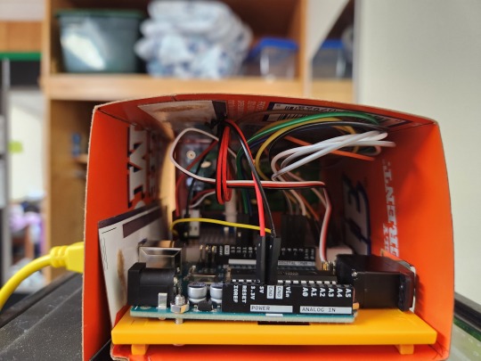
Project 14 - Automatic Fish Feeder
Since the class has completed all the assignments from the Arduino projects book, we're moving onto more advanced projects we came up with on our own for the rest of the semester.
My first project is an Automatic Fish Feeder! This one is designed to release one feeding 12 hours after starting. Perfect for a weekend away to keep your fish happy!
expand the post to see how to make it. This one is really long since I'm sharing how I built everything as well as some of my thought processes.
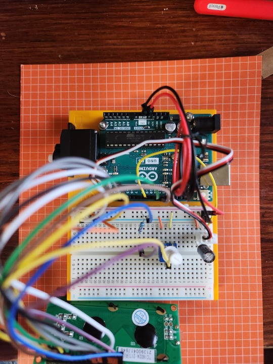
Needed Materials:
Electronic parts:
• LCD
• 220 Ohm resistor
• Servo
• Potentiometer
• Capacitor
• Long Male/Female wire extenders
Building materials:
• Thin cardboard (I used a soda can box)
• Glue stick
• Bobby pin
• Adhesive dots
• Electric tape
• Printed decorations (Optional, just for aesthetics)
How It's Made:
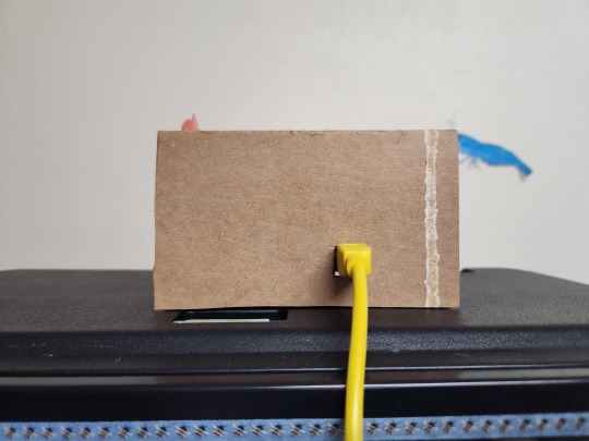
Using thin cardboard as my main building material, I traced the footprint of the Arduino + breadboard base and eyeballed how tall the sides should be. I'll include measurements below so you don't have to guess like I did. I also made sure to leave room for the servo to poke out as well as a spot for the power cable to be plugged in.
I used an adhesive dot to stick the servo to plastic base my Arduino is on.
the front panel is a separate piece of cardboard. I traced the LCD's footprint onto the front and cut it out with a knife. The thin cardboard wasn't strong enough to hold the weight of the screen, so I made a second front panel and glued it to the first. I also left room around the edges when I was cutting out so I would have surface area to glue things together.
The food receptacle is traced from a pencil sharpener I had on hand, so I'll include the measurements in my mockup for your pleasure. It's just a rectangle with an open top and bottom. Just for fun, I glued a little strip of colorful cardboard to the bottom edge of the box.
For the trap door on the bottom of the food bin, I traced the bottom of the rectangle and cut out two. Cut the wavy leg off a bobby pin. Glue the remaining straight leg between the two cut outs, make sure it's off center(as seen in picture X). Use electric tape to secure the rounded part of the bobby pin to the little servo arm. Stretch the tape as you put it on to make sure it's secure.
Finally, I spiced up the outside of the build with some labels and pictures. I have a small thermal sticker printer, but any printed or hand written markings will do. I stuck the fish image to a cardboard scrap and cut it out before gluing it above the LCD. Having it come off the edge of the box adds a lot of visual interest to an otherwise boring build.


Graphic of build plus measurements:

Board:
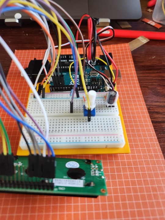
The Code:
Once the Arduino turns on, it starts counting up until the dispense time - start time = 0. Then the servo will rotate it's arm to 180° and dump the food into your fish tank. The LCD screen will display a welcome message before showing the time remaining until the food gets dispensed. For the demonstration, I changed the code to dump the food after 10 seconds and display the time remaining in seconds. You can comment that out and comment in the 12 hour pre programmed time if you want to actually use this build.
Video:
youtube
Schematics:

and a picture of my fish because I love him so much. His name is Horatio

2 notes
·
View notes
Text
3DS capture cards are a thing but they're still very underground. Why?
I love my Nintendo 3DS. I am not a corporate shill. I promise.
Seriously though, my 3DS has some really cool games and its a shame that streaming/recording footage is such a hassle and limited by so many things. I'd prefer to stream off real hardware than an emulator for a variety of reasons including but not limited to the (current) amount of games that Citra can't run without major issues in some capacity. So with that off the table, what are my options?
Well, hardware capture is expensive right now. Not accounting for *gestures vaguely at everything involving the supply chain from 2020 to 2022* most places local to the US and UK make you pay out of pocket for a new system with a capture device installed or by sending yours in to have it built in. This is great for those who want to build their own because of budgetary reasons or just for the sake of starting their own business in this landscape. It makes pretty good money! I'm currently eyeing Delfino Customs for some systems, and they make bank!
Turns out, the reason they do this is because someone in Japan provides the boards and ships them overseas for up to a whopping $130! The seller goes by Optimize, their site (in English) can be found here. I'm going to be looking specifically at the New 3DS XL Capture kit, called New-SPA3.
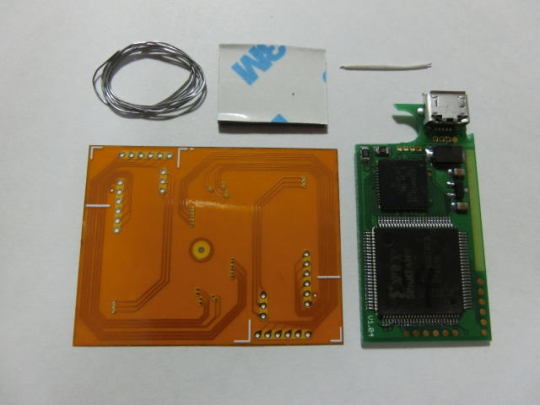
For the sake of documentation, the big chip on the bottom is a XILINX Spartan-3A FPGA (XC3S50A), package type is VQG100 (very thin flat pack), speed grade 4, temp range 0-85 degrees C. On top is a Cypress EZ-USB FX2LP (CY7C68013A) microcontroller, package type appears to be -56-LTXC.
The rest of the stuff on the green board is just a standard Micro-USB-B connector and passives like diodes, capacitors, resistors, and maybe a power regulator or two. The orange paper thing is also a circuit board, the intent is you cut it in a specific way to connect the board to specific electrical pads on the 3DS's circuit board, and the material the orange is made out of is flexible allowing for unique positioning and reaching.

It's definitely a complex piece of tech! The FPGA takes in the video signals from the 3DS, processes them a bit, spits them out to the USB chip which sends them to a PC to be displayed. That's oversimplifying it just a teensy bit.
Unfortunately, due to the FPGA being in use instead of some kind of dedicated circuitry, we can't actually see how the data is being taken in and processed. FPGA's are field programmable gate arrays, meaning they are chips that are given a bit of code that manipulates how their logic works on a physical level, rather than just electronically processing signals. This is all done inside the chip, instead of some dedicated chip that does a specific function or a portion of a circuit board with known parts and gates. Unless we have a preprogrammed FPGA chip on hand and are able to test every single input and what its output would be (or even better, the source code for the FPGA from Optimize), we cannot possibly know how the FPGA takes the input and gives some output.
Luckily, we can make some educated guesses without ever actually owning a board, but rather looking at the software needed to use it!

Enter non-standard, a Japanese maker of stuff. They created the program that interfaces with the 3DS capture cards that are installed by almost all services. The program in question is called `nonstd 3line Differential Signal viewer`, or just n3DSview, referencing the creator's name, the n3DS, and the method of transporting color data from a circuit board to a screen. Basically, differential signaling uses two wires for one bit of data, flipping one on and the other off to represent a one, then the reverse for a zero. This is done for signal integrity, and the 3 pairs mentioned represent red, green, and blue. (Note: this may not be how the video transmit system works for 3DS, this is just what the name is implying)
Now, USB is a complicated thing. When something wants to be transmitted over it in a unique way that isn't defined by some standard (so it's non-standard, hah!) (also, some standard interfaces include things like keyboards, mice, midi devices, and storage devices), one must create and define a device driver. Luckily the software comes with the necessary driver, so let's take a look.

Yep, just as expected, this software relies on the onboard USB chip from Cypress to handle communications. The driver simply provides Windows a name to a face-- er, USB connection. The other files with the driver are the actual communication binaries that Windows uses to understand the incoming and outgoing signals. Unfortunately, due to the nature of the files being bytes and bytes of unintelligible compiled code, we're a bit stuck. We don't actually know how the device is communicating. Lucky for us, Raspberry Pi might have the answer
Linux, like Windows, may need drivers. A Raspberry Pi runs Linux (usually) and needs to be able to communicate with devices just like Windows does. Thus, this file called a shared object file (which is like a Windows DLL) is provided along with the Raspberry Pi version of n3DSview. It contains code that can be used by any program compiled against it to interface with the USB device. It gives us great insight into how the USB chip communicates: through its dedicated FIFO processing!

The image above is from the reference manual for the USB chip (this document also describes the FIFO specs), which describes all of the chips functions and features. FIFO is short for "first in, first out". This means that the data that gets put in first to the FIFO will be the first to get out. Think of it like a line in an amusement park. First arrivals get to get on the ride first, and a line will build up. The data works just like that, ensuring that it gets sent and processed in the correct order.
So we know that the chip is sending processed data in a FIFO manner, but we don't actually know how the signals from the 3DS are processed by the FPGA before they get sent to the USB chip. So we're a bit stuck for now, but we have a lot of great info from just looking at pictures and text. The next step would be to potentially decompile the RPi binary and see how it processes the input from USB, but that'll be for another time.
#nintendo#3ds#capture card#hardware#technology#this is what happens when i have too much time and the ability to google too well#apex barks
2 notes
·
View notes
Link
Resistors are devices, which are used to limit current flow and provide a voltage drop in electrical circuits.
With small size physically, the resistors are marked with color coded bands that have a different number per color, as well as the tolerance of the resistor. The use of color bands on the body of parallel resistors is the most common system for indicating the value of a resistor. Color-coding is standardized by the Electronic Industries Association (EIA).
1 note
·
View note
Text
💥AL'S ELECTRONICS COURSE -ELECTRONIC COURSE -ELECTRONICS COURSE ONLINE -BASIC ELECTRONICS COURSE
youtube
🎯LINK OFFICIAL WEBSITE:https://cutt.ly/alselectronicscourse_official
🔴What will you learn in Al’s electronics course?
-With a Brief History of Electronics -Current Flow, Voltage and Resistance -Introduction of Ohm's Law with several examples explained -Covers the Basics In AC and DC Voltage -AC and DC Current and Current Direction. -Defines the term quantity Ampere also Covers Basic characteristics of Resistance and Explains the Color Code System and the Tolerance System for Fixed Resistors and other Passive Components that provide Resistance in an Electronic Circuit.
🔴The Math section will cover many different Math Topics Related to the Decimal Numbering System.
🔴Al explains the mechanics involved in Addition, Subtraction, Multiplication and Division with both positive and negative numbers' Al explains fractions and decimal fractions along with Algebra basics. Section ends with an introduction to Trigonometry
🔴The Next Section (Circuit Analysis) takes the Student thru Calculating Voltage, Current and Resistance on a Series, Parallel and Series Parallel Circuits! Al gives the student a step by step instruction on how to solve these circuit properties.
🔴After finishing this Electronic course the student should have a very good understanding of Voltage drops, Current Division and Power consumption in a Electronic Circuit.
🔴Advance Circuit Analysis Covers Kirchhoff's Circuit Laws and Network Theorems , Super Position, Thevenin Theorem and Norton Conversions. Al Gives a detailed explanation on each of these Circuit Analysis Techniques.
🔴This Electronic course is Broken into two Sections. Section one is Kirchhoff's Circuit Laws and Section two, network theorems and how they are used to analysis a circuit.
AND MUCH MORE FOR YOU, CLICK ON THE VIDEO AND LEARN MORE
#electronicscourse#electroniccourses#electronicscourseonline#electroniccourseonline#basicelectronicscourse#basicelectronic#basicelectronics#powerelectronicscourse#Alselectronicscourse#Youtube
0 notes
Text
20W 30W 50W Laser Marking Machine Laser Marker
What is Laser Marking Machine?
Laser Marking Machine stands for marking or labeling of workpieces and materials with a laser beam. In this regard, different processes are distinguished, such as engraving, removing, staining, annealing and foaming. Depending on the material and the quality requirement, each of these procedures has its own advantages and disadvantages.
igoldencnc Group has been producing benchmark Fiber Laser Marking Machines. It is the collective and constant work of our highly experienced research scholars, laser specialists, engineers specialized in the fields of software, electrical, mechanical and instrumentation. We give utmost emphasis to the R&D activities that has lead us to bring path-breaking Fiber Laser Marking Solutions. These Laser Engraving & Marking Systems are highly adaptive and excellently capable and have acknowledged globally.
Features of 50W Laser Marking Machine:
1. Small pulse width, small heat residue, no deformation of the substrate, fine and bright white shading
2. Through wide-area parameter settings, different degrees of gray and black processing can be performed
3. By adjusting the pulse width, frequency, power and so on, a variety of color effects can be combined
4. Easy to clean, clear edge contour, better light transmission, high efficiency
5. No hand feeling, not easy to turn yellow, fine processing
6. The carving depth is relatively weak, but the shading is fine and the taper is small, so it can be brightened
7. Small pulse width, small thermal effect, clean tin free, small linewidth, fine resistance regulation
8. With small pulse width and medium frequency, the bar code is clearer, not easy to remove and easy to scan
Laser Marking Machine for Metal Application Materials:
Laser Marking Machine for Metal & Plastics. It can work with most metal marking applications, such as Stainless Steel, Brass, Aluminium, Steel, Iron etc, and can also mark on many non-metal materials, such as ABS, Nylon, PES, PVC, Makrolon.
Laser Marking Machine for Metal Applicable Industries
Electronic Components: Resistors, Capacitors, Chips, Printed Circuit Boards, Computer Keyboard, etc.
Mechanical Parts: Bearings, Gears, Standard Parts, Motor, etc.
Instrument: Panel Board, Nameplates, Precision equipment, etc.
Hardware Tools::Knives, Tools, Measuring Tools, Cutting Tools, etc.
Automobile Parts::Pistons and Rings, Gears, Shafts, Bearings, Clutch, Lights, etc.
Daily Necessities:Handicrafts, Zipper, Key Holder, Sanitary Ware, etc.
Laser Marking Machine Details
📷
📷
📷
UV Marking Machine Labeling Scope of Application
📷
Advantages of Laser Marking Machine:
> No Consumables, Super Long lifespan & Maintenance Free
The Coherent Sealed metal Co2 laser source has super long lifespan of over 40,000 hours without any maintenance. No need to spare any extra consumer parts at all.
Suppose you will work for 8 hours per day, 5 days a week, The laser could work properly for you for more than 5 years without extra costs except electricity. When Run out of the Co2 gas in it, it could be refilled and work again.
> Simple Operation :
Our patent software supports almost all common formats, The operator does not
have to understand programming, Just simply set a few parameters and click start.
> High Speed Laser Marking
The Marking accuracy could reach up to 0.001 mm
while the repositioning accuracy is 0.002mm.
> Multi-functional:
It could Mark/Code/Engrave un-removable serials Numbers, batch Numbers, Expiry info,
Best Before date, logo & any Characters that you want. It could also mark QR code for
promoting activities or product sales district Tracking and Traceability. Helps you to
analysis custom behavior based on BIG DATA TECHNOLOGY.
0 notes