#Guide wire Manufacturers
Text
Exploring the World of Carbide Tooling with Regal Carbide Dies
In the intricate world of manufacturing and metalworking, precision and durability are paramount. Whether it's drawing fine wire for electronics, creating robust machine parts, or ensuring smooth operations in high-speed machining, the quality of the tools used makes all the difference. At the forefront of this precision tooling industry is Regal Carbide Dies, a leading manufacturer providing an array of carbide solutions including wire drawing dies, carbide plugs, carbide dies, carbide-lined collets, and carbide-lined guide bushes.

Wire Drawing Dies Manufacturers
Wire drawing dies manufacturers are crucial in the production of wires with precise diameters and smooth finishes. These tools help in reducing the diameter of wires by drawing them through a series of dies, each progressively smaller than the previous one. Regal Carbide Dies specializes in manufacturing high-quality wire drawing dies that ensure efficiency and longevity. Their expertise in using tungsten carbide and polycrystalline diamond (PCD) guarantees that the dies withstand the high pressures and stresses involved in the wire drawing process, ensuring superior performance and a longer lifespan.
Carbide Plugs Manufacturers
Carbide plugs are essential components used in various industrial applications, including the manufacturing of seamless tubes and the extrusion of metals. Regal Carbide Dies produces carbide plugs manufacturers that offer exceptional wear resistance and toughness. These plugs are designed to endure extreme conditions, ensuring consistent performance and reducing downtime in manufacturing processes. The company's commitment to using top-grade materials and advanced manufacturing techniques ensures that their carbide plugs meet the highest standards of quality and reliability.
Carbide Dies Manufacturers
Carbide dies are indispensable in shaping and forming metals into desired shapes with high precision. Regal Carbide Dies excels in producing carbide dies manufacturers that cater to a wide range of industries, including automotive, aerospace, and construction. Their carbide dies are engineered to deliver precise results, whether used in stamping, extrusion, or cold heading processes. The use of high-quality carbide material ensures that these dies offer excellent wear resistance, maintaining their precision over extended periods of use.

Carbide-Lined Collets
In high-speed machining and precision drilling, carbide-lined collets play a vital role in holding tools firmly in place. Regal Carbide Dies manufacturers carbide-lined collets that offer superior grip and reduced wear, ensuring accurate and stable machining operations. These collets are designed to withstand the high rotational speeds and forces encountered in modern machining processes, providing reliable performance and extending the lifespan of both the collet and the tool.
Carbide-Lined Guide Bushes
Carbide-lined guide bushes are essential components in various machining and manufacturing processes, providing guidance and support to cutting tools and workpieces. Regal Carbide Dies produces carbide-lined guide bushes that offer exceptional durability and precision. These guide bushes are engineered to resist wear and maintain their accuracy even in the most demanding applications. The use of carbide lining ensures that they provide consistent performance, reducing the need for frequent replacements and minimizing downtime.
Conclusion
In the competitive and demanding world of manufacturing, having reliable and high-quality tooling solutions is crucial. Regal Carbide Dies provides an array of carbide products, from wire drawing dies to carbide-lined guide bushes, designed to meet the needs of various industries. Their commitment to excellence ensures that their products not only meet but exceed customer expectations, making them a trusted partner in achieving manufacturing success.
#Wire Drawing Dies Manufacturers#Carbide Plugs Manufacturers#Carbide Dies Manufacturers#Carbide Lined Collets#Carbide Lined Guide Bushes
0 notes
Text
The Benefits of Using PTFE Guide Wire in Medical Procedures
In the ever-evolving landscape of medical technology, innovations like PTFE guide wire have emerged as game-changers, redefining the precision and efficacy of various medical procedures. Polytetrafluoroethylene, commonly known as PTFE, is a synthetic fluoropolymer of tetrafluoroethylene and boasts a unique set of properties that make it an ideal material for guide wires used in medical interventions.
At the heart of PTFE's efficacy is its exceptional lubricity. This property facilitates smooth navigation through intricate anatomical structures, reducing friction and allowing for enhanced maneuverability. In procedures that demand intricate pathways, such as vascular interventions or catheter placements, the lubricity of PTFE guide wires plays a pivotal role in ensuring precision and minimizing the risk of damage to delicate tissues.
PTFE's inherent biocompatibility makes it a preferred choice in medical applications. Biocompatible materials are designed to interact harmoniously with the human body, minimizing the risk of adverse reactions. PTFE guide wires, being biocompatible, offer a reduced likelihood of inflammation, irritation, or rejection, making them suitable for a wide range of medical procedures without compromising patient safety.
Medical procedures often rely on real-time imaging to guide practitioners. PTFE's radiopacity enhances visibility under fluoroscopy and other imaging modalities, allowing for the precise placement of guide wires. This feature is especially critical in interventions where accuracy is paramount, such as cardiac catheterization or endovascular procedures.

PTFE's resistance to chemicals and high temperatures adds another layer of reliability to its application in medical procedures. This resistance ensures that the guide wires maintain their structural integrity even when exposed to the harsh conditions of certain medical interventions, contributing to their longevity and overall effectiveness.
The versatility of PTFE guide wires is evident in their applicability across various medical specialities. From cardiovascular interventions to neurovascular procedures, PTFE guide wires demonstrate their adaptability and reliability in navigating the intricate pathways of the human body.
Manish Medi Innovation: Pioneering the Future of Medical Technologies
As a trailblazer in the field of medical innovations, Manish Medi Innovation stands at the forefront of integrating cutting-edge technologies to enhance healthcare outcomes. Our commitment to excellence is reflected in the development and promotion of advanced solutions like PTFE guide wires.
In the dynamic landscape of healthcare, precision and safety are paramount. PTFE guide wire, with their unique set of properties, have emerged as indispensable tools in modern medical procedures. At Manish Medi Innovation, we take pride in being at the forefront of this medical revolution.
Our dedication to advancing healthcare technologies is unwavering. When you choose Manish Medi Innovation, you're not just opting for state-of-the-art products; you're choosing a partner in progress. As we continue to pioneer the future of medical technologies, trust us to provide you with tools that elevate the standards of care, ensuring a healthier and more promising tomorrow.
1 note
·
View note
Text
Navigating Precision and Flexibility: Exploring the World of PTFE Guide Wires
In the medical industry, where precision and flexibility are paramount, PTFE guide wires play a crucial role. These remarkable tools are used extensively in minimally invasive procedures, guiding catheters and other medical devices through blood vessels and different narrow pathways with unmatched accuracy. As a leading provider of high-quality PTFE guide wires, Flexotech Mysore is proud to delve into the world of these innovative devices, shedding light on their composition, applications, and the critical role they play in modern medical practices.
Understanding PTFE Guide Wires: Paving the Way for Minimally Invasive Procedures
PTFE, short for polytetrafluoroethylene, is a synthetic fluoropolymer with remarkable properties, including high temperature resistance, excellent chemical resistance, and an ultra-smooth surface. These unique characteristics make PTFE an ideal material for medical guidewires used in a variety of interventional procedures. PTFE guide wires are thin, flexible, and highly manoeuvrable, allowing physicians to navigate intricate anatomical structures precisely and easily.
Key Characteristics of PTFE Guide Wires

Flexibility: PTFE guide wires are known for their exceptional flexibility, allowing physicians to navigate tortuous blood vessels and challenging anatomies with reduced risk of vessel damage. The flexibility of these wires is critical for ensuring safe and successful procedures.
Low Friction Coefficient: PTFE's ultra-smooth surface provides a low friction coefficient, enabling effortless advancement of the guide wire through vessels. This feature minimizes the risk of vascular injury and improves patient comfort during procedures.
Radiopacity: In many interventional procedures, it is essential to visualize the guide wire's position under fluoroscopy or X-ray. PTFE guide wires can be enhanced with radiopaque markers, making them visible under imaging, thereby facilitating accurate navigation.
Steerability: PTFE guide wires often have a tapered or hydrophilic coating at the tip, which enhances steerability and facilitates smooth advancement through tortuous vessels. This property enables precise navigation even in challenging anatomies.
Compatibility: PTFE guide wires are compatible with various medical devices and catheters used in interventional procedures, making them versatile tools for a wide range of applications.
Applications of PTFE Guide Wires in Medicine
PTFE guide wires are widely used in various minimally invasive medical procedures, including:
Cardiac Catheterization: In coronary angioplasty and stent placement procedures, PTFE guide wires guide catheters through the coronary arteries, enabling precise positioning of devices to treat blockages.
Peripheral Arterial Interventions: PTFE guide wires aid in treating peripheral arterial diseases, such as atherosclerosis, by navigating through blood vessels in the legs, arms, and other peripheral areas.
Neurovascular Interventions: In neuroendovascular procedures, PTFE guide wires are vital in navigating through delicate cerebral vessels to treat conditions such as cerebral aneurysms and arteriovenous malformations (AVMs).
Urology: PTFE guide wires are used in urological procedures to access and treat obstructions and stones in the urinary tract.
Gastroenterology: In endoscopic procedures, PTFE guide wires help navigate through the digestive tract, assisting in the placement of stents and other therapeutic devices.
Advantages of PTFE Guide Wires in Minimally Invasive Procedures
The use of PTFE guide wires offers several significant advantages:
Reduced Trauma: PTFE's low friction coefficient reduces the risk of trauma to blood vessels and surrounding tissues during navigation, leading to safer procedures and faster patient recovery.
Enhanced Precision: The exceptional flexibility and steer ability of PTFE guide wires allow physicians to access difficult-to-reach areas with precision, improving the success rate of procedures.
Minimized Radiation Exposure: The enhanced visibility of radiopaque PTFE guide wires reduces the need for prolonged fluoroscopy, minimizing radiation exposure to patients and medical personnel.
Smooth Tracking: The smooth surface of PTFE guide wires allows them to glide smoothly through vessels, facilitating easier and faster tracking.
Quality and Safety Considerations
Given the critical nature of medical procedures where PTFE guide wire are used, it is essential to prioritize quality and safety. When choosing PTFE guide wires, medical professionals and healthcare facilities must ensure that the wires meet relevant industry standards and regulatory requirements. Partnering with trusted and reputable suppliers, like Manish medi, is crucial to obtaining high-quality PTFE guide wires that deliver consistent performance and reliability.
Conclusion
In minimally invasive medical procedures, PTFE guide wires are indispensable tools, paving the way for precision and flexibility. Their exceptional characteristics, including flexibility, low friction, radiopacity, steer ability, and compatibility, make them invaluable in various medical applications. With PTFE guide wires, physicians can easily navigate complex anatomies, ensuring safe and successful patient outcomes.
At Manishmedi , we take pride in offering high-quality PTFE guide wires meticulously designed and manufactured to meet the demands of modern medical practices. Our commitment to excellence supports healthcare professionals in providing optimal patient care through cutting-edge medical devices. Contact us today to explore our range of PTFE guide wires and other medical solutions.
0 notes
Link
Get high quality guide wires manufacturers from the leading surgical instrument manufacturers, Niko tech pvt. Ltd. Call now for more details.
0 notes
Text
Yeah, I worked on The Machine. And, as I pried open its secret compartments and loosened its wiring harness and decrypted its memories, it worked on me also. Deep within its many hidden copses lay immense knowledge, unknown to all but those who formed it. Who built The Machine? No one knows. Everyone knows. I know. Now that The Machine works again, the person who last built it was me.
For years, I was a humble regular home-gamer mechanic. Something around the house would break. For the sake of argument, we'll use as an example the time my microwave blew up when I opened the door. One morning, it just went pop and never worked again. Well, at least until I fixed it. It turns out that the door had a little microswitch inside, and that microswitch got gummy with aerosolized food goo. Because it was gummed up, it wouldn't switch the computer off in time when I opened the door. That would be dangerous: I could get a full face shot of microwaves from the still-running magnetron. A safety interlock fired, and blew the brains out of the big fuse controlling the magnetron. It died for me. Replacing the switch, and the fuse, brought that microwave back to life. I did many such repairs. I was not prepared for this repair.
Fix after fix, I built up my confidence, and I got cockier. I'd pull broken machines out of the trash, mysterious foreign computers from another country. Some things escaped my grasp, and slipped further into oblivion. Most, though: most, I pulled back from the brink, and forced them to live again. That's when I found The Machine.
It was beautiful, intricate: thousands of parts, wedged together tighter than I had ever seen before, and a cryptic fault at the centre of it. When you cram together this much stuff, the complexity doesn't just add: it multiplies. To aid me, I looked for a guide, a factory service manual. The manufacturer laughed. The manufacturer's representative laughed. Someone who made it, who I tracked down on LinkedIn, hung up on me and refused to answer his door when I visited. Weeks later, he was gone, "dead" in a suspiciously convenient accident, a body left behind at the edge of his bleach-washed property with no identifying marks or fingerprints. I got the message: I was on my own.
This little wire just came unplugged. I guess someone must have dropped it. All better now.
2K notes
·
View notes
Text
For anyone who’s already seen Boy and the Heron i found this really interesting article where Ghibli Boss/Producer Suzuki was interviewed recently by indie wire and explains the background of the characters from the new Ghibli film, I’ve copied the full article below or you can click the link to go to the interview but once again it contains so many spoilers
‘The Boy and the Heron’ Is So Personal, Hayao Miyazaki Needed a Year to Grieve Before Pivoting in a New Direction
Miyazaki came out of retirement for his first film in a decade, about his friendships at Ghibli with the late co-founder/director Takahata and co-founder/producer Suzuki.
When Hayao Miyazaki pitched “The Boy and the Heron” (GKids, now in select L.A. and NYC theaters) to Studio Ghibli co-founder/producer Toshio Suzuki in 2016, he asked permission to make the story about himself. This took Suzuki — his friend of nearly 40 years at the time — by surprise; the legendary anime director isn’t known for getting so personal. And yet this aligned perfectly with the notion that Ghibli films are devoted to reliving memories.
“I agree that it is Miyazaki’s most personal film because he actually told me,” Suzuki told IndieWire over Zoom through an interpreter. Not only is “The Boy and the Heron” inspired by Miyazaki’s childhood (he endured the firebombing of Japan during World War II and his father was director of the family’s aircraft manufacturing factory), but also his career at Ghibli with his two closest friends: the late studio co-founder/director Isao Takahata (“Grave of the Fireflies”) and Suzuki.
“Miyazaki is Mahito [the 12-year-old protagonist voiced by Luca Padovan in the English-language version], Takahata is the great uncle [voiced by Mark Hamill], and the gray heron [voiced by Robert Pattinson] is me,” Suzuki added. “So I asked him why. He said [Takahata] discovered his talent and added him to the staff. I think Takahata san was the one who helped him develop his ability. On the other hand, the relationship between the boy and the [heron] is a relationship where they don’t give in to each other, push and pull.”
Collectively, it’s a lot to unpack: Miyazaki came out of retirement for the second time after “The Wind Rises” (2013) to make his 12th feature — the semi-autobiographical, hand-drawn fantasy for his grandchildren. It’s about destruction, loss, and rebuilding a better future through imagination, inspired by the novel he adored as a child (“How Do You Live?”).
Mahito loses his mother in the firebombing of Japan and relocates to the countryside, where his father (voiced by Christian Bale), who runs an air munitions factory, marries his sister-in-law, Natsuko (voiced by Gemma Chan). Traumatized, angry, and confused, the boy encounters a talking heron (part bird, part man), who tells him that his mother is still alive and guides him to an alternate world in a magical tower shared by the living and the dead. There he encounters his great uncle, the architect of the tower, and reunites with both his mother (voiced by Karen Fukuhara) and Natsuko.
At first, Suzuki resisted green-lighting “The Boy and the Heron” because of Miyazaki’s age (he’s 82) and the great expense (it is arguably Japan’s most expensive film but has made the equivalent of nearly $80 million at the country’s box office). Yet Miyazaki wore down his resistance with his enthusiasm and impressive storyboarding. The film took seven years to complete, and Suzuki needed to hire some of Japan’s most talented animators outside of Ghibli to handle the task (including supervising animator Takeshi Honda of “Neon Genesis Evangelion” fame). With diminished stamina and failing eyesight, Miyazaki was unable to oversee the production in the same manner as when he was at the height of his creative powers and relied on Honda to draw, redraw, and review under close advisement.
But with the death of Takahata in 20018, a grief-stricken Miyazaki was forced to scale back the role of the great uncle in the story, who had previously been more central to the boy’s life. “After Takahata passed away, he wasn’t able to continue with that story, so he changed the narrative and it became the relationship between the boy and the Heron,” Suzuki continued. “And in his mind, initially, the Heron was something that symbolizes the eeriness of the mansion and that tower, even ominous, that he goes to during war time. But he changed it to this sort of budding friendship between the boy and the Heron.”
Miyazaki first toyed with the idea of exploring the theme of friendship in “The Wind Rises” (inspired by real-life fighter design engineer Jiro Horikoshi during World War II) before abandoning it. “So this time around, when the Heron became the centerpiece of the story, and he came with the storyboards, I was careful for him to not portray me in a bad way,” Suzuki said. “Having said that, I’ve known Miyazaki for 45 years. I remember everything about him. There are things that only I know. There are things that only the two of us know. And he remembers all these small details, which I was very impressed with.”
For example, when Mahito and the Heron sit and chat at the house of Kiriko (voiced by Florence Pugh), a younger, seafaring version of one of the old maids, it is a recreation of the way Miyazaki and Suzuki would meet. “The place that we do our meetings, where we have our conversation is at his studio, his atelier,” he added. “And he has this like large table, but we don’t sit facing each other, we sit next to each other, and we never look at each other when we talk. And what we discussed was very similar.”
During production, Suzuki became impatient to see the new storyboards with the great uncle. It seemed Miyazaki was intentionally stalling while grieving about Takahata. “My question was: ‘So when is the great uncle going to appear?'” said Suzuki. “He built this great character, but he never appears in the storyboards that he would bring me. But it took him actually about a year after the passing of Takahata that he was able to draw that character into the storyboards in the second half of the story.
“And the most surprising thing for me was when I saw the storyboard where Mahito was asked by his great uncle to carry on with this work, this legacy, and he says no — he declines the offer. Miyazaki was someone who followed the path of Takahata for so many years, and I thought it was a huge thing for him [to follow a different path].”
Meanwhile, Suzuki confirmed that Miyazaki has not retired. The film has given the director renewed confidence to keep working on other stories. However, Miyazaki can’t focus on new ideas while “The Boy and the Heron” remains in theaters. “He needs to empty his mind again,” Suzuki said, “and then when he’s emptied his mind with a blank canvas, he usually comes up with new ideas. So we have to wait a little more.”
894 notes
·
View notes
Text


Finished the HG Michaelis kit. The CFK-029 Michaelis was manufactured by the Grassley Defense Systems and is piloted by Shaddiq Zenelli. Unlike most Mobile suits this unit is strictly short and close combat fighting unit with an its right arm Beam Bracer a multi functional weapon system that can both fire beam attacks or use beam energy to form a beam saber. It can detach in a wire guided attack mode. With the jaws opened the weapon it deploy an anti-permit field that nullifies the use of the data storms as a Gundam counter mechanism. While it’s left arm is a fixed shield and beam saber
This kit was tons of fun to build. And has a lot more of great mobility. As you can tell by the picture I had a lot of fun posing this guy. I am glad I have a second kit of this guy that I intend to use as my first custom designed unit. But that project is a while off.
#gunpla#mech#model kit#plastic model#gundam#g witch#the witch from mercury#high grade#witch from mercury#Grassley#Grassley Denfince systems#shaddiq zenelli#shaddiq#CFK-029#Michaelis
55 notes
·
View notes
Note
Hello! (@saints-who-never-existed here, otherwise unable to reply/message properly due to this being a side-blog)
First of all, just wanted to say that I'm a big fan of the work you've been doing on examining and decoding the Peglar Papers. Absolutely outstanding stuff! <3
Secondly, I hope you don't mind me offering my (entirely unsolicited but professional!) two cents on your post regarding pencil lines on the page with the Open C poem?
In short, I'd like to raise the opinion that the lines we're seeing on the paper may not be pencil lines but 'chain' lines from the paper production process. Wider-spaced 'chain' lines and narrower 'laid' lines come from the wire mesh on which the paper was made (typically a feature of handmade paper but by this point in history it would've been possible to produce them mechanically).
Either way, it certainly does appear that Peglar/Armitage/the author did utilise the lines to keep their writing neat. :D
Anyway, do with that information what you will and feel free to ignore. Just thought it might be of interest to you and this seemed the best way to communicate it. <3
OHHHHH this is fascinating and so appreciated actually!! 🖤🖤🖤 I’m always ready to hear other ideas about this wallet I think about it constantly and love to see other interpretations
the only reason I assumed they were pencil marks at first is because the rondel / “terror camp clear” circle does seem to meeee to be traced out in pencil? which may have very likely been a circle compass (which would make sense to be on a navy ship), or maybe he traced around the diameter of a cup or something similarly round, so I had assumed the use of pencil marks as a sketch/guide would have been applicable on other sheets too… i hadn’t even considered they were part of the actual page’s manufacturing process but that’s such a smart insight omg!!!! ok my overly romantic idea cancelled, this feels so much more likely
6 notes
·
View notes
Text
Engine Repair Instruction Full Guide
Engines are the heart of any vehicle, powering everything from your daily commute to long road trips. Knowing how to repair an engine can be a game-changer, whether you're an enthusiast who loves getting your hands dirty or someone looking to save money on mechanic bills. This guide will walk you through the entire process of engine repair, from diagnosing problems to reassembling your engine and ensuring it runs smoothly.

Understanding the Basics of an Engine
Before diving into the repair process, it’s crucial to understand how an engine works. Most vehicles use an internal combustion engine, which combines fuel and air, ignites it, and transforms that explosion into mechanical energy.
Components of an Internal Combustion Engine
The main components include:
Cylinder Block: The engine's core where combustion occurs.
Cylinder Head: Houses the valves and spark plugs.
Pistons: Move up and down to create the force needed to turn the crankshaft.
Crankshaft: Converts the pistons' up-and-down movement into rotational motion.
Camshaft: Controls the opening and closing of the valves.
Valves: Regulate the flow of fuel and air into the engine and exhaust gases out.
How an Engine Works: A Simple Explanation
An engine works by pulling in a mixture of air and fuel, compressing it, igniting it with a spark (in gasoline engines), and then expelling the exhaust gases. This cycle—intake, compression, power, and exhaust—happens in each cylinder and repeats hundreds of times per minute.
Tools and Equipment Needed for Engine Repair

Whether you're performing a basic repair or diving into more complex work, having the right tools is essential.
Essential Tools for Basic Repairs
Socket Set: For removing and tightening bolts.
Wrenches: Different sizes for various engine parts.
Screwdrivers: Flathead and Phillips for screws and clips.
Pliers: For handling wires and small parts.
Torque Wrench: Ensures bolts are tightened to the correct specifications.
Specialized Equipment for Advanced Engine Work
Engine Hoist: For removing the engine from the vehicle.
Cylinder Hone: Prepares cylinders for new piston rings.
Compression Tester: Checks the health of each cylinder.
OBD-II Scanner: Diagnoses engine codes and issues.
Safety Gear and Precautions
Gloves: Protect your hands from cuts and chemicals.
Safety Glasses: Shield your eyes from debris.
Work Boots: Offer protection against heavy parts or tools.
Diagnosing Engine Problems
Accurately diagnosing engine problems is the first step in any repair process. Understanding the symptoms can save time and prevent unnecessary work.
Common Symptoms of Engine Issues

Check Engine Light: Indicates a problem detected by the car's computer.
Strange Noises: Knocking, tapping, or grinding sounds can signal internal damage.
Excessive Smoke: Blue smoke might mean burning oil, while white could suggest a coolant leak.
Loss of Power: Often linked to fuel or air delivery issues.
Step-by-Step Diagnostic Process
Listen and Observe: Note any unusual sounds, smells, or behaviors.
Check Engine Light Codes: Use an OBD-II scanner to retrieve error codes.
Perform Compression Test: Assesses the health of your engine’s cylinders.
Inspect Fluids: Look for contamination or leaks in oil, coolant, and other fluids.
Step-by-Step Guide to Reassembly
Prepare Your Workspace: Ensure that your workspace is clean, organized, and well-lit. Lay out all the parts and tools you'll need in the order of reassembly. Keep the engine manual handy for specific torque specs and sequences.
Install the Crankshaft: Place the crankshaft back into the engine block, ensuring it is seated correctly. Use assembly lube on the main bearings to prevent damage during the initial startup. Torque the main caps to the manufacturer's specifications.
Insert the Pistons: Install the pistons and connecting rods. Be sure to align the piston rings correctly and use a ring compressor to insert the pistons into the cylinder bore. Attach the connecting rods to the crankshaft and torque the rod bolts to spec.
Install the Camshaft and Timing Components: If your engine uses a timing chain or belt, install it according to the timing marks on the camshaft and crankshaft gears. This step is crucial for ensuring the engine's valves open and close at the correct times.
Attach the Cylinder Head: Place the cylinder head gasket on the engine block, followed by the cylinder head. Torque the head bolts in the correct sequence and to the proper specifications. This ensures a good seal and prevents head gasket failure.
Install Valves, Lifters, and Pushrods: If applicable, install the engine's valves, lifters, and pushrods. Make sure they are properly aligned and that the lifters are seated correctly in their bores.
Reassemble the Valve Train: Install the rocker arms and adjust the valve lash according to the engine manual. Proper valve lash is critical for engine performance and longevity.
Reattach External Components: Begin reattaching external components like the water pump, oil pump, timing cover, oil pan, and intake manifold. Replace any gaskets and seals during this process to prevent leaks.
Reconnect the Fuel and Ignition Systems: Reinstall the fuel injectors, spark plugs, and ignition wires. Ensure all electrical connections are secure and properly routed to avoid short circuits or malfunctions.
Final Checks: Before moving on, double-check all connections, bolts, and components. Make sure nothing is left loose or unconnected.
Applying Proper Torques and Specifications
Every engine has specific torque settings for each bolt. Over-tightening can strip threads or warp components, while under-tightening can lead to leaks or parts coming loose. Use a torque wrench and follow the manufacturer's specifications closely.
Double-Checking Work for Mistakes

It's easy to miss a step or make a mistake during reassembly. Double-check your work:
Ensure all components are installed in the correct order.
Verify all bolts are torqued to spec.
Check for any leftover parts or tools in the engine bay.
Testing the Repaired Engine
With the engine reassembled, the next step is testing it to ensure everything is functioning properly.
Preparing for Initial Startup
Before starting the engine, perform a few preparatory checks:
Prime the oil system: This can be done by cranking the engine with the fuel system disabled until oil pressure is achieved.
Fill the engine with fresh oil and coolant.
Double-check all electrical connections and fuel lines.
Checking for Leaks and Unusual Noises

Once you start the engine, pay close attention to any unusual noises or leaks:
Oil Leaks: Check around the oil pan, valve covers, and front and rear seals.
Coolant Leaks: Inspect the radiator, hoses, and water pump area.
Unusual Noises: Listen for knocking, tapping, or whining sounds, which could indicate an issue with the timing components or internal parts.
Fine-Tuning and Adjusting the Engine
After the initial startup, the engine may require some adjustments:
Timing Adjustments: Use a timing light to set the ignition timing.
Idle Speed: Adjust the idle speed according to the manufacturer’s specifications.
Fuel Mixture: On carbureted engines, you may need to adjust the air-fuel mixture for optimal performance.
Common Engine Repair Mistakes to Avoid
Engine repair is complex, and mistakes can be costly. Here are some common errors to watch out for:
Misalignments and Incorrect Torques
Misaligned timing components can lead to poor engine performance or damage.
Incorrectly torqued bolts can cause leaks, parts failure, or engine damage.
Overlooking Small Parts and Connections
Small parts like washers, clips, or gaskets are easy to overlook but crucial for preventing leaks and ensuring proper function.
Electrical connections: Double-check that all sensors and connectors are properly seated.
Skipping Diagnostic Steps
Skipping steps in the diagnostic process can lead to unnecessary repairs or missed issues. Always perform thorough diagnostics before and after repairs.
Maintaining Your Engine After Repair
Proper maintenance is key to ensuring the longevity of your newly repaired engine.
Importance of Regular Maintenance
Regular maintenance, such as oil changes, air filter replacements, and coolant checks, is essential to keep your engine running smoothly and prevent future problems.

Tips for Extending Engine Life
Use high-quality oil and filters.
Avoid hard driving until the engine is fully warmed up.
Regularly check and maintain fluid levels.
When to Seek Professional Help
While DIY repairs can save money, some issues are best left to professionals, especially if you encounter complex problems or lack the necessary tools and expertise.
Dealing with Advanced Engine Repairs
Some engine repairs are too complex for the average DIYer. Here's when to consider professional help:
Understanding When It’s Beyond DIY
Extensive internal damage: Cracked blocks or severely worn bearings usually require professional expertise.
Advanced electrical issues: Problems with engine management systems often need specialized diagnostic tools and knowledge.
Overview of Complex Repairs: Timing Belt, Engine Rebuilds
Timing Belt Replacement: Involves precise alignment of engine components and is critical for preventing engine damage.
Engine Rebuilds: This is a time-consuming and complex task that often requires professional machining and specialized tools.
Working with a Professional Mechanic
When the repair is beyond your capabilities, working with a professional mechanic ensures that the job is done correctly and safely. They have the tools, experience, and resources to handle complex engine repairs.
Cost Considerations in Engine Repair
Engine repair costs can vary widely depending on the scope of work, parts required, and whether you do it yourself or hire a professional.
Estimating Costs for DIY vs Professional Repair
DIY Repairs: Typically cost less but require an investment in tools and time.
Professional Repairs: Can be expensive but come with the assurance of experience and often a warranty.
Budgeting for Tools, Parts, and Time
Consider the cost of any special tools or equipment you might need, as well as the cost of replacement parts. Factor in the time required, especially if the vehicle is your daily driver.
Understanding the Cost of Mistakes
Mistakes can be costly. Stripping a bolt, breaking a part, or incorrect assembly can lead to additional expenses. Always weigh the risks before starting a major repair.
Conclusion
Recap of Key Points
Engine repair is a rewarding but challenging task that requires careful planning, the right tools, and attention to detail. Whether you’re fixing a minor issue or performing a complete rebuild, following the correct procedures is crucial for success.
Encouragement for DIY Enthusiasts
For those who love working on their vehicles, engine repair can be a satisfying and cost-effective way to maintain your car. With patience and persistence, even complex repairs can be tackled with confidence.
Final Thoughts on Engine Repair
Always approach engine repair with a clear plan and the right resources. Don’t hesitate to seek professional help when needed, and remember that regular maintenance is the best way to avoid major repairs.
FAQs
How do I know if my engine needs repair?
Common signs include unusual noises, excessive smoke, loss of power, and a check engine light. Regular diagnostics can help catch issues early.
Can I repair my engine without professional help?
Basic repairs like replacing gaskets or sensors can often be done at home with the right tools. However, more complex tasks like engine rebuilds may require professional expertise.
What are the signs of a failing engine?
Signs include knocking noises, excessive oil consumption, smoke from the exhaust, and persistent overheating.
How long does it take to repair an engine?
The time required varies greatly depending on the complexity of the repair. Simple repairs might take a few hours, while a full rebuild could take several days or longer.
2 notes
·
View notes
Text
open to all —crossovers & ocs welcome
"Welcome to the Museum of London! I'm Tom Natsworthy, and I will... I will be your guide today! I suppose."
Tom grinned and rolled excitedly up onto the balls of his feet, his hands folded neatly behind his blue Historian's coat as he addressed the museum's newest visitor. He was only an Apprentice Historian (and a lowly Third Level at that), but he was fortunate today; their unexpected guest had come at an off hour when all the other Historians in the guild had long gone home. Technically, he shouldn't be there either, because technically the museum was closed, but he was, and so was this visitor, and he could hardly let them poke around on their own without guidance or supervision. So naturally that left him to do the big Senior Historian Duty of guiding, and showing, and telling (all three of which he believed he could do very well if only anyone gave him the chance to, thank you very much).
Another little bounce. Tom cleared his throat and swept his arm ahead of them. "Well! Shall we get started, then?"
The Museum of London was expansive, one of the largest among all of the predator cities, Tom expected. From natural science to mysterious Old World tech, they had it all. Grand displays of ancient mummified animals in glass cases stood against the tall, stone walls and birds of all sorts (some taxidermy, some merely manufactured depictions of what they believed such creatures must have looked like) hung from the arched ceiling and swayed gently with London's movements. Tom pointed them out as they went, explaining the what, where, and when of each creature: This is what the Ancients called a 'bear', specifically a 'pan-da', which once roamed parts of Shan Guo before the Sixty Minute War... This was known as an elfant... This was a tiger... This was a massive, man-eating lizard mysteriously called a croc o' dials which used its great prehensile tail to... And so on, and so on. Each animal he presented with a muted, fidgeting sort of enthusiasm, as if struggling to strike a balance between professionalism, genuine interest, anxiety, and his delight at finally being able to play tour guide. But no exhibit seemed to fill young Apprentice Tom Natsworthy with quite as much glee as the one he brought them to next:
"...and this gorgeous creature is the blue whale. The most magnificent megafauna of the ancient world and one of the Museum's most impressive archaelogical discoveries!" Tom spread his arms wide. The exhibit was in part real skeletal remains from the tail to just behind the blow hole, and from blow hole to its broad, smiling face, it was painted fabrics and leathers, carefully stretched over a... mostly accurate wire sculpt. "Recent discoveries suggest that the blue whale was not, in fact, the scourge of the deep seas as previously thought. Instead, we believe it survived largely on a diet of small fish, sea insects, and salt, which it either pulled from the ocean's water or harvested from stones at the floor. The blue whale is a living— erh," Tom flushed pink, "was a living example of a gentle giant. My personal favourite, if I'm honest."
Still looking a touch embarrassed, Tom cleared his throat.
"Anyway! Those are the Natural Science highlights," he said. "Down that way we have Old Tech of the Ancients, and to the left there... Art of the Ancients, which, um, includes a small section for Old World gods, if you're interested, but... Well. Enough of my blabber, do you have any questions?"
#i had to get this out of my system skdfls#mortal engines rp#doctor who rp#scifi rp#steampunk rp#me rp#dw rp#i hope you don't mind me dropping this in the dw tag; i just think they'd crossover nicely
7 notes
·
View notes
Text
How to Transform Your Smartphone with a DIY Smart Ink Screen Phone Case

Click here: https://amzn.to/45r4SVe
Imagine a phone case that does more than just protect your device. A case that turns your phone into a canvas, allowing you to customize and update your display whenever you desire. Welcome to the world of Smart Ink Screen phone cases. Here’s how you can create your very own DIY Smart Ink Screen phone case and take your phone to the next level.
The Revolutionary Concept of Smart Ink Screens
Smart Ink technology, also known as E Ink, is transforming how we interact with our devices. Unlike traditional LCD or OLED screens, E Ink screens consume less power, are easily readable in sunlight, and provide a paper-like reading experience. This makes them ideal for a multitude of applications, including phone cases.
Why DIY?
Why settle for a mundane phone case when you can craft something extraordinary? A DIY Smart Ink Screen phone case not only adds a touch of personal flair but also serves as a functional extension of your device. Whether you want to display notifications, a to-do list, or your favorite artwork, the possibilities are endless.
What You Need
Creating your own Smart Ink Screen phone case is simpler than you might think. Here’s what you’ll need:
1. A Smart Ink Display Module: Choose a screen size that fits your phone model.
2. Microcontroller: To control the display and connect it to your phone.
3. Power Source: A small, rechargeable battery pack.
4. Phone Case: Preferably one that’s easy to modify.
5. Tools: Screwdrivers, soldering iron, and adhesive.
Step-by-Step Guide
Choose the Right Smart Ink Screen
Start by selecting a Smart Ink display module that is compatible with your phone’s dimensions. Look for one with good resolution and contrast.
2. Prepare the Phone Case
Carefully measure and cut out a section of the phone case where the Smart Ink screen will be placed. Ensure the cut-out is precise to avoid any gaps or misalignment.
3. Assemble the Components
Solder the microcontroller to the Smart Ink screen following the manufacturer’s instructions. Connect the power source to the microcontroller. Test the setup by loading some basic images or text to ensure everything works correctly.
4. Secure the Screen
Attach the Smart Ink screen to the phone case using a strong adhesive. Make sure it is firmly in place but not so tight that it risks damage.
5. Final Integration
Place the assembled components into the phone case. Tuck the wires neatly to avoid any obstruction or bulkiness. Double-check all connections and the screen’s visibility.
6. Personalize Your Display
Once everything is set up, you can start personalizing your Smart Ink screen. Use dedicated apps to update the display with images, notifications, or even your favorite quotes. The low power consumption of E Ink means your phone case display will last for days on a single charge.
The Benefits
• Customization: Change your display whenever you like.
• Battery Efficiency: Smart Ink screens use minimal power.
• Readability: Perfect for outdoor use with clear visibility in sunlight.
• Innovation: Stand out with a unique, functional phone case.
Make It Yours
Creating a DIY Smart Ink Screen phone case is more than just a fun project; it’s a way to express your individuality and innovation. With a bit of creativity and some basic tools, you can transform your ordinary phone case into something extraordinary.
Ready to start your DIY journey? Enhance your smartphone experience today. Click here to find all the tools and components you need to create your own Smart Ink Screen phone case.
By embracing this cutting-edge technology and combining it with your personal touch, you’ll not only protect your phone but also turn it into a dynamic and interactive accessory. Dive into the world of DIY and let your phone case speak volumes about who you are.
Link https://amzn.to/45r4SVe
2 notes
·
View notes
Text
Powering the Future of Railways: A Comprehensive Guide to Connectors for Railway Traction
In the context of global advancements towards sustainable and efficient transportation alternatives, there is a notable resurgence in the prominence of railways. The utilisation of railways as a primary means of transportation for both passengers and freight is on the rise, mostly due to the advantageous environmental attributes and cost-efficiency associated with this method of transport. The complex technology that drives modern railway systems is crucial for their performance, with a key element being the connectors employed for railway propulsion. Reliability you can depend upon. Elevate your railway systems with premium railway traction connectors manufactured and supplied by Radiant Enterprises - one of the distinguished Railway Traction Connectors manufacturers in India!

This thorough guide aims to provide an in-depth analysis of railway traction connectors, examining their importance, various types, advantages, and potential prospects in the future. A comprehensive grasp of these connectors is imperative for individuals engaged in the railway sector, as they assume a crucial function in propelling the advancement of trains and cultivating an environmentally friendly transportation infrastructure.
The Importance of Railway Traction Connectors:
This thorough guide aims to provide an in-depth analysis of railway traction connectors, examining their importance, various types, advantages, and potential prospects in the future. A comprehensive grasp of these connectors is imperative for individuals engaged in the railway sector, as they assume a crucial function in propelling the advancement of trains and cultivating an environmentally friendly transportation infrastructure.
Types of Railway Traction Connectors:
· Pantographs:
Pantographs represent the prevailing form of connectors employed in electric trains. The pantographs, located on the train's roof, establish a connection with the overhead wires, facilitating the transfer of electrical power to the train. Contemporary pantographs are outfitted with advanced sensors and control systems, enabling them to adjust to fluctuating voltage levels and maintain a consistent power provision.
· Third Rail Collectors:
The utilisation of a third rail as a power source is observed in certain railway systems, where trains derive electrical energy from an additional rail positioned adjacent to the tracks. Third-rail collectors are dynamic connectors that establish an electrical connection by sliding and making contact with the third rail. This approach is commonly observed in specific urban transport networks owing to its straightforwardness and economical nature.
Benefits of Advanced Railway Traction Connectors:
· Enhanced Efficiency:
Contemporary connections utilised in railway traction systems are engineered with the objective of minimising power losses during gearbox, hence leading to enhanced energy efficiency. The achievement of efficient power transmission results in a decrease in energy consumption and a reduction in operating expenses for railway operators.
· Reliability and Safety:
The utilisation of premium materials and cutting-edge engineering in the production of connectors guarantees a dependable and secure electrical linkage, hence enhancing reliability and safety. This improves the dependability and security of railway operations, hence mitigating the likelihood of power disruptions and incidents.
· Reduced Maintenance:
Connector designs that are more advanced sometimes possess self-cleaning capabilities, hence aiding in the prevention of the accumulation of dirt, debris, and ice on the contact surfaces. The implementation of this self-cleaning technology results in a reduction in maintenance demands and a decrease in downtime, hence enhancing operational availability.
· Sustainability:
The utilisation of electric trains, which are fueled by renewable energy sources, plays a substantial role in mitigating greenhouse gas emissions and addressing the issue of climate change. The utilisation of high-quality traction connectors is of paramount importance in expediting the acceptance and implementation of sustainable transportation systems.
The Future of Railway Traction Connectors:
The ongoing progress of technology will inevitably lead to the further development of railway traction connectors. Transform railway electrification with the advanced Railway Traction Connectors supplied by Radiant Enterprises. Request a sample today!
· Smart Connectivity:
The integration of the Internet of Things (IoT) and Industry 4.0 has led to the expectation that railway traction connectors will contain intelligent functionalities. The utilisation of real-time data monitoring and analytics has the potential to facilitate predictive maintenance, hence enhancing the efficiency and durability of the connectors.
· Lightweight and Durable Materials:
The field of material science has the potential to facilitate the creation of connector materials that possess both lightweight properties and exceptional durability. This may potentially result in a reduction in the overall weight of trains, hence enhancing their energy efficiency.
· High-Speed Rail:
The global demand for high-speed rail networks is experiencing a notable increase. In order to facilitate the operation of faster trains while ensuring safety and efficiency, future traction connectors will be required to accommodate elevated levels of voltage and current.
· Wireless Charging:
Wireless charging technology is now being investigated by researchers as a potential solution for trains. Potential future connectors have the potential to integrate wireless charging capabilities, hence obviating the necessity for direct physical contact between the train and the power source.
Final Thoughts:
The railway industry is positioned to assume a crucial role in influencing the trajectory of sustainable transport in the future. In order to realise this vision, the utilisation of modern technology, such as railway traction connectors, will play a pivotal role. As we progress, allocating resources towards research and development in order to create inventive and dependable connector solutions will not only propel the future of railway systems but also make a significant contribution towards a more environmentally friendly and efficient global landscape. The ongoing advancement of connector technology holds promise for the development of a more environmentally sustainable and interconnected railway system that will benefit future generations. Explore the optimal solution for your railway projects. Explore a diverse range of railway traction connectors offered by Radiant Enterprises - one of the trusted Railway Traction Connectors manufacturers in India!
#Railway Traction Connectors Manufacturers in India#Railway traction connectors#electrical#business#electrical company#electrical industry#smart grid sensor#rail insulator#railway#railway technology companies#train operating companies#locomotive#tramways#third rail#cable connector
10 notes
·
View notes
Text

Manish Medi Innovation is the main producer and distributor of surgical system to hospitals with inside the regions of urology, radiology, gastroenterology, gynecology, and nephrology. Hydrophilic Guide Wire twine gives a excessive stage of lubricity to move hard regions du regions for the duration of the surgical procedure. The hydrophilic coating clean navigation of manual wires to attain a specific segment. The hydrophilic coating reduces twine whipping, minimizes friction and promotes speedy catheter exchanges. These guide wires are very skinny and bendy wires which manual biggest devices like catheters, feeding tubes and valuable venous line
0 notes
Note
will you tell us about victorian knitting gauges?? i would love to hear about victorian knitting gauges. good luck with all your craft endeavors either way!!
so!! the history of knitting gauges begins in the 1830s and 40s with well-selling knitting manuals such as Jane Gaugain's The Lady's Assistant, Cornelia Mee's Manual of Knitting, A Lady's Workwoman's Guide, Frances Lambert's My Knitting Book, &c.
communicating the size of knitting pin (that is, needle) required to complete a certain project was necessary, since larger needles would produce a larger piece of fabric and then the number of stitches the manual told you to use to get a fabric of a certain size was all off. knitting pins of different materials tended to be of different sizes (e.g. since ivory pins would break if made very thin, these would be metal), so sometimes the rough size of pin you need is communicated by material. sometimes, though, it's communicated by number (so Mrs. Gaugain could call for "ivory pins, No. 6."
these numbers would be the numbers given by wire-drawers' gauges of the kind used in manufacturing: the Berlin Wire Gauge, and later the Paris or Standard Wire Gauges, were used. Jane Gaugain (The Ladies’ Assistant vol. 2, FN p. 419) writes:
“The gauge used by me is the Standard Wire Gauge, used by all jewelers, wire-workers, &c. I would recommend every lady who is a knitter or netter to be provided with one. They can be had at the instrument-makers. I am not aware if the fancy-work shops keep them generally, although it is an article which I sell [at her haberdashery in Edinburgh]. They may be had either round or oblong squares, the round is certainly the neatest looking instrument.”

[ID: a metal disc with a hole in the centre and many holes around its perimeter. the holes are labelled and vary from 6 (largest) and 36 (smallest). the disc is engraved "Vulcan Hardware Co, English Standard. end ID]
There were a couple problems with this—the SWG wouldn't be legally standardised until 1883, so measurements could vary from one gauge to the next. Also, it wasn't very genteel to be obliged to get tools generally used in manufacturing, directly from the instrument-maker. At least, Frances Lambert perhaps felt so, and she was the first to take it upon herself to rectify the situation in 1843 (My Knitting Book, London, John Murray, p. 12):*
“The following engraving represents the Standard Filière, or knitting and netting needle gauge, an instrument invented some time since by the authoress, and now in general use, by which different sizes of knitting and netting needles can be ascertained with greatest accuracy.”
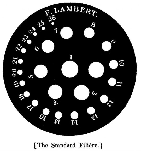
[ID: illustration of a black disc with gradated holes arranged in a spiral formation beginning with 1, largest, in the centre, and going to 26, smallest, at the edge. F. Lambert is written on the disc at the top. the illustration is labelled "The Standard Filière." end ID]
The sizing of Lambert's gauge was different from that of most SWGs and from any knitting pin gauges that would be made thereafter.
Seemingly in response to this, Elizabeth Jackson changed the frontispiece of the 1845 edition of The Practical Companion to the Work Table (London: Simpkin, Marshall, and Co.) to an illustration of a SWG. She writes (p. 14):
Some writers on the subject of Berlin wool work, have asserted that no standard measure exists; whilst others with equal truth but less modesty, have claimed the invention as their own. The writer of this volume begs to state that the above Gauge has been in use for centuries, and may be relied on for its perfect accuracy. It is the standard by which all wire manufacturers regulate their sizes, and may be obtained at the Berlin Brooms, York, or at any respectable ironmonger’s warehouse.
As Sheila Williams says, "[o]ne doesn't have to search far for the recipient of this barb!" (The History of Knitting Pin Gauges, p. 12). Lambert responds in the 5th edition of The Handbook of Needlework (London: John Murray, 1846) that the instrument "used by wire drawers for testing the diameters of their wires" was "a bulky and rude machine, little fitted for the work-table of a gentlewoman," and that smaller versions of these machines (probably referring to the little circular kind pictured above) tended to "vary" in their measurements and so produce problems in knitting (p. x).
It's worth noting that knitting for leisure was at this time the sole province of gentlewomen; other women also knitted to make useful items for their families or to produce items to sell, but most of the knitting guides being produced at this time were solidly marketed at and priced for gentlewomen, who were for one thing literate, and for another thing more likely to want to produce the "fancy work" (rather than "plain work") designs the books included. So if there is squeamishness here surrounding buying and using manufacturers' tools, that's important context for it.
Other writers of knitting guides came out with knitting gauges that would enable the buyer to produce any of the patterns in their book, error-free (they also claimed to be selling a gauge that conformed to the real standard and would thus be able to eliminate all of the buyer's confusion on the subject once and for all). Cornelia Mee produced one such gauge in 1842; Mrs. Savage in 1846; Mrs. Hope in 1848 (Williams pp. 14-16). These could be purchased by writing in to an address specified in the seller's knitting manual, or by visiting the storefront of the writer (if they had one). They were offered in various qualities of metal (from brass to silver-plate) and in various shapes.
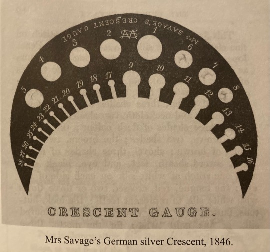
[ID: an illustration of a crescent-shaped gauge with holes in the centre of the shape and on the periphery of the inside part of the curve. holes are labelled from 1 (largest) to 28 (smallest). "Mrs. Savage's Crescent Gague" is inscribed on the gauge at the top, and the illustration is labelled "Crescent Gauge." the description of the illustration in Williams' book reads "Mrs. Savage's German silver Crescent, 1846". end ID]
The real revolution, however, came when George Chambers, a needle manufacturer (and thus more able to actually influence standards than the author of a knitting manual) produced the first "bell gauge" in 1847:
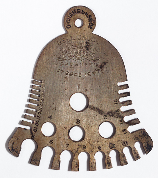
[ID: a flat piece of metal shaped like a bell. a circle with a hole in it is the "handle" at the top of the bell; "Chambers & Co." is inscribed on this part of the gauge. on the main body of the bell, "Bell Gauge Patented 17 Sept. 1847" is written and a coat of arms is engraved. the centre of the bell has holes from 1 (largest) to 4; the two sides and bottom of the bell have holes or slits from sizes 5 to 28. end ID]
These gauges were attractive because they were sturdy and cheap to produce (the shape can be punched out of a sheet of metal with little waste by making every other bell 'upside down'). In fact, the moment that it was legal to do so (after the failure of Chambers' business in 1858), other manufacturers started producing these bells without referencing Chambers' patent. This shape dominated knitting gauge production well into the 1930s.
Bell gauges were produced by manufacturers and stamped with that manufacturer's name and logo; they were also produced by manufacturers and then stamped with the name and logo of a small haberdashery or needle store for sale locally, so careful comparison of gauges is often necessary to find out which die they were cut from (and thus, which manufacturer they were made by). Gauges also continued to be made of ivory, bone, wood, vegetable ivory, and cardstock, in many different shapes and sizes. Sellers of knitting manuals continued to make them, as did some small local manufacturers; travelling peddlars would also sell them (Williams p. 21).
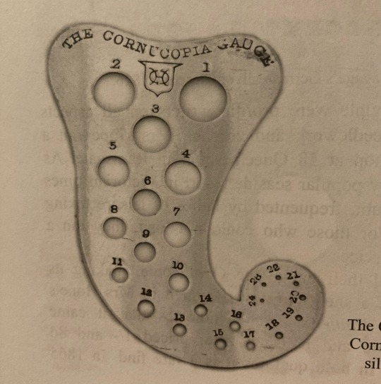
Mrs. Hope's cornucopia-shaped gauge, silver plate. 1848.

Mrs. Hope's cheaper version of a knitting gauge, 1865. [ID: an illustration of a rounded rectangular gauge with two lines of gradated slots running from 1 (largest) to 20 (smallest). Text on the page reads "The above is an engraving of a new instrument for measuring knitting pins and netting meshes. It is cheaper, more elegant, and offers greater facility in use than any similar articule, and is a correct measure for twenty sizes according to the numbers in this little volume, and in the works of Mrs. Gaugain, Mrs. Mee, and Miss Watts. Price in German silver, Five Shillings. Sold by all Berlin Shops, or post free of the Publisher for the amount in penny stamps." The page is labelled in Williams' book "Illustration from the 1865 edition of Hope's Knitter's Friend. end ID]
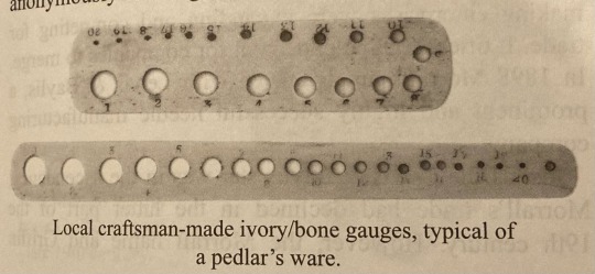
[ID: two rounded rectangular gauges, one longer and thinner than the other and the other having two lines of holes. they are labelled by Williams "Local craftsman-made ivory/bone gauges, typical of a pedlar's ware." end ID]
Knitting gauges would only become more in-demand in the 1870s, after the Education Act increased literacy. More and more knitting manuals would be produced for the common woman (Workwoman's Guide in 1838 had been an early exception), and bell gauges were cheap, durable, and mass-manufactured (Williams p. 22), with Henry Walker's "Archer" gauge being perhaps the most widely referenced and most easily attainable by collectors to-day (this gauge used the "Archer" logo after Walker's death in 1876). Gauges in other shapes would also continue to be produced.
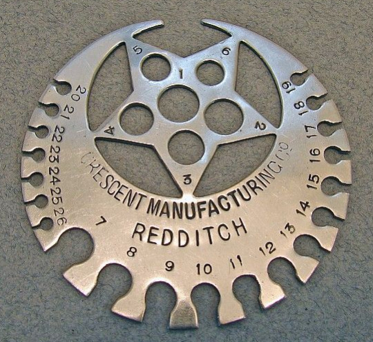
Crescent Manufacturing Co. star-and-crescent gauge, late Victorian.

Robert Hogg's club-shaped "Fairfax" knitting pin and wire gauge, 1896.
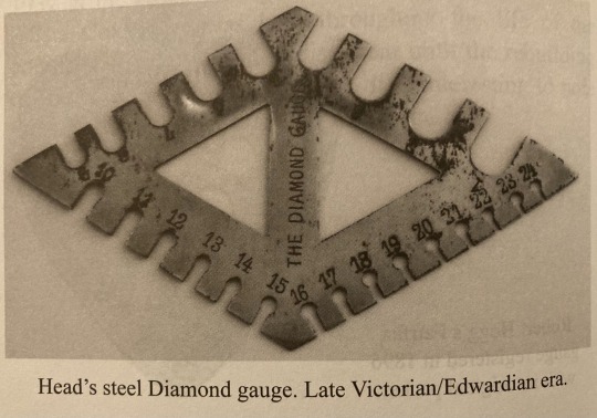
Head's steel Diamond gauge. Late Victorian/Edwardian era.
The history of these little knitting tools continues well into the 20th century, but the beginning of the 20th century is about where I start to lose interest. But these gadgets are very useful if you're trying to knit something from an antique pattern, as well as being very fun and downright cheap to collect. I now own several.
To learn more:
"Gauging the needs of knitters and crocheters." Loopholes, blog.
"Commend me to a knitting wife." Ragged Soldier, blog.
"The Bells." Wooly Thoughts & Mental Blocks, blog.
--"More Knitting Gauges."
The History of Knitting Pin Gauges, Sheila Williams. Out of print and hard to come by, but g*ogle books has a preview of it, or ask me to make a scan.
*Sheila Williams, in The History of Knitting Pin Gauges (p. 10), says 1842, but I don't think this is correct. Williams doesn't cite an edition or page number, but the 1842 first edition of Lambert's My Knitting Book (New York: Wiley & Putnam, pp. 93-4) illustrates a SWG and laments the lack of a standard, but does not introduce her filière.
#sorry to everyone who's been dutifully asking me about Victorian knitting gauges. as you can see this post took a while#knittng#knitblr#yarn crafts#yarnblr#questions#Victorian
26 notes
·
View notes
Text
How to Build Your Own 'Augmented Super Wife Supersoldier From The Future' Funko Pop.
A Semi-Coherent Guide By RC.
This is a long one. A loooooooong one.
I meant to do this like two and a half years ago, but in the spirit of keeping this fandom's head above water, and the fact I'm at the hospital (nothing serious!) with nothing to do for the next couple of hours, I'm doing it now.
So if, like me, you are still bitter that Grace and Dani didn't get official Funkos, or official *anything* due to manufacturer short-sightedness, why not say 'fuck it' and build yer own?
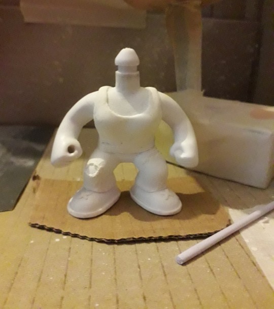
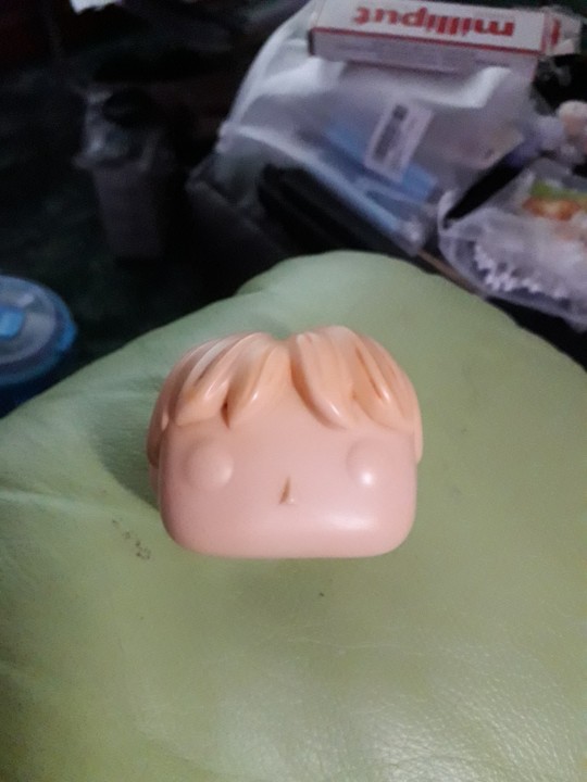
This rambling tutorial will attempt to demonstrate how to build Grace from the 'when they start to kill me, run' scene.
Like, literally that bit 😋.
Anywho. Let's do this!
You will need:
- Funko Pop DIY (female)
- Polymer clay (eg. Sculpy, Fimo, CosClay). I'd advise against cheapo no-name alternatives purely because in my experience the baking times/temperatures stated are absolute garbo. Also, polymer clay will give off quite gnarly fumes while curing, so better to use a trusted source. But if cheapo's all ya got, it's all ya got.
Other modeling materials you might consider instead of polymer clay include...
Epoxy clay (eg. Milliput, Apoxie Sculpt, The Army Painter 'Green Stuff', even something like J-B Weld or similar 2 part plumber's/repair putty).
Plain ol' air drying clay (eg. DAS, FimoAir, Gedeo).
You could even whip up a batch of 'cold porcelain', or an oven cure salt dough from ingredients you probably already have at home. Make sure you clear coat any salt dough creations properly after curing as over time ambient moisture may mess with it.
Each option above has its own pros and cons. Do your research if you aren't sure. Me? I used Fimo.
*ahem* Carrying on...
- Masking tape
- Hobby knife
- Pin vice
- Kebab skewer (wooden), or styrene rod
- Paint brushes
- Primer (plus dust mask if you're using a rattle can indoors)
- Sandpaper (around 400 grit oughta do it but you could probably go 200 either side of that and get a good result)
- Acrylic paints (optional: Posca PC-1MR pens in black and white for fine detail).
- Crafter's heat gun, or a hairdryer
- Varnish/clear coat.
Optional extras: Airbrush, spray booth/cardboard box, rotary tool, oven thermometer, artist's/cake decorating turntable, UV resin, silver leafing pen, jeweller's files, jeweller's wire, acetone, superglue or 5 minute epoxy, a lil piece of sponge, pearl mica powder, scavenged Funko Pop head 😈.
Step One: Grab your Funko DIY and separate the head from body using heat to soften the vinyl enough to wangle it off the neck post. Shoving it in a mug of hot water for a few minutes should do the trick. Make sure to dry out the head as much as possible. Last thing you want is mould growing inside it. This is Terminator, not The Last Of Us 😉. Alternatively you could use your heat gun/hairdryer, but I explain in Step Six why the water bath approach is a better option (imho) at this early stage.
(You are giving this entire thing a quick read through before you start, right? I dunno about the rest of you but I like to have at least a basic idea of the work ahead before I get stuck in. Saves finding out you're missing a necessary tool/material at an inopportune moment and all).
Stop rambling, RC. Sorry. It's easier to be succinct when you haven't lost half your photos 🤦♀️. Moving on...
If you don't wanna attempt to sculpt the hair yourself you can, as I did, take a kitbashing approach instead of using the supplied DIY head. Grab one of the many commercially available Funkos with a decent approximation of the hairstyle you want and then go Step One on em. Buy 'pre-loved', buy BNIB, dig one out of a dumpster, steal one from your lil cousin, it doesn't matter. Procure as your time/budget/situation dictates. Improvise where necessary.

Sorry, Ron. I need your floppy hair. I do not need your clothes.
Or your boots. Or your motorcycle.
...😋
Step Two: Take the body of the Funko DIY and mark out the position of the tank top and the cuffs of the jeans. These will be used as guides for when you add the clay.


At this point I used a pin vice to drill the hole thru the fist for the rebar. If you're a crazy person you could use a rotary tool with an appropriately sized bit attached.
To make the rebar I fashioned a mould from a drinking straw and filled it with UV resin. Because I'm awkward. A wooden kebab skewer, or some hobbyist's styrene rod (eg. Evergreen Scale Models) would work just as well. Just cut it to size, paint it silver and you're golden. I used a metallic leafing pen. You use whatever you've got handy. Doesn't have to be shiny. A flat grey acrylic would work just fine.
Use jeweller's files and sandpaper to make small adjustments to the hand hole and rebar respectively in order to get a good press fit. There's always glue if you overdo it 😉. But don't add the rebar to the model just yet, as you're gonna need room to manoeuvre for the next bit.
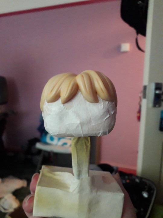
Step Three: How do you make it look like your figure is wearing clothes when you don't have much real estate to work with?
You fake it, that's how.
You do not need to model an entire set of clothes! It's an arse ache, and we're all about working smarter not harder on the RC channel.
So, take your modeling compound of choice, roll a chunk of it out to the desired thickness, and then cut into strips, say 2-3mm wide. Use your best judgement here.
Now, using the jeans as our example, wrap a strip around the bottom of the leg where the cuff would sit. Cut off any excess and blend out the join. Just give it a lil rub and it's like it was never there. Like magic! You should have a nice defined edge at the bottom, just above the foot. Now see the top edge of your lil clay strip? Well, you wanna start pushing and flattening the clay to blend the edge right out so it fades back into the body.
Repeat for the other leg, and the bottom of the tank top. The straps are relatively simple, tho the bits that pass under the arms can be fiddly due to lack of space. Use a hobby knife to shape and crisp up those edges and then blend out the extraneous edge. Same thing with the neckline.
Run a strip around each foot to form the soles of the boots, and a lil 'x' on the top of the feet to give the impression of laces.
For the rips in the clothing you can simply gouge out a little of the clay. If there isn't any on that part of the model (the knee for example) roll out a little wormy dealie (for you North of the Border fans 😉), position it as needed, blend out the edges, then gouge as required.
If you're playing on hardcore mode, this might be the time to start piling clay on the Funko DIY head and sculpting the hair. You may prefer to leave it til the head's re-attached tho. It depends on the material you're using. If you don't think it'll stand up to a bit of manhandling while pushing the head back onto the body, save this step til that bit's done.
Cure according to the clay manufacturer's instructions. The vinyl will not melt at the temperatures required to cure polymer clay, but if you don't wanna risk it or you don't wanna use your food oven to cook plastic, with all the gnarly fumes and stuff, I've given you plenty of air dry and/or non toxic alternatives. Consistent temperature is key with polymer clay. Undercooked, it's quite brittle. An oven thermometer comes in handy here if you've got one.
Step Four: Primetime!!! Some like to brush on primer, which is fine if you're painting a fence or throwing gesso on a canvas. Not so fine if you're painting a figurine imho. I mean, unless it's Cassandra from Doctor Who. A good rattle can of spray paint is what you want ideally, but again, it's about what you can afford/wangle/manage with your crafting space, so feel free to ignore me and brush away!
First rule of Primer Club: several light coats are better than one heavy coat. Second rule of Primer Club: knock each coat back a lil with sandpaper before applying the next one. Third rule of Primer Club: sit your rattle can in a warm water bath for five minutes before shaking it up to improve flow.
You can get primer specifically for plastics but while I would recommend it, it's not absolutely necessary.
A scavenged head may need masking off if the base colour already matches the skin colour of your character. Save yourself a bit of painting innit. You can get really tight, clean edges against the hairline with a hobby knife. If the hairstyle, hair colour, and skin colour match straight outta the box? Congrats! Why are you even reading this? 😜.
That thing in the background is a portable spray booth (that other thing is a turntable). A cardboard box is also a portable spray booth if you want it to be. Only thing it doesn't have is an extractor fan. So put on a dust mask, and open a window or work outside.
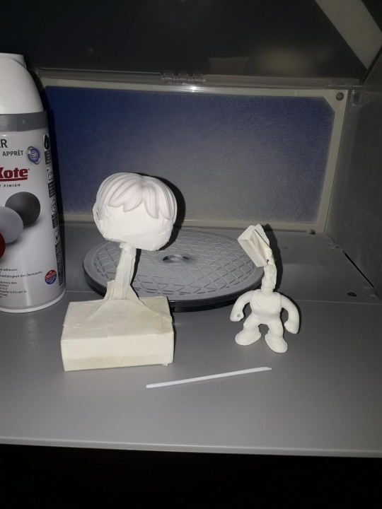
The DIY figure comes primed outta the box, so if you're using the DIY head and are planning on sculpting the hair after re-attachment you don't need to prime it. Unless you want to.
Step Five: Time to paint that shizz. You don't need me to walk you thru this bit, right?
Right?...
Masking is your friend if you don't trust your ability to freehand with a brush. If you're masking over a part you've already painted and are afraid of pulling the paint off, you can knock the level of tack on the tape down by sticking it to yourself (or your clothes) a couple of times before applying it. Some prefer to add a light layer of clear coat to 'lock in' the underlying paint. It's like a real life 'save point'. Some people do both. Some use masking fluid. Some use silly putty/blu-tac/plasticine. Play around, see what works. You do you.
I painted Grace's eyes blue coz Grace is extra and so am I. I threw a lil bit of pearl powder in there to add a subtle shimmer, as I thought going full metallic blue might be a bit too extra.
Lady Funkos have eyelashes. Don't forget the eyelashes.
(I nearly forgot the eyelashes).
A fine tipped Posca pen comes in handy here if you've got one.
Ditto the eyebrows, tho those aren't just for the ladies obvs.
For Grace's augmentation scars, again I recommend a Posca pen but a brush will do.
DO NOT PAINT THE NECK POST. Don't even varnish the neck post. Keep that bitch masked up until you're ready to reattach the head. Like, you can get away with painting the very bottom if you're worried the bare plastic will show even with the head attached, but that's it. Any more will be making a rod for your own back.
You have a choice now. Whether to weather your figure. I chose to add that extra level of detail as it made sense to me. Use a combination of dark washes, dry brushing, and/or sponge stipling to add dirt, blood etc. If ya want.
When you're happy with your paint job, give everything (except the neck post!!!!) a couple of layers of clear coat.
Step Six: When it comes to reattaching the head you probably don't wanna be dunking anything in water by this point, just in case. So we're gonna soften the neck post (and around the base of the head if necessary) with hot air instead. Use a hairdryer if you don't have a heat gun. DO NOT use an industrial or decorator's heat gun for the love o' god. That shit's meant for stripping paint, not gently warming vinyl figurines. It'd be like using a nuke to shake a cherry tree, and you'd likely burn yourself. A hairdryer is more than capable of doing the job.
Why did we not use the hairdryer for Step One? To be honest there's nothing stopping you if that's what you wanna do, but as you don't have direct access to the bits that need softening at that point you will have to wait for the heat to penetrate. You could be doing other things in that time by letting a water bath do the work for you.
Now, however, you do have direct access, so you'll probably find you only need to blast the hot air for 10 seconds or so.
Step Seven: So, you've got the head re-attached, and your paint job is finished and clear coated. That means it's time to add the rebar. If you went a bit too far with the drilling or sanding now's the time to get your glue on. As an final extra touch you can spiral some thin jeweller's wire around the length of the rebar to make it look more rebar-y. I didn't do this bit as the wire I had in my possession at the time was too thick for my tastes.
But whether you opt for that or not, congratulations on making your very own Grace Funko Pop!


I'm still planning on making security guard and future war versions of Grace, and at least one version of Dani. Yeah, I've been saying that for the last two years, but it's still absolutely happening, trust me.
Anyway. That'll do it. If you have any questions, or you need further explanations or recommendations etc. y'all know where to find me.
8 notes
·
View notes
Text
The Top 10 Jobs in Canada for 2024
Canada, with its picturesque landscapes, diverse culture, and robust economy, continues to attract individuals from around the world seeking new opportunities and a higher quality of life. As we step into 2024, the Canadian job market is brimming with exciting prospects across various industries. Whether you're a recent graduate, a seasoned professional, or an immigrant looking to build a career in the Great White North, here are the top 10 jobs in Canada that should be on your radar.
Software Developer: With the technology sector experiencing exponential growth, software developers are in high demand. From cutting-edge startups to established corporations, Canada's tech industry offers a plethora of opportunities for those with coding expertise.
Healthcare Professionals: The healthcare sector in Canada is perennially in need of skilled professionals, including nurses, doctors, and allied health workers. The aging population has led to a surge in demand for healthcare services, making it an excellent field for those looking to make a meaningful impact.
Construction Project Manager: As infrastructure projects continue to dot the Canadian landscape, the demand for construction project managers is on the rise. This role involves overseeing the planning, execution, and completion of construction projects, making it a key player in the nation's development.
Data Scientist: In an era driven by data, the role of a data scientist is crucial across various industries, including finance, healthcare, and e-commerce. Analyzing and interpreting large datasets, data scientists contribute valuable insights to guide decision-making processes.
Electrician: Skilled trades, such as electricians, are essential for maintaining and expanding Canada's infrastructure. From residential wiring to large-scale industrial projects, electricians play a pivotal role in ensuring the smooth functioning of the country's electrical systems.
Marketing Specialist: As businesses vie for consumer attention, the demand for marketing specialists continues to soar. Whether it's digital marketing, content creation, or market research, individuals with a flair for promoting products and services are sought after in the Canadian job market.
Registered Nurse: With an aging population, there's a growing need for compassionate and qualified nurses. Registered nurses are integral to the healthcare system, providing essential care and support to patients in hospitals, clinics, and long-term care facilities.
Mechanical Engineer: From designing innovative machinery to optimizing existing systems, mechanical engineers contribute significantly to Canada's industrial landscape. Industries such as manufacturing, automotive, and aerospace rely on the expertise of mechanical engineers to drive innovation.
Financial Advisor: Canadians are increasingly recognizing the importance of financial planning, leading to a surge in demand for financial advisors. Helping individuals and businesses make informed decisions about their finances, financial advisors play a crucial role in ensuring financial well-being.
Environmental Scientist: With a growing emphasis on sustainability, environmental scientists are in demand to address ecological challenges. From assessing environmental impact to developing conservation strategies, these professionals contribute to Canada's commitment to a greener future.
Conclusion:
As Canada continues to thrive on its commitment to diversity, innovation, and progress, the job market reflects these values with a wide array of opportunities. Whether you're drawn to the tech hub of Toronto, the vibrant culture of Vancouver, or the economic powerhouse of Calgary, these top 10 jobs offer a glimpse into the diverse career landscape that Canada has to offer. So, whether you're a local job seeker or an international talent looking to make Canada your home, these professions could be your stepping stones to a fulfilling and prosperous future.
2 notes
·
View notes
Last Seen Blogs

okkr-estrees
Kraftböck shipper from Russia

universal-casey
Your Local Idiot Shark

shima-draws
only in the darkness can you see the stars

mickeylaaa
Mikeyla 🌙
okkr-estrees
Kraftböck shipper from Russia