#ILI9341
Explore tagged Tumblr posts
Visit Tumblr Blog
Explore Tumblr blogs with no restrictions, modern design and the best experience.
Last Seen Tumblr Blogs


Fun Fact
The total number of visits Tumblr.com received during January 2021 is 327 million.
Text
DIY: Marauder with Screen and GPS For Flipper Zero
Many of you would have seen the humongous ESP32 add-on module with touch screen and GPS for Flipper Zero shared in discussion groups, forums, etc. Well, this tutorial will provide you with all the information you need to build one yourself.
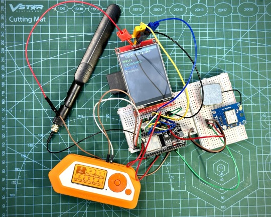
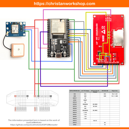
This build consists of mainly 4 parts. The TFT LCD 2.8" 240x320 SPI ILI9341 Touch Display cost me around US$5.50, the ESP32-WROOM-32U module cost around US$3, the NEO-6M GPS module cost around US$2.20 and an 8dbi 2.4GHz Wifi Antenna which cost around US$2. All of these parts can be easily found in online marketplaces like Aliexpress, Amazon, etc. Here is how you need to wire them up together. How you wish to lay this out or mount on a prototyping board is entirely up to you. As long as the connections are correct, you are good to go. The GPS module is optional, and mainly, it's used for the war driving functionality.
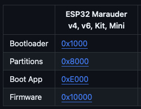
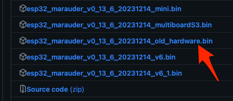
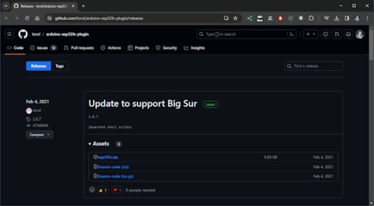
Next, you need to download all the firmware needed from here. Please download the Bootloader, Partitions, Boot App and Firmware files for v4 (Yes, v4 files, not any others) and save it on your computer.
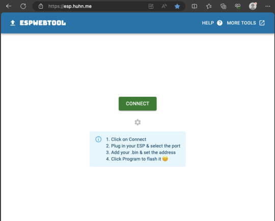
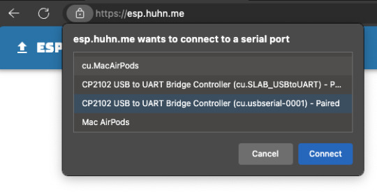
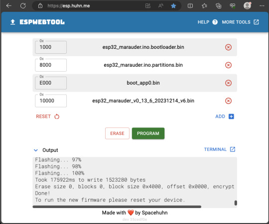
Now, press and hold the BOOT button on your ESP32-WROOM-32U module and connect it to your computer using a data-capable USB cable (some USB cables can only charge), then let go the BOOT button. Open Google Chrome or Microsoft Edge browser and go to ESPWebTool. Click the CONNECT button, then select the ESP32 usb serial connection. It should look something like below but can vary a little between different computers and operating systems.
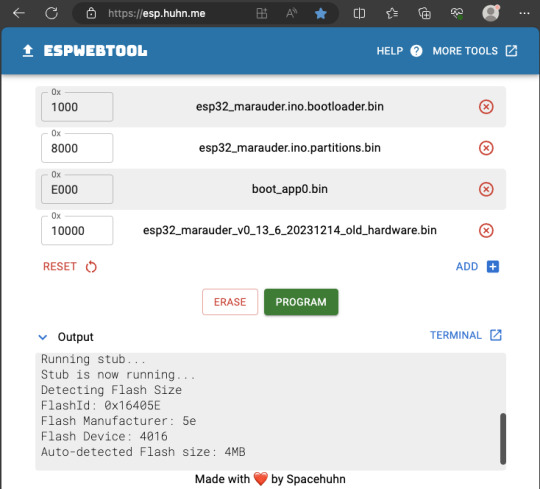
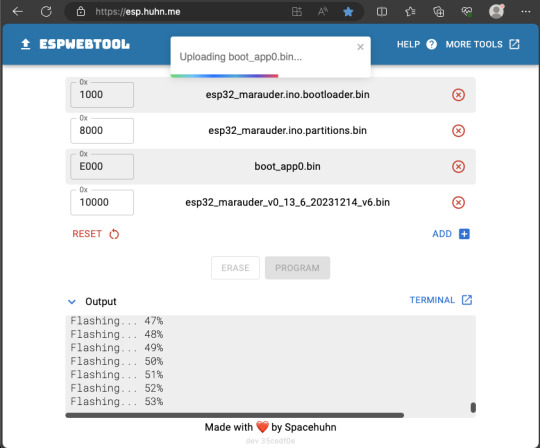
Select the firmware files for each slot exactly like below (take note of the 0x1000, 0x8000, etc. and their corresponding .bin files), then hit the PROGRAM button.
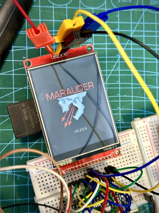
When completed successfully, you can unplug the USB cable from the ESP32 module and now you can connect your Marauder module to your Flipper Zero. Please ensure that your Flipper Zero is turned off before you connect it, and also turn off your Flipper Zero before disconnecting it. The 3.3V pin is also used by your Flipper Zero's SD card reader and connecting/disconnecting external modules that use this pin while the Flipper Zero is on can potentially corrupt the SD card. So, if everything went according to plan, your Marauder module should boot up and everything should look like below.
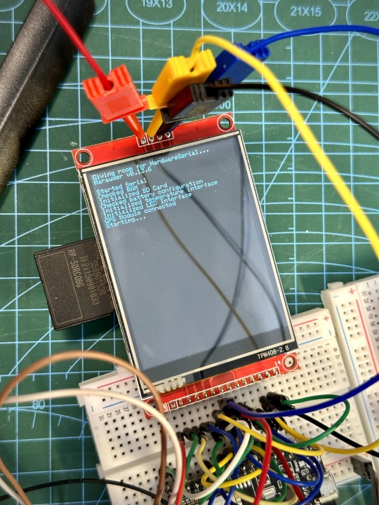
NOTE: If your Marauder boots up, but when you try to touch the screen and get no response, try tapping around the bottom part of your screen and see if the touch panel seems to be in inverted position from the actual display. Should this happen to you, just flash your ESP32 module again following the steps above, but use the v6 firmware. This should resolve the issue.
In this build, I just prototyped this on breadboard, but you can of course make it permanent by soldering it on to a prototype board and 3D print a case for it. This setup is essentially just using the Flipper Zero as a battery pack, instead of using the Flipper Zero to control Marauder. The large screen does make some things easier to do, compared to the small screen of the Flipper Zero, and there may be some functionality (not much) that is not currently in the Flipper Zero Marauder companion app. Here is a video showing the different menus in Marauder.
Personally, I don't think I will actually want to bring something so big around with me, along with my Flipper Zero. I think what makes Flipper Zero special is just how compact it is and all the different functionality cramped into it. This would probably be better off as a standalone unit by just hooking up a battery, but that's just me. Well, that's it for this tutorial. I hope you found this helpful.
Here's a good intro to Marauder if you are unfamiliar.
youtube
18 notes
·
View notes
Text
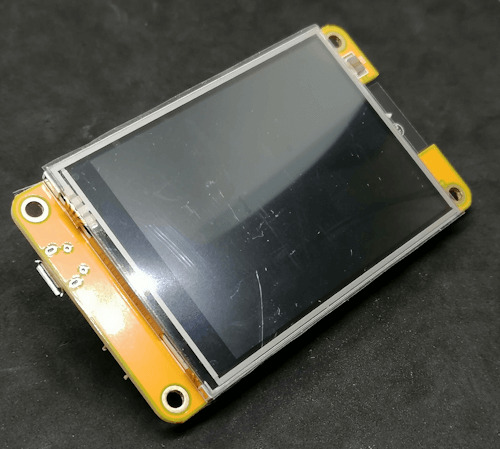
ESP32 Development Board mit 2,8 Zoll Touch Display: Programmieren für Anfänger
In diesem Beitrag möchte ich dir ein ESP32 Development Board mit Touch Display vorstellen und zeigen wie dieser programmiert wird. https://youtu.be/xEy-4FJiRHs Ein herzliches Dankeschön an lowstreaming für die großzügige Unterstützung mit dem ESP32 Mikrocontroller. Diese Geste ermöglicht mir, die spannenden Möglichkeiten des Mikrocontrollers und des 2,8 Zoll (ca. 7 cm) Touch Displays zu erkunden und gemeinsam Lösungen zu finden. Deine Unterstützung macht diese technologische Reise besonders inspirierend. Vielen Dank!

Bezug
Diesen Mikrocontroller bekommst du auf ebay.de für derzeit knapp 18 €* inkl. Versandkosten. Auf alieexpress.com findest du dieses Modul unter "ESP32 Development Board 2.8inch LCD TFT" jedoch deutlich günstiger, jedoch musst du dort mit einer längeren Lieferzeit rechnen. Hinweis von mir: Die mit einem Sternchen (*) markierten Links sind Affiliate-Links. Wenn du über diese Links einkaufst, erhalte ich eine kleine Provision, die dazu beiträgt, diesen Blog zu unterstützen. Der Preis für dich bleibt dabei unverändert. Vielen Dank für deine Unterstützung!
Lieferumfang
Zum Lieferumfang gehört neben dem Mikrocontroller noch: - ein Micro-USB-Kabel, - ein Stift für den Touch Screen, - ein Anschlusskabel

Pinout des ESP32 Development Board 2.8inch LCD TFT
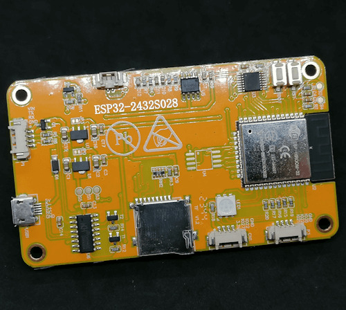
Schauen wir uns zunächst den Aufbau des ESP32 Development Boards an. Auf der Vorderseite findest du das 2,8 Zoll TFT Touch Display. Auf der Rückseite wird es schon spannender, denn dort findest du einige Schnittstellen.
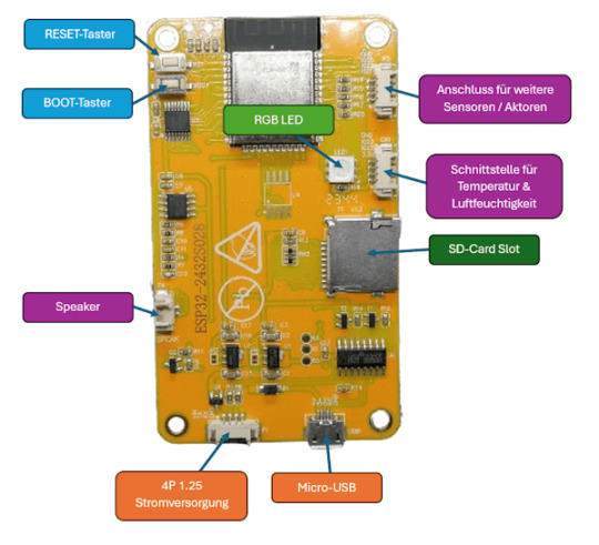
Aufbau ESP32 Development Board mit 2,8 Zoll TFT Touch Display An den beiden seitlichen Schnittstellen kannst du zusätzliche Sensoren / Aktoren anschließen und programmieren. Des Weiteren findest du noch eine RGB LED, an welcher du die Farben separat via PWM Signal steuern kannst (es ist also keine WS18B20 LED oder ähnliches).
Beschriftung der Schnittstellen und RGB LED am ESP32 Development Board
Technische Daten des ESP32 Development Board mit 2,8 Zoll Touch Display
ModellESP32-2432S028RProzessorESP32-WROOM-32(ESP32-D0WDQ6) Espressif ESP32 32 Bit Dual Core ProzessorBildschirmTFT Display mit ILI9341 Treiber, Auflösung: 240 px x 320 px, 2,8 Zoll (ca. 7 cm) TFT-Display, TouchscreenBetriebstemperatur -20 bis + 70 °CVersorgungsspannung5V, ca. 90 mAGewicht44 gModulgröße8,6 cm x 5,4 cm
Anschluss an den Computer und installieren des CH340 Treibers
Wenn du diesen Mikrocontroller an deinen Computer mit dem mitgelieferten Micro-USB-Kabel anschließt, dann sollte dieser sofort erkannt werden.
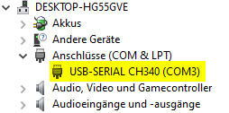
Wenn dieser nicht erkannt wird, wie in der Grafik zu sehen, dann musst du den Treiber für den USB-Serial Converter CH340 installieren. Diesen Treiber kannst du dir unter https://www.wch.cn/download/CH341SER_ZIP.html herunterladen. Die Webseite ist leider auf Chinesisch, aber du kannst dir diese recht einfach im Browser mit wenigen Klicks übersetzen lassen.
Programmieren des ESP32 Development Board in der Arduino IDE
Zunächst möchte ich dieses Board in der Arduino IDE programmieren. Sämtlichen Quellcode von den Beispielen findest du auch auf meinem GitHub Repository unter StefanDraeger/ESP32_Development_Board_ESP32-2432S028R. Installieren des Boardtreibers für den ESP32 Dazu muss zunächst der Boardtreiber für den Mikrochip ESP-WROOM-32 installiert werden. Im ersten Schritt müssen wir wie erwähnt den Boardtreiber installieren, dazu navigieren wir zu den Einstellungen und wählen dort die Schaltfläche hinter "Zusätzliche Boardverwalter URLs"(1).

Im neuen Dialog geben wir nun die nachfolgende Adresse(2) ein. https://raw.githubusercontent.com/espressif/arduino-esp32/gh-pages/package_esp32_index.json Und bestätigen dieses mit der Schaltfläche OK (3).

Jetzt können wir zum Boardverwalter (4) wechseln und nach ESP32(5) suchen. Aus der Ergebnisliste wählen wir im Eintrag "esp32 von Espressif Systems" (6) die Schaltfläche INSTALLIEREN. In meinem Falle ist diese bereits in der derzeit aktuellen Version 2.014 installiert und ich habe hier die Schaltfläche ENTFERNEN (7).

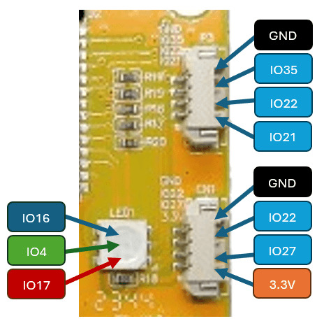
Programmieren der RGB LED Auf der Rückseite des ESP32 Development Boards findest du eine RGB LED, welche du über die nachfolgenden Pins via PWM Signal steuern kannst. - Rot > IO17 - Grün > IO4 - Blau > IO16 Beispiel - setzen einer Farbe an der RGB LED via PWM Signal Auf der Seite https://www.rapidtables.com/web/color/RGB_Color.html findest du einen einfachen ColorPicker aus welchem du dir eine Farbe auswählen und den RGB Wert ablesen kannst.
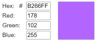
Diesen RGB Wert (R = red, G = green, B = blue) setzt sich aus den Farben rot, grün und blau zusammen. Diese Farbe kannst du dann mit der Funktion "analogWrite(, )" setzen. //RGB LED //LED, Farbe rot #define ledRed 17 //LED, Farbe grün #define ledGreen 4 //LED, Farbe blau #define ledBlue 16 void setup() { //definieren das die Pins als Ausgang dienen pinMode(ledRed, OUTPUT); pinMode(ledGreen, OUTPUT); pinMode(ledBlue, OUTPUT); //setzen der Farbe lila an der RGB LED //Farbe rot mit 178 von max. 255 analogWrite(ledRed, 178); //Farbe grün mit 102 von max. 255 analogWrite(ledGreen, 102); //Farbe blau mit dem maximalen Wert von 255 analogWrite(ledBlue, 255); } void loop() { } Wenn der Quellcode nun übertragen wurde, dann sollte die RGB LED in der Farbe Lila aufleuchten.
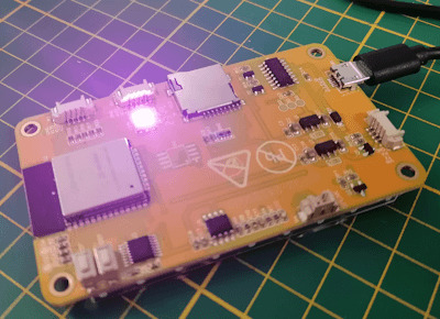
Programm - setzen der Farbe Lila an der RGB LED des ESP32 Development BoardHerunterladen Beispiel - anzeigen aller Farbkombinationen an der RGB LED Wir können jetzt mit drei For-Schleifen alle Farbkombinationen auf der RGB LED aufleuchten lassen. Dazu müssen wir lediglich in jeder Schleife den entsprechenden Farbwert setzen. //RGB LED //LED, Farbe rot #define ledRed 17 //LED, Farbe grün #define ledGreen 4 //LED, Farbe blau #define ledBlue 16 void setup() { //definieren das die Pins als Ausgang dienen pinMode(ledRed, OUTPUT); pinMode(ledGreen, OUTPUT); pinMode(ledBlue, OUTPUT); } void loop() { //For-Schleifen über die einzelnen Farbwerte for (int red = 0; red < 255; red++) { //setzen der Farbe rot mit dem aktuellen Wert aus der For-Schleife analogWrite(ledRed, red); for (int green = 0; green < 255; green++) { //setzen der Farbe grün mit dem aktuellen Wert aus der For-Schleife analogWrite(ledGreen, green); for (int blue = 0; blue < 255; blue++) { //setzen der Farbe blau mit dem aktuellen Wert aus der For-Schleife analogWrite(ledBlue, blue); //eine kleine Pause von 25 Millisekunden delay(25); } } } } TFT-Touchdisplay programmieren Als Nächstes möchte ich dir gerne zeigen, wie das TFT-Touchdisplay programmiert wird. Installieren der benötigten Bibliothek zum Ansteuern des TFT-Touchdisplays Bevor wir Text, Bilder oder geometrische Formen auf dem TFT-Display anzeigen können, müssen wir eine Bibliothek installieren. In der Arduino IDE öffnen wir dazu den Bibliotheksverwalter (1) und suchen dort nach "TFT_eSPI" (2), um diese Bibliothek jetzt zu installieren, müssen wir auf die Schaltfläche "INSTALLIEREN" klicken. In meinem Fall habe ich diese Bereits installiert und bei mir wird die Schaltfläche "ENTFERNEN" angezeigt.

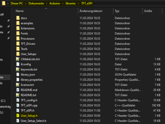
Diese Bibliothek kommt mit sehr vielen Beispielen daher, welche wir jedoch erst nach einer kleinen Änderung i lauffähig auf den Mikrocontroller aufspielen können. Konfiguration für das TFT-Display setzen Bevor wir jedoch mit dem TFT-Display arbeiten können, müssen wir die Konfiguration setzen, diese geben wir in der Datei "User_Setup.h" ein. Die Datei findest du im Ordner C:Users%username%DocumentsArduinolibrariesTFT_eSPI Es ist ratsam sich von der originalen Datei eine kopie zu erstellen so das man ggf. noch andere Displays später programmieren kann.
Die nachfolgende Konfiguration habe ich vom GitHub Repository https://github.com/OttoMeister/ARDUINO_ESP32-2432S028R entnommen und funktioniert für den hier gezeigten Mikrocontroller. #define ILI9341_2_DRIVER #define TFT_WIDTH 240 #define TFT_HEIGHT 320 #define TFT_BL 21 #define TFT_BACKLIGHT_ON HIGH #define TFT_MOSI 13 #define TFT_SCLK 14 #define TFT_CS 15 #define TFT_DC 2 #define TFT_RST 12 #define TFT_BL 21 #define TOUCH_CS 33 #define LOAD_GLCD #define LOAD_FONT2 #define LOAD_FONT4 #define LOAD_FONT6 #define LOAD_FONT7 #define LOAD_FONT8 #define LOAD_GFXFF #define SMOOTH_FONT #define SPI_FREQUENCY 55000000 #define SPI_READ_FREQUENCY 20000000 //Touch Screen: ?????????ß #define XPT2046_IRQ 36 #define XPT2046_MOSI 32 #define XPT2046_MISO 39 #define XPT2046_CLK 25 #define XPT2046_CS 33 #define SPI_TOUCH_FREQUENCY 2500000 Beispiel - Text "Hallo Welt!" auf dem TFT-Display anzeigen Schreiben wir zunächst auf das TFT-Display den Text "Hallo Welt!" in unterschiedlicher Textgröße, Farbe und Position. //Bibliothek zum ansteuern des TFT Displays #include #include //Datei mit den definierten Schriftarten #include "Free_Fonts.h" //eine instanz vom TFT Display Objekt erstellen TFT_eSPI tft = TFT_eSPI(); void setup(void) { //beginn der kommunikation mit dem TFT Display tft.init(); //drehen des Displays tft.setRotation(3); //Hintergrundfarbe auf Schwarz setzen tft.fillScreen(TFT_BLACK); //Textfarbe Magenta mit Hintergrundfarbe Schwarz tft.setTextColor(TFT_MAGENTA, TFT_BLACK); //Schriftart FSB9 setzen tft.setFreeFont(FSB9); //den Cursor an die Position x=10 & y=45 setzen tft.setCursor(10, 45); //den Text "Hallo Welt!" an die gesetzte Cursorposition //schreiben tft.print("Hallo Welt!"); //Weitere Texte mit unterschiedlichen Farben, Positionen und //Schriftgrößen auf dem TFT-Display anzeigen tft.setTextColor(TFT_VIOLET, TFT_BLACK); tft.setFreeFont(FSB12); tft.setCursor(10, 65); tft.print("Hallo Welt!"); tft.setTextColor(TFT_PINK, TFT_BLACK); tft.setFreeFont(FSB18); tft.setCursor(10, 95); tft.print("Hallo Welt!"); tft.setTextColor(TFT_GREEN, TFT_BLACK); tft.setFreeFont(FSB24); tft.setCursor(10, 130); tft.print("Hallo Welt!"); } void loop() { } Der Code bewirkt nun das auf dem Display der Text "Hallo Welt!" in unterschiedlichen Textgrößen, Farben und Positionen angezeigt wird.

Programm - schreiben von Text auf dem TFT-Display des ESP32 Development BoardHerunterladen Beispiel - Bild auf dem TFT-Display anzeigen Zur Bibliothek TFT_eSPI erhältst du wie erwähnt sehr viele Beispiele, eines davon ist "LittleFS_PNG". Dieses Beispiel demonstriert wie du ein Bild auf dem Display anzeigen lassen kannst. Einrichten eines LittleFS Dateisystems auf dem ESP32 Das LittleFS ist ein eigenes kleines, leichtgewichtiges Dateisystem welches auf Embeddedsystems wie dem ESP32 anwendung findet. Die Dateien werden dabei auf dem ESP32 Chip gespeichert und nicht auf der SD-Karte! Damit du Daten auf den Chip in diesem speziellen Format speichern kannst, benötigst du ein Plugin als JAR-Datei, jedoch kann du dieses nur in die klassische Arduino IDE (Version 1.8.x) integrieren.
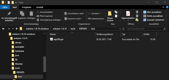
Ich habe mir nun die derzeitige Version 1.8.19 als ZIP-Datei heruntergeladen und entpackt. Im nächsten Schritt muss nun der Pfad wiefolgt angelegt werden arduino-1.8.19toolsESP32FStool und in diesen Ordner die Datei esp32fs.jar abgelegt werden.
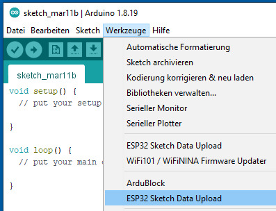
Ablegen von Dateien auf dem LittleFS Dateisystems In meinem Fall wechsel ich jetzt also nun von der neuen Arduino IDE 2.x zur klassischen Version um eine Datei auf den Mikrocontroller hochzuladen. Das Plugin findest du unter Werkzeuge > ESP32 Sketch Data Upload.
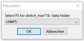
Wenn nun auf den Menüeintrag "ESP32 Sketch Data Upload" geklickt wird, öffnet sich ein Dialog in welchem wir das Dateisystem auswählen.
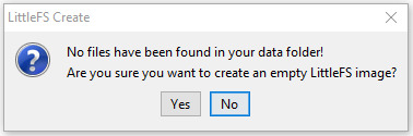
Im Ersten durchgang existiert der Ordner "data" im Sketch Ordner nicht und daher muss dieser zunächst angelegt werden. Daher bestätigen wir diesen Dialog mit der Schaltfläche "Yes". Wenn der Ordner und der Mikrocontroller vorbereitet wurden dann wird dir dieses in der Konsole mit dem Text "Hard resetting via RTC pin..." angezeigt.

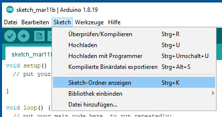
Wir können jetzt mit der Tastenkombination Strg + K oder über das Menü Sketch > Sketch-Ordner anzeigen in den Sketch Ordner wechsel und sollten nun einen zusätzlichen Ordner "data" sehen. Dieser Data liegt quasi paralell zur unserer INO-Datei. Read the full article
0 notes
Text

https://www.pishop.ca/product/2-8-tft-lcd-with-touchscreen-breakout-board-w-microsd-socket-ili9341/
0 notes
Video
instagram
#maker #ILI9341 #SaveOppy #wakeupoppy #arduino https://www.instagram.com/p/BoRh7cEF_Ru/?utm_source=ig_tumblr_share&igshid=7beg2nj88nh3
2 notes
·
View notes
Text
ESP32 ILI9341: display jpg image
ESP32 ILI9341: display jpg image
Introduction In this tutorial we will learn how to render a .jpg image on a ILI9341 display, using the ESP32 and the Arduino core. For a tutorial on how to wire the ESP32 to the ILI9341 display and render some text, please check here. The code shown in the sections below assumes the same wiring from the mentioned tutorial. If you are using a different wiring configuration, please make sure to…

View On WordPress
#Arduino#Arduino_GFX#display image#embedded system#ESP32#File System#ILI9341#jpg#programming#SPIFFS#TJpg_Decoder
0 notes
Text
出鼻を挫かれたか・・・
Spresenseでアプリケーション開発をしようと色々と調べています。昨日、ili9341コントローラーを搭載したAdafruitのTFT LCDをSpresenseに接続してサンプルを動かそうとしましたが、どうやってもうまく行きませんでした。
NXのウィンドウを描画するタイミングで一瞬表示がチラつくという症状でした。

夜になってArduino NanoやArduino Unoで試したら似たような症状でしたのでLCDが壊れているようです。一度も表示することのなかったLCDでした。
並行してデバッグ用のICEが欲しくて、LPC-Link2を購入。こちらはなんと付属のフラットケーブルが同梱されていませんでした。

Spresense側に10ピンのピンヘッダーをはんだ付けしないと使えないので、仮にケーブルがあっても使えませんが。
ピンヘッダーを買わないとね。
View On WordPress
0 notes
Photo

Configuring raspberry pi 3 LCD touch display #lcd #ili9341 #raspberrypi #raspberrypi3 #raspberrypi3b #installingdrivers #waveshare #rpi #retropie #itworks💚
#waveshare#raspberrypi3b#rpi#ili9341#raspberrypi#installingdrivers#lcd#raspberrypi3#retropie#itworks💚
0 notes
Text
ESP32 Display is Worth a Thousand Words
The ESP32 is the successor to the wildly popular ESP8266. There seems to be no end to what the chips can do. However, despite all the wireless communication capabilities, the module doesn’t have a display. [G6EJD] wanted to connect an ILI9341 TFT display and he put the code and information on GitHub. You can also see a video of his work, below. Since the display uses a serial interface, there isn’t much wiring required. The Adafruit GFX library does the heavy lifting, utilizing the SPI library for the actual communications. The first demo shown on the hardware can pull weather …read more http://pje.fyi/PS3pC1
0 notes
Text
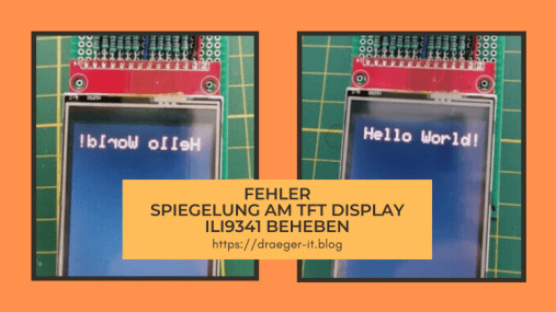
LCDWIKI Bibliothek - gespiegelte Ausgabe auf dem 2,4" TFT Touch Display (ILI9341)
Wenn du das Problem hast, dass du eine gespiegelte Ausgabe auf deinem 2,4" TFT Display (ILI9341) mit der Bibliothek LCDWIKI hast, dann habe ich hier die Lösung für dich.

In einem neuen Beitrag möchte ich ein 2,4" TFT Touch Display programmieren, dabei ist mir der Fehler aufgefallen, dass die Ausgabe auf dem Display spiegelverkehrt ist. Eine doch recht lange Google Suche brachte mich dann auf die Lösung, welche ich dir hier gerne auf Deutsch präsentieren möchte.

Fehler - gespiegelte Ausgabe auf ILI9341 mit LCDWIKI

Fehler behoben - gespiegelte Ausgabe auf ILI9341 mit LCDWIKI Die Lösung findest du auf den beiden nachfolgenden Seiten auf Englisch: - https://github.com/lcdwiki/LCDWIKI_kbv/issues/3 - https://forum.arduino.cc/t/mirror-display-on-lcdwiki-library-with-2-4-tft-lcd/678776 Jedoch behandeln diese eine ganz andere C++ Datei, daher wird man zunächst auf eine falsche Fährte gelockt. Jedoch gibt es diese C++ Datei in den LCDWIKI Bibliotheken nicht bzw. nicht mehr.
Lösung - LCDWIKI gespiegelte Ausgabe ILI9341
Die Lösung liegt in diesem Falle darin, die Datei "LCDWIKI_SPI.cpp" zu modifizieren. Du findest diese Datei in dem Ordner "C:UsersDocumentsArduinolibrariesLCDWIKI_SPI". Wenn du jedoch deine Arduino IDE woanders installiert hast, ist dieser Pfad nicht korrekt, den korrekten Pfad findest du in deinen Einstellungen. Dazu navigierst du über File (1) > Preferences... (2) zu dem Dialog Preferences. Aus diesem kannst du nun das Verzeichnis entnehmen, in welchem die Sketche & Bibliotheken gespeichert werden. Die Bibliotheken findest du wiederum im Unterverzeichnis libraries.

Arduino IDE - Einstellungen für die Ablage von Sketches & Bibliotheken modifizieren der Datei LCDWIKI_SPI.cpp Die Zeilen 1257 bis 1271 müssen ausgetauscht werden. switch (rotation) { case 0: val = ILI9341_MADCTL_MX | ILI9341_MADCTL_BGR; //0 degree break; case 1: val = ILI9341_MADCTL_MV | ILI9341_MADCTL_BGR; //90 degree break; case 2: val = ILI9341_MADCTL_MY | ILI9341_MADCTL_ML |ILI9341_MADCTL_BGR; //180 degree break; case 3: val = ILI9341_MADCTL_MX | ILI9341_MADCTL_MY| ILI9341_MADCTL_ML | ILI9341_MADCTL_MV | ILI9341_MADCTL_BGR; //270 degree break; } Gegen diesen Code: switch (rotation) { case 0: val = ILI9341_MADCTL_ML | ILI9341_MADCTL_BGR; //0 degree break; case 1: val = ILI9341_MADCTL_MY|ILI9341_MADCTL_MV | ILI9341_MADCTL_BGR; //90 degree break; case 2: val = ILI9341_MADCTL_MY|ILI9341_MADCTL_MX|ILI9341_MADCTL_MH|ILI9341_MADCTL_BGR; //180 degree break; case 3: val = ILI9341_MADCTL_MX | ILI9341_MADCTL_MV | ILI9341_MADCTL_BGR; //270 degree break; }
Download der korrigierten Bibliotheken
Wenn du die Datei nicht selber bearbeiten und austauschen möchtest, dann kannst du dir auch die Bibliotheken als gemeinsame ZIP-Datei herunterladen. Du musst nur die ZIP-Datei "LCDWIKI_ILI9341_libs.zip" auf deinem PC entpacken und die darin enthaltenen ZIP-Dateien über deine Arduino IDE importieren. Read the full article
1 note
·
View note
Text
BTC Ticker ESP32 Module for Arduino Source Bitcoin Price Ticker Program 4 MB SPI Flash
BTC Ticker ESP32 Module for Arduino Source Bitcoin Price Ticker Program 4 MB SPI Flash
Price: (as of – Details) Characteristics: Lastest ESP32 Version: REV1 WIFI Bluetooth 4 MB Flash 4 MB PSRAM TF Reader 3D ANTENNA 2A Battery Management LED indicator: There are 4 LEDs show the battery status in real time. Power button: Click one time will start. Fast click 2 times will shut down. ILI9341 2.2Inch TFCARD Protection: Short protection Over charging protection Overflowing Button…

View On WordPress
0 notes
Photo

#opensource #weekend #maker #ESP32 #Arduino #SaveOppy #opportunity #NASA #OppyPhoneHome #ILI9341 https://www.instagram.com/p/BoKAgU_nIvy/?utm_source=ig_tumblr_share&igshid=1mj08zpxil1ga
0 notes
Text
ESP32 ILI9341: Drawing shapes
ESP32 ILI9341: Drawing shapes
Introduction In this tutorial we will learn how to draw shapes on a ILI9341 display, using an ESP32, the Arduino core and the Arduino_GFX library. For an introductory tutorial on how to get started controlling a ILI9341 with an ESP32, please check here. The tutorial contains the wiring diagram between the ESP32 and the display, and how to write a simple “Hello World” message using the…

View On WordPress
0 notes
Text
CentSDRに使えるLCDパネルのバリエーション
CentSDRのLCDは、ILI9341というSPIで制御するコントローラを使用していますが、ILI9431を使用したパネルは複数のタイプが入手可能です。いくつか試してみました。

当初から使用していたのは、2.2’’と小型のパネルでした。小型ゆえにピクセルの密度が高く少し小さめでした。安価に入手可能なので標準的に使用しています。
CentSDRキットの製作レポートを拝見していると、2.8’’のパネルを使用したモジュールがそのまま使えているとの報告がありました。2.2’’は9ピン、2.8’’は14ピンとピン数は違うのですが、9ピン部分は同じ配列になっているので、そのまま使うことができるということでした。さっそく入手してみると、なかなか良さそうです。基板の縦サイズもほぼ一致していてちょうど良い感じです。

液晶モジュールは横にはみ出ます。

こんな感じでピンが余ります。無接続で問題はありません。

この液晶パネルは安価ながら、タッチパネルとコントローラチップが搭載されていて、上記の余ったピンからSPIで制御することができるようです。これを機能するようにするのも試してみたいと思いました。
もう一つ良いと思ったのが、ノイズレベルの低さです。AM放送の中波帯では液晶パネルを原因とするノイズが少し目立っていたのですが、この液晶ではそれが見当たらないのです。写真下が現在入手可能な2.2’’のタイプですが、無信号で最大ゲインの状態だと、こんな感じでゆらゆらとゆれるスイッチングノイズが見えています。右上の2.2’'は以前入手したものですが、こちらはノイズは見えません。品種が違うようで最近は入手できないようです。

それに対して、左上の2.8'’ではノイズが見当たりません。もしかすると他の周波数帯をよく探せば見つかるかもしれませんが、さっと見た限りでは見当たりません。というわけで、ノイズの点でも2.8’'タイプは現時点でオススメと思います。
続いてもう一つ、2.4’’の液晶を基板裏面に取り付けるバージョンです。今回頒布した2nd lot版の基板の裏面にはこんなパターンを用意してありました。

これは液晶パネルのフレキケーブルを接続するためのパターンです。NanoVNAで使用したのと同じ、2.4''タイプの基板無しパネルのみの液晶用です。まだ試していなかったのですが、今回ようやく取り付けてみました。

基板が無いタイプのモジュールですので、とても薄く仕上がります。10mm程度で納まります。

このパネルには抵抗膜タイプのタッチパネルが付いています。回路側には、このタッチパネルをADCで制御するための用意がしてあります。ですのでやろうと思えばタッチ操作を実装しようと思えば可能です。ただ、操作体系を変更するのは、それなりにソフトウェアの実装に気合が必要なので、実装は時間がかかりそうです。なので現在は操作はできず、USBからコマンドを送っての制御のみです。
タッチ操作を実装できればロータリエンコーダは不要になります。基板をカットできるようにレイアウトしてあります。うまくいけばカードサイズの薄型超小型受信機が作れると思っています。
というわけで、2.2’’, 2.4’’, 2.8’’と3種の液晶をCentSDRで試してみました。実際に動かしてみると、単にサイズだけではなく、いろいろと違いが見えてきます。今後の設計の参考にしたいと思います。
参考
Blade7さん CentSDR の組み立て (3) https://blade8873.blogspot.com/2018/07/centsdr-3.html
2 notes
·
View notes
Text
This Arduino Terminal Does All The Characters
The job of a dumb terminal was originally to be a continuation of that performed by a paper teletype, to send text from its keyboard and display any it receives on its screen. But as the demands of computer systems extended beyond what mere ASCII could offer, their capabilities were extended with extra characters and graphical extensions whose descendants we see in today’s Unicode character sets and thus even in all those emojis on your mobile phone. Thus a fully-featured terminal has a host of semigraphics characters from which surprisingly non-textual output can be created. It’s something [Michael Rule] has done some work on, with his ILI9341TTY, a USB serial terminal monitor using an Arduino Uno and an ILI9341 LCD module that supports as many of the extended characters as possible.
A graph, entirely in Unicode characters.
It’s fair to say that most of us who regularly use a terminal don’t go far beyond the ASCII, as it’s likely that a modern terminal will sit in a window over a desktop GUI. So even if you have little use for a hardware terminal monitor there’s still plenty of interest to be found in those rarely-seen character sets. Our favourite is probably the Symbols for Legacy Computing, an array of semigraphics characters that may be familiar to readers who have used an 8-bit home computer or two. He includes a graph example using these characters coloured with ANSI escape codes, and it’s certainly not what you expect from a terminal.
If microcontroller terminals capture your interest, this isn’t the first we’ve brought you.
This Arduino Terminal Does All The Characters was originally published on PlanetArduino
0 notes
Text
Everyone Loves Faster ESP8266 TFT Libs
Reader [Jasper] writes in with glowing praise for the TFT_eSPI library for the ESP8266 and the various cheap 480×320 TFT displays (ILI9341, ILI9163, ST7735, S6D02A1, etc.) that support SPI mode. It’s a drop-in replacement for the Adafruit GFX and driver libraries, so you don’t need to rework your code to take advantage of it. If you’re looking to drive an LCD screen with an ESP8266 and Arduino, check this out for sure. As a testbed, [Jasper] ported his Tick Tock Timer project over to the new library. He got a sevenfold increase in draw speed, going from 500 ms to …read more http://pje.fyi/NsXSjB
0 notes