#MCP3008
Explore tagged Tumblr posts
Visit Tumblr Blog
Explore Tumblr blogs with no restrictions, modern design and the best experience.
Last Seen Tumblr Blogs


Fun Fact
Forty percent of Tumblr users are between the ages of 18 to 25.
Text
Good news! I figured out my quantization algorithm! I still need to translate it from Python to C and get it on an Arduino, but I've pretty much got the core of it figured out. General concept is when the note selection is changed, a new array of allowed notes (in the form of DAC values) is generated. Then when the input analog signal is read, it will do a binary search to determine the next lowest allowed note*. It's probably not optimized at all, but if it runs fast enough, I don't know that it really matters.
(*crap, I forgot to test it with the root note unselected... but it wouldn't be too hard to throw a check in there if the input is below the lowest allowed value)
I still got a lot of functionality to flesh out for the sequencer, but I'm excited the quantization seems to have a solution. I guess the next step is to get an external ADC chip running since I actually do have an MCP3008 and a bunch of pots lying around.
2 notes
·
View notes
Text
ECE471 Homework 9 Temperature Display solved
1. You will need the i2c display from Homework 5 as well as either the MCP3008/TMP36 from Homework 7 or the DS18B20 sensor from Homework 8 (your choice). Upon completing this assignment you can turn back in the parts you have signed out. Be sure to check for errors and to comment your code! 2. Make your temperature code modular (2pts) Take one of your temperature reading homeworks as a basis for…
0 notes
Text
Use an MCP3008 analog to digital chip to expand the Raspberry Pi Pico's analog reading capabilities
Back in 2013, I covered Matt Hawkins’ excellent post about using an MCP3008 analog-to-digital chip with a Raspberry Pi to read analog values, something that the Pi was previously incapable of doing. Now, we have the Raspberry Pi Pico which gives us the ability to read analog signals using its on-board capabilities. However, sometimes we need access to more analog inputs. This is where we can…

View On WordPress
0 notes
Photo

MCP3008 Chip Da der Raspberry PI nicht über analoge Pins verfügt muss man sich mit dem Chip MCP3008 behelfen. #mcp3008 #raspberrypi #maker #electronic #components #diy #tech #techy #technology #DraegerIT (hier: Stefan Draeger Software) https://www.instagram.com/p/B2R3LUDIVP-/?igshid=2zyjy64cy6cw
0 notes
Video
instagram
Robot Arm Screwing Around Screws Project 👆🏻👆🏻👆🏻 Read below for components . . Raspberry Pi 2 model B, 4 dynamixal AX-12A smart serial servo, MCP3008 A/D converter with SPI bus, wood, screws and rainbow colored wires are being used . . Credits: Electron Dust 💛 Follow @lavishwamish . . #electronics #electronicslover #electronicsproject #electronicsideas #electronicsengineer #electricalengineer #internetofthings #iottechnology #embeddedsystem #embedded #microcontroller #diyelectronics #engineeringstudent #engineers #techlover #newtechnologies #technologytrends https://www.instagram.com/p/CBYWWlrHiKe/?igshid=1i8m87c6n62q0
#electronics#electronicslover#electronicsproject#electronicsideas#electronicsengineer#electricalengineer#internetofthings#iottechnology#embeddedsystem#embedded#microcontroller#diyelectronics#engineeringstudent#engineers#techlover#newtechnologies#technologytrends
1 note
·
View note
Text
#Devember 2019 - Days 5 & 6
I’ve managed to use the multiplexer, and without any resistor. I’ve noticed that I was using pigpiod, so I was connecting to it via socket, and the performance of GPIO pin write was terrible. I switched to mmap, that requires super user permissions, but is very fast. I’ve managed to achieve 15kHz samples per second without doing the switch, and 7.4kHz * 2 with the switch, so pretty much the same. For SPI I’m using the kernel driver, but the kernel is 4.19.75. I’ve read oh Phoronix that the 5.4 introduced an improvement. I’ve also read that the kernel driver was using the GPIO directly instead of using the HW support for SPI. The bcm2835 gpio library and pipgpio use that, so I think they should be faster. In fact the pigpio page has some benchmark against the kernel driver here http://abyz.me.uk/rpi/pigpio/faq.html#How_fast_is_SPI . It seems I should be able to sample at 44100Hz without problems using 5V and pigpio. Here https://jumpnowtek.com/rpi/Analyzing-raspberry-pi-spi-performance.html I’ve found an analysis of the time spend by the SPI calls and is seems that with RPi3 it should sample at 50kHz or 100kHz removing that wait in the kernel. The RPi Zero seems to be 3 times slower than the 3. This week end I’ll try to use pigpio and maybe bcm2835 gpio and benckmark them against the kernel version.
0 notes
Text
Analog to digital
The raspberry pi does not have analog gpio, however, by using an analogue to digital converter (ADC), analog data can be read.
Thankfully, documentation on how to do so has already been provided https://www.raspberrypi.org/learning/physical-computing-with-python/analogue/
0 notes
Text
Solutions and integration
One of the challenges we found a solution to was the import of libraries in RPI that allowed us to receive the data from the sensors. After one of our colleagues tried multiple times to install the libraries needed to receive the readings from the sensors, Dr. Jones stepped in to help. The next day, Dr. Jones told us she encountered the issue and solution. The libraries couldn't download it because we had not updated the raspberry with its latest version. After Dr. Jones installed the RPI with its latest version, she also successfully installed the libraries we needed. This is a significant step we were able to take if not for the help of our supervisor. The Pi only has digital pins, but there needs to be a chip (Adafruit MCP3008) translating information from analog pins to digital pins through the PI to receive continuous sensor data.
The following day we took a break from that to focus on the breakdown of the code. We had functions that we had worked on to organize the code and make it easier to understand how the integration would work. We started creating if statements; for example, if the temperature were higher than this, it would show an image. The image would display in a window only if the temperature sensor detected a higher temperature. But we did not have the RPI and the input from the sensors working then, so we substituted the temperature sensor's integer in the code to read a higher value than it was mentioned in the if statement. This set integer would allow the if statement to work and show the image. We set the temperature and light sensors with specific integers that will enable the if statements to become true and, therefore, execute the function. I didn't think about setting constant integers as we did in this part of the code to figure out if the code would work properly in the future until a teammate brought it up. I thought it was easier to find if the statements would work if we got the readings from the sensors, but we couldn't since we still had to work on the circuit between the RPI and the input of sensors.
0 notes
Text
0 notes
Text
Don't mind me, just thinking up designs for digital ADSR and dual AR/AD modules...
For my own future reference:
- ATtiny*4 (not sure how much memory I actually need, need to test some code)
- MCP49** (DAC, single or dual outputs, 8/10/12 bits, SPI)
-ADC? (Internal ADC should be sufficient for 4 inputs, but will need more analog inputs for dual ADSR or quad AD/AR - MCP3008?)
0 notes
Text
Week 9 Progress Update
This week was spent on basically transferring everything from Arduino to Raspberry Pi. I did a lot of testing, and eventually got the eTape hooked up to an MCP3008 to a Cobbler breakout board to the Rpi. I started getting readings and was working on data logging to a CSV file.
For the pi, I had to first format the sd card, install raspbian, and thought that using SSH from my laptop (as the client) was the best of way of accessing the pi. All the code I write and actions I perform are basically through my laptop through SSH, and I also set up Filezilla to download and upload files from my pi.
To do this, I had to run a few tests before hooking everything up immediately. After connecting the cobbler to the pi, I wrote and ran an led_blink python script just to make sure the cobbler was working correctly. Then, I hooked up the MCP3008 analog-to-digital converter since the eTape is an analog sensor. Instead of attaching the eTape first, I used a photocell to test the MCP. That didn’t work, and I thought the MCP was broken. Then I tested it with a potentiometer and some sample code, which worked. I finally attached the eTape and was eventually able to get the raw value and voltage output to the terminal. I had to use a voltage divider equation to calculate the resistance, which is still not completely accurate.


0 notes
Text
ECE471 Homework 7 SPI, A/D and Temperature Probe solved
1. Use your Raspberry Pi for this homework. You will need an MCP3008 SPI A/D converter as well as a TMP36 temperature sensor (looks like a transistor) that were in the parts packet. You can view the datasheet for the MCP3008: Click to access MCP3008.pdf You can view the datasheet for the TMP36: Click to access TMP35_36_37.pdf Camera Pin1 Pin2 Composite Audio HDMI Power Pin25…
0 notes
Photo

Basics of SPI:
SPI stands for serial peripheral interface which is an interface bus that transmits data between microcontrollers and small peripherals including sensors, SD cards and shift registers. SPI was introduced by Motorola in the year 1979 and it is also referred to as four wire serial bus. There are similar protocols available such as Microwire developed by National Semiconductor. In a simpler sense, an SPI is a four-wire single ended serial communications interface found in many microprocessors/microcontrollers, peripheral chips which enables the controllers and peripheral devices to communicate with each other. Communication with two processors is also possible with an SPI though it was developed for the purpose of communication between a host processor and it’s peripherals. SPI can operate with single master and multi master protocols even though multi-master mode is rarely used.
Synchronous Transmission:
According to the nature of the signals used to synchronise the master and slave devices, data transmission protocols are classified into two. Sychronous data transmission and asynchronous data transmission. SPI is a synchronous data transmission protocol. In synchronous data transmission, the sender and receiver share a clock with one another. Otherwise, the sender provides a timing signal which prompts the receiver to read the next bit of the data. During data transmission, if there is no data available to transmit at a given instant, a fill character will be sent to make sure that the data is always transmitted.
While in the case of asynchronous transmission, data should be transmitted without a clock signal being sent by the sender. In general case, the sender and receiver come in agreement with the speed of transmission. To make sure the data accessing follows that agreement, both the sender and the receiver set up their own internal circuits. In order to synchronise the sending and receiving units, special bits are added to each word.
Basic Connections and Data Control Lines of SPI:
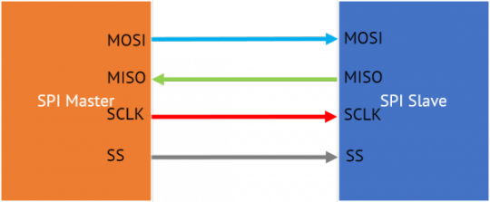
Figure shows the control lines and data lines of a single master-single slave SPI. The signal wires are MOSI, MISO, SCLK and SS. A MOSI signal is generated by the master device and it is received by the slave whereas a MISO signal is generated by a slave and received by the master. SCLK is the serial clock signal which is transmitted by the master to synchronise data transfer between the master and the slave. SS is the slave select signal which is transmitted to the chip select pin of the slave. It is an active low signal. MOSI signal is also named as serial data in (SDI) and MISO signal is named as serial data out (SDO). MOSI and MISO are data lines while SCKL and SS are control lines.
The pins are used according to the purpose. In case a device does not require an input, SDI pin may not be required and if a device does not require a output, SDO pin may not be present. Similarly if the communication is limited to one slave, then the CS pin on the particular slave device is grounded. In case of multiple slave operation, an SS signal is sent from the master to each slave device.
Working:
Most of the time, the communication will be between a single master and multiple slaves. The master generates a clock signal and using the slave select pin, it activates the slave device it wants to communicate with. The clock signal is provided to all slave devices if they are not selected for the communication at a particular time.
As discussed earlier, the master device initiates the communication. To initiate communication, the master generates clock signal which is of a frequency equal to or less than the maximum frequency the slave devices support. The slave device with which the communication has to be started is selected by pulling the chip select pin of the particular slave to low state. The slave devices which are not selected by the slave select signal will reject the clock signal as well as the MOSI signal. These slaves won’t generate the MISO signals.
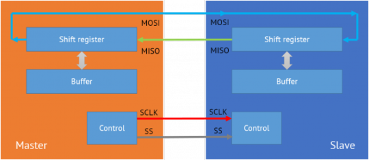
The slaves have tri-state outputs which go to high impedance state when the device is not selected. Chip-select pin of these devices without this tri-state outputs will not be activated and therefor they can not share the SPI bus with other devices. The data transmission is done in a full-duplex transmission mode. The data is sent by the master on the MOSI line and the slave reads it from the same line. Then the slave device sends a bit on the MISO line and the master reads it from the same line.
There data being transmitted are stored in shift registers associated with the master and the slave. When the master shift register shifts out a value through the MOSI line, the slave shifts the data into it’s register. While shifting data, MSB is the first one to be shifted out. After exchanging the data, the slave devices share the value and does the necessary operation. After the data transmission is done, the master stops generating the clock and the slaves are being rejected.
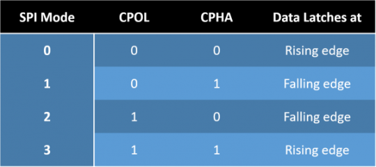
Clock Polarity and Phase:
Clock polarity and phase are the parameters which determine the edges of the clock. Apart from the clock frequency, the master should also configure the clock polarity and phase. Clock polarity will determine if the clock idles high or low, if it is 1 clock idles high and if 0 clock idles low. Clock phase determines when data is transmitted relative to the clock. It’s value also depends on clock polarity, both of these parameters creates different modes in SPI.
Based on the clock polarity and clock phase, there are four modes that can be used in an SPI protocol. If the clock phase is 0, the data is latched at the rising edge of the clock with polarity 0 and at the falling edge of the clock with polarity 1. If the phase of the clock is 1, data is latched at the falling edge of the clock with polarity 0 and rising edge with polarity 1.
Master-slave Configurations:
There are different ways in which the slaves can be attached to the master. Mainly there are two types of configurations commonly used. They are daisy chain configuration and parallel configuration.
Daisy Chain Configuration:
In cascaded or daisy chain configuration, the clock lines and chip select lines of all devices are connected together. The data from the master flows through each peripheral and returns to the master. The data output of the preceding slave devicee is attached to the data in of the next device. This will give a feel of a larger slave shift register. Only a single SS line is required by the master.
Daisy Chain Configuration
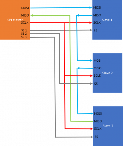
Independent Slave Configuration:
In independent slave configuration, the MISO line, MOSI lines and clock lines of all the devices are connected together. But the chip select pin of each peripheral is connected to separate slave select pins of the master.
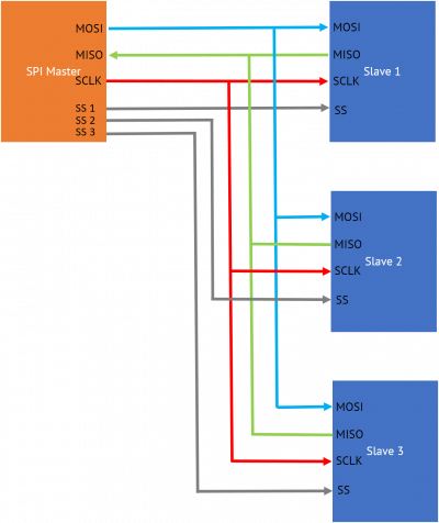
Independent slave configuration
Applications
SPI is a widely used protocol, so it is included in most of the microcontroller families. Atmel 8051 family and some AVRs use SPI for programmer communication. Some of the other chips using SPI are listed below.
Flash memories and EEPROMs, e.g: Microchip SST25VF080
SD/MMC Cards
Real Time Clock chips, e.g: Maxim DS1347
Aanalog to Digital converters, e.g: Microchip MCP3008
Battery management ICs, e.g: TI BQ76PL536
TFT LCD display drivers, e.g: ILI9341
Advantages of SPI
Supports multiple slave devices
Full duplex communication, transfer data in and out at the same time.
Significantly high data rates (in megabits/second) as compared to other serial communication stands, sometimes in megahertz range.
Simple protocol and easy to implement for single-master single-slave applications
Less complex circuitry and there is no need of external transceivers, so it is a very easy interfacing. It doesn’t care about physical interface specifications and voltage ranges.
Disadvantages
Required number of pins are high as compared to other serial protocols
Absence of in-chip addressing, it needs separate chip select of each devices
SPI doesn’t have an acknowledgement mechanism, so devices cannot confirm data reception and device existence.
SPI doesn’t have a flow control mechanism and it should be handled manually
It is a short distance communication by default, though there are solutions for extending for long-distance communication
0 notes
Photo

Raspberry PI mit analogem Temperatursensor LM35DZ Da der Raspberry PI über keine analogen Ein/Ausgänge verfügt muss man zusätzlich den Chip MCP3008 in die Schaltung integrieren. #raspberrypi #lm35dz #mcp3008 #temperatursensor #maker #electronic #components #diy #tech #techy #technology #DraegerIT (hier: Stefan Draeger Software) https://www.instagram.com/p/B2MyVumI3LQ/?igshid=19oxoppkrk95m
#raspberrypi#lm35dz#mcp3008#temperatursensor#maker#electronic#components#diy#tech#techy#technology#draegerit
0 notes
Text
Analog
Raspberry Pi does not include a hardware analog-to-digital converter, but an external ADC (such as the MCP3008) can be used to read external analog devices.

Tutorial: https://learn.adafruit.com/mcp3008-spi-adc/python-circuitpython
0 notes
Text
#Devember 2019 - Days 3 & 4
I’ve been studying the data sheets and articles on audio I/O. I’ve being studying the pi-pedal https://hackaday.com/tag/mcp3202/ that comes with some articles explaining some basic components usage with Raspberry. It also has a circuit analysis. I’ve noticed they use an op-amp for in and out, the MCP6002. Also they use a PWM for out, not a DAC. I’ve discovered that the voltage of the audio signal is very very low, below 200mV. So I need an op-amp (Operational Amplifier). I could have bought some MCP6002 together in the last order, but now I’d pay full shipping for a few Euros of ICs. I think I could set up a noisy op-amp with a few transistors. Tomorrow I’ll investigate more and decide if to order them.

I’ve wired up a circuit with a multiplexer and two of the MCP3008 of the day 1. I’m not sure about some details, being that I’m copying the circuit from https://www.mikronauts.com/raspberry-pi/raspberry-pi-analog-to-digital-conversion-experiments-and-howto/ but I have a different multiplexer, his pin naming is different from the one in the data sheet of his multiplexer, and I’m omitting for now some resistors, to try to understand why they are there. Regarding the code I’ve only separated the source of the mcp3008 test into a SPI library and a MCP3008 library. Tomorrow I’ll try to write the code to control the multiplexer and I’ll see it multiplexes SPI succesfuly.
Oh, I’ve also remembered that the GPIO is at 3.3V. Apparently it works with 5V but is discouraged. Luckily I have some bi-directional logic level converters I got some time ago. I think I’ll try to use the MCP3202 at 5V because it gets a double frequency in respect of with 3.3V (100kHz vs 50kHz), noise permitting. https://learn.sparkfun.com/tutorials/bi-directional-logic-level-converter-hookup-guide
1 note
·
View note