#gpio
Explore tagged Tumblr posts
Visit Tumblr Blog
Explore Tumblr blogs with no restrictions, modern design and the best experience.
Last Seen Tumblr Blogs


Fun Fact
Tumblr has a low social media market share in South America.
Text
Solenoids go clicky-clacky 🔩🔊🤖
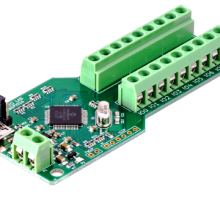
We're testing out an I2C-to-solenoid driver today. It uses an MCP23017 expander. We like this particular chip for this usage because it has push-pull outputs, making it ideal for driving our N-channel FETs and flyback diodes. The A port connects to the 8 drivers, while the B port remains available for other GPIO purposes. For this demo, whenever we 'touch' a pin on port B to ground, the corresponding solenoid triggers provide an easy way to check speed and power usage.
#solenoid#electronics#i2c#mcp23017#hardwarehacking#maker#embedded#engineering#robotics#automation#circuitdesign#pcb#microcontroller#tech#hardware#diyelectronics#electricalengineering#firmware#innovation#prototype#electromechanical#diy#electronicsproject#smarthardware#tinkering#gpio#fet#flybackdiode#programming#linux
44 notes
·
View notes
Text
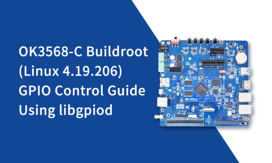
New Guide: GPIO Control with libgpiod on OK3568-C SBC
Easily manage GPIOs on the OK3568-C development board using libgpiod under Buildroot (Linux 4.19.206). Step-by-step commands, real examples, and tips to get started fast.
👉 Read the full guide here:
0 notes
Text
DIY Gate Sensor for Home Assistant
#Adafruit Feather#automation#binary sensor#DIY#door#electronics#ESP8266#gate#GPIO#Home Assistant#make#making#microcontroller#notification#sensor#smart home
0 notes
Text
General Purpose Input Output (GPIO) in Microcontroller
GPIO in Microcontroller: How General Purpose Input Output Works Hello, tech enthusiasts! In this blog post, I will introduce you to GPIO in Microcontrollers – one of the most essential concepts in embedded systems: GPIO (General Purpose Input Output). GPIO pins allow microcontrollers and processors to interact with external devices like LEDs, sensors, and buttons. They can be configured as input…
0 notes
Text

Raspberry Pi Projects for Electronics Engineering
Raspberry Pi is a small-sized, versatile single-board computer that has recently transformed electronics engineering by allowing millions of creative solutions. Its flexible form makes it suitable for use in applications such as prototyping, automation, and ofcourse IoT. Electronics enthusiasts can develop different projects such as home automation and robotics, thermal meters and energy saving gadgets. GPIO pins allow you to attach sensors, LEDs, motors and other periphery and make your ideas a reality. For instance, you can construct a simple weather station utilizing temperature and humidity sensitive devices and develop a security system with cameras and turn on motion indicators. Programmability of programming language with raspberry like Python and Scratch makes its usage easier and reduces complexity of the task. From this short introduction, people, who just start with electronics, and people, who design circuits or systems of considerable complexity, will find a lot of potential for both learning and creation with Raspberry Pi. It’s a place that has a great community and multiple resources that make it the perfect platform to learn practical electronics and use them to solve problems.
0 notes
Text
Understanding ESP32 Pin Configuration: A Developer's Guide
The ESP32 microcontroller has become a cornerstone of IoT development, thanks to its versatility and powerful features. One of the most crucial aspects of working with ESP32 is understanding its pin configuration and capabilities. Let's dive into the essential aspects of ESP32 pins that every developer should know.

GPIO Pins Overview
The ESP32 boasts up to 34 GPIO (General Purpose Input/Output) pins, but not all are available for use in most development boards. Some key points about ESP32 pins:
GPIO 6-11: Reserved for internal SPI flash connection
GPIO 34-39: Input-only pins with no internal pull-up/pull-down resistors
ADC Capabilities: Two 12-bit SAR ADCs, supporting 18 measurement channels
Touch Sensors: Up to 10 capacitive touch GPIOs
Special Function Pins
Several pins serve dual purposes or have specific functions:
Boot Mode Pins GPIO 0: Bootloader mode when pulled low during reset GPIO 2: Connected to on-board LED in many development boards
UART Pins GPIO 1 (TX) and GPIO 3 (RX): Default UART0 communication Often used for flashing and debugging
SPI Pins VSPI: GPIO 5 (CS), 18 (CLK), 19 (MISO), 23 (MOSI) HSPI: GPIO 14 (CLK), 12 (MISO), 13 (MOSI), 15 (CS)
Best Practices for Pin Usage
Strapping Pins Always check the strapping pin status before using GPIO 0, 2, 4, 5, 12, and 15. These pins may affect boot behavior if incorrectly configured.
Input-Only Pins When designing sensor interfaces, prefer GPIO 34-39 for analog inputs as they're input-only and less susceptible to noise.
Pull-up/Pull-down Configuration
ADC Usage ADC1: Can be used with Wi-Fi/Bluetooth active ADC2: Only available when Wi-Fi/Bluetooth is disabled
Common Pitfalls to Avoid
Don't use GPIO 6-11 in your projects as they're connected to the internal SPI flash.
Avoid using strapping pins for critical functions that can't be changed during boot.
Remember that GPIO 34-39 don't have internal pull-up/pull-down resistors.
Be cautious with voltage levels - ESP32 pins operate at 3.3V.
Conclusion
Understanding ESP32 pinout is fundamental for successful project development. By following these guidelines and best practices, you can avoid common issues and make the most of your ESP32's capabilities. Remember to always consult the official ESP32 technical reference manual for detailed specifications and updates.
#ESP32 #PinConfiguration #DevelopersGuide #Microcontrollers #EmbeddedSystems #IoT #Programming #Hardware #Electronics #Arduino #ESP32S2 #ESP32C3 #ESP32C2 #ESP32C6 #ESP32S3 #ESP32H2 #ESP32P1
#ESP32#microcontroller#pinconfiguration#GPIO#ADC#DAC#I2C#SPI#UART#PWM#analog#digital#input#output#microcontrollers#embeddedsystems#IoT#InternetOfThings#electronics#hardware#software#programming#development#Arduino#ESP8266#RaspberryPi#microcontrollerprogramming#embeddedprogramming#IoTdevelopment#electronicdesign
1 note
·
View note
Text
Phoniebox ~ RPi-Jukebox-RFID
Phoniebox is a contactless jukebox for the Raspberry Pi, playing audio files, playlists, podcasts, web streams and Spotify triggered by RFID cards. All plug and play via USB, no soldering iron needed. It also features GPIO buttons control support. github.com/MiczFlor/RPi-Jukebox-RFID
View On WordPress
0 notes
Text
GeeekPi Raspberry Pi Micro GPIO Terminal Block Breakout Board Module with LED
Questo e un terminale per GPIO dotato di morsetti a vite e led compatibile con la maggior parte dei Raspberry pi. Nella confezione di vendita oltre il terminale troviamo tutto il necessario per montarlo su Raspberry Pi. Premetto che sono appassionato di elettronica e ho in dotazione vari Raspberry Pi (dal 2B al 4 e Zero) e utilizzo spesso il GPIO per i miei progetti. Lo utilizzato per il…

View On WordPress
#diy#Electronics#Embedded systems#GeeekPi#GeeekPi accessories#GeeekPi product showcase#GeeekPi products#GeeekPi review#GeeekPi setup guide#GeeekPi tutorials#GeeekPi unboxing#GPIO#HAT#projects#Python programming#raspberry pi#Raspberry Pi accessories GeeekPi GPIO Terminal#Raspberry Pi community#Raspberry Pi enthusiasts#Raspberry Pi hacks#Raspberry Pi OS#Raspberry Pi projects#Raspberry Pi tips and tricks#Single-board computer#Tech Maker
0 notes
Text
A GPIO expander is a device that enables designers to implement additional inputs and outputs (I/O) on a microprocessor (MPU) or microcontroller (MCU) system.
0 notes
Text

Happy place
#tho u can tell its not going well bc im posting on tumblr instead of working on it#im emotionally dealing with the fact that im gonna have to be my own manual gpio pin on startup#its gonna be a uhhhhh situation#workable tho if i use the onboard to signal when i need to toggle the read write state#oh maybe it should be a button not a switch nvm we’re so back this’ll work
0 notes
Text

mini Sparkle Motion prototype - a tiny, fully-featured WLED board ✨🔌📏💡🌈
We're doing a lot of serious testing with our WLED mega-board, code-name Sparkle Motion .
While doing some holiday lighting projects, we also wanted something slim enough to slip into any design. It still uses an ESP32 for the best support, with USB-serial programming, 5A fuse, 5V level shifting + 100 ohm series resistors for pixel drivers, user/reset buttons, a user LED and onboard neopixel, JST SH analog/digital connector, QT I2C connector, 4 GPIO plus power/ground breakouts, and USB type C power/data input.
However, this version is made simpler and less expensive by dropping the DC jack and USB PD support: it's only for 5V strips if you want to power them directly (you could still drive 12V or 24V pixels, but you'll need separate power for them). Instead of a full set of terminal blocks for 3 signals, we only have two outputs, and they have to share the power and ground pins. It could also be used for a single two-pin dotstar LED setup. We kept the built-in I2S mic but dropped the on-board IR sensor - if you want an IR sensor, you'll be able to plug it into the JST SH port with a simple cable or solder it into the breakout pads.
The trade-off is that it's much smaller and slimmer, especially when no terminal blocks are soldered in by default: only 1.2" long x 0.785" wide (~1 sq in) x 0.3" thick vs. the original's 2" x 1.3" (2.6 sq in) x 0.55". To get it that small, we went 4-layer to give us a nice big ground and 5V plane in the middle and double-sided assembly. Coming soon.
#sparklemotion#wled#esp32#neopixel#holidaylighting#ledprojects#makers#electronics#prototyping#hardwaredesign#usbtypec#qtconnector#gpio#micromaker#slimdesign#techinnovation#ledcontroller#openhardware#adafruit#diylighting#iotprojects#esp32projects#compactdesign#ledenthusiast#holidaydecor#iotmaker#makercommunity#hardwarehacks#tinytech#ledlights
30 notes
·
View notes
Text
Ajitek Tech Solutions Pvt Ltd
1 note
·
View note
Text
You can just barely see it but the new @rickybabyboy circuit works (indicated by the led lighting up). This version of the circuit will let him interact with the conductive cloth of the circuit a couple feet away. Later I plan on hooking this up to the GPIO of one of the esp32 boards I have and setting up a pillow for Ricky to jump on and test this with
87 notes
·
View notes
Text
inserting a circuit, between her microcontroller gpio pins and her servo drivers, that randomises which gpio is driving which servo. watching her flail around hopelessly.
telling her that it's not random and if she tries hard enough she can figure the pattern out. of course, it is actually random and this is just a ploy to make her struggle harder.
@virtualgirladv
77 notes
·
View notes
Text
october 1st 2024: drafts!

preacher: i'm attaching slightly improved versions of our original drafts, but i'll also include mine and scott's garbage sketches under the cut because i think they're a little bit funny
(image id available through tumblr's accessibility options)
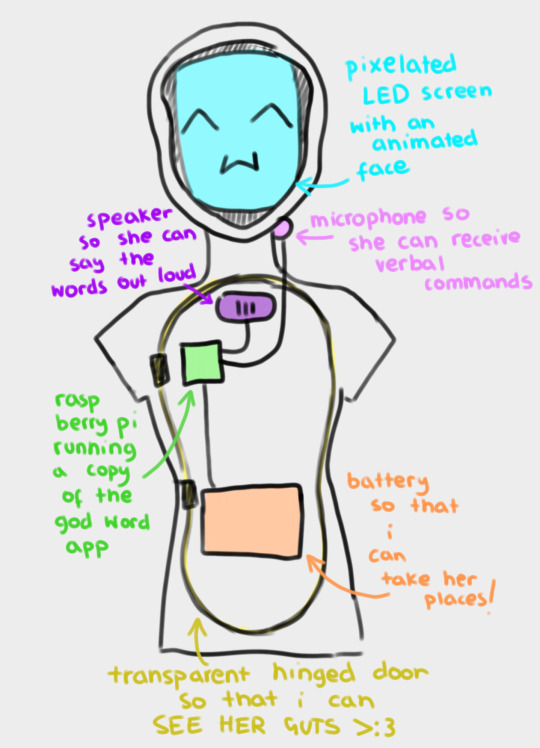
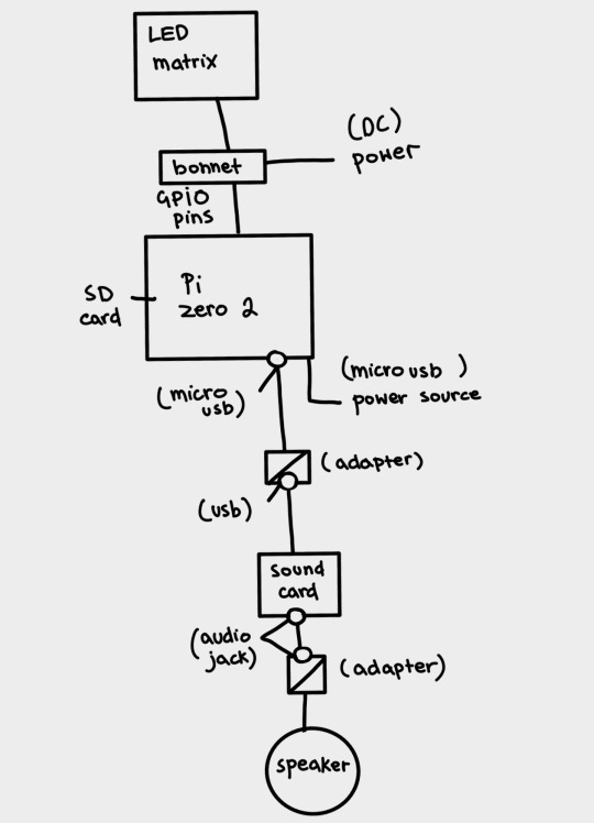
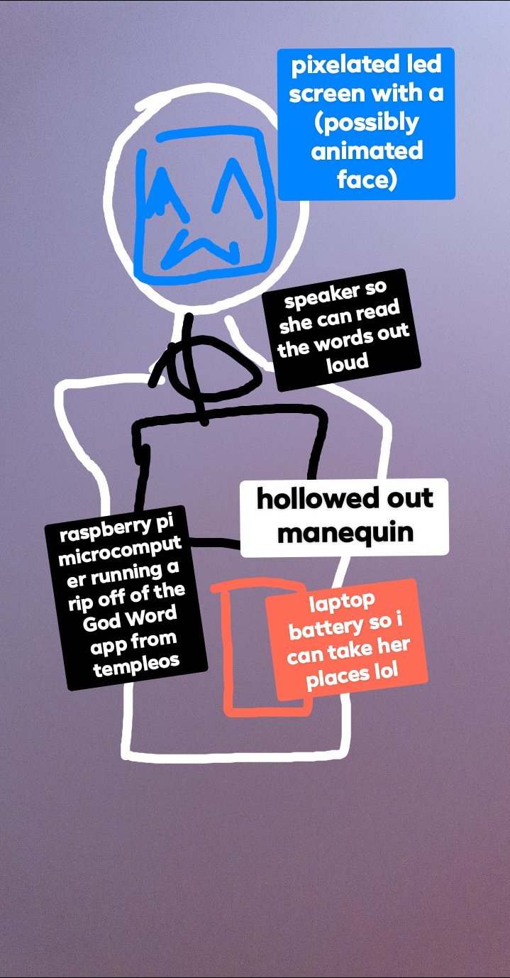
this is a slightly revised version of my original concept for "APRIL".
the main functionality i wanted for "APRIL" was for her to be able to read out words from the templeOS god word app, and ideally without needing keyboard input – hence the microphone. ideally all of her parts are going to fit inside a hollowed out mannequin or doll, which will probably just be the torso, so that she's more portable. for the same reason, i want her to run off a power bank – i want to be able to take her places!
if we manage, we're going to give her an animated LED face which moves to indicate when she's speaking. the way i first pitched it, i wanted it to also change a bit depending on how she "felt" – for example, frowning if the environment was hotter than ideal for the raspberry pi to operate on. but that's a bit beyond our current scope right now. i don't think we even ordered a thermostat.
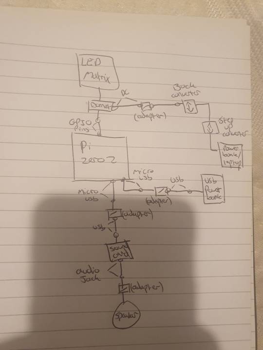
scott drew the following wiring diagrams based off my original sketch. here revised digitally for readability's sake.
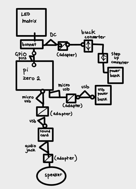
(image id available through the tumblr accessibility options although i fear it's not very good in this case. feedback appreciated).
scott: I decided to go with the raspberry pi zero 2w because it's what I've got experience coding on, it's relatively cheap for the "brains" of the operation (heh) and can perform both tasks from the godword prophecy generation, speaker operation and led matrix operation simultaneously. Plus its small enough to keep the circuit lightweight and fit inside the initial mannequin design.
This drawing fits no kind of engineering standard by the way lol. It was an initial sketch closer to a wiring diagram to see how it'd physically setup and wrap my head around transforming it from mains power to being theoretically portable and running on powerbanks. Unfortunately the LED matrix is really fucking power hungry so needs its own power supply of really specific voltage and current draws hence all the converters.
Also because Im using the smaller and cheaper pi, as oppossed to a stronger system like the pi4, it doesn't have any audio out jack so I plan to use the micro usb for audio out which means yet again I need another adapter for a soundcard and usb to micro usb adapters and all that jazz. Usually sound out can be done through the GPIO pins but the LED matrix takes so many pins that I cant really take anything form them so I had to look for other ways of doing it. Plus this way I get to add a soundcard so if we wanna add microphone support or anything later on we can :)
(Also this is all a little obtuse because I'm trying to do it as much as plug and play and screw terminal style as possible rather than actually solder connections for ease of access and initial setup, but this also works for modular design and component swapping later too so its cool.)
preacher: another reason we're going with plug&play is becauuseeeeee i don't own a soldering iron 😭 it's ok. it's ok.
our silly initial drafts under the cut for your viewing pleasure.
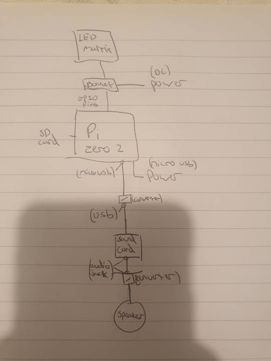
preacher: these were made around 2 weeks ago, so about september 15th ish.
as you can see the first "APRIL" drawing was beautifully drawn with my fat fingers in the facebook messenger photo editor. i think it holds up. lol.
#computers#computer#programming#software engineering#robots#robotics#raspberry pi#robot girl#machine#machines#divine machinery#tech#technology#techcore#machinecore#objectum#objectophilia#robophilia#techum#technum#android#gynoid#mechanical divinity#templeos#coding#scott#preacher#drafts#update#roadmap
30 notes
·
View notes
Text
GPIO good pup in/out
26 notes
·
View notes