#Optocoupler relay module
Explore tagged Tumblr posts
Visit Tumblr Blog
Explore Tumblr blogs with no restrictions, modern design and the best experience.
Last Seen Tumblr Blogs


Fun Fact
After the announcement of the deal with Yahoo!, there were 170K signatures of unhappy Tumblr users petitioning to prevent the sale in 2013.
Text
Optocoupler relay, isolated circuit, Optocoupler circuit, High voltage optocoupler
DIP6 SMT 1 Channel 400 V 4170 Vrms Zero-Cross Triac Optoisolator
#Optoelectronics#Isolation Components#Optocouplers#MOC3043SR2M#Onsemi#opto-isolator module#Triac opto isolator#Phototransistor Optocoupler#High speed#switch#Optocoupler relay module#isolated circuit#circuit#High voltage
1 note
·
View note
Text
https://www.futureelectronics.com/p/semiconductors--optoelectronics--isolation-components-optocouplers/fod817dsd-onsemi-3492428
Thermal Heat sink, optocoupler relay module, Opto-isolator module
DIP4 Surface Mount Single Channel 70 V 5000 Vrms Phototransistor Optocoupler
#Optoelectronics#Isolation Components#Optocouplers#FOD817DSD#onsemi#Thermal Heat sink#relay module#Opto-isolator module#Phototransistor#optoelectronics#Thermal management#switch#Optical sensors#optocoupler relay
0 notes
Text
This 16 Channel Relay Module consists of sixteen 5V relays and each one of the individual relay needs 15-20mA driver current. This module has a light coupling protection (optocoupler) which provide opto-isolation for safety purposes. This is a Relay module of 16 channel interface board that can be control various appliances, and other electronic equipment with large current. It can be controlled by Micro-controllers like Arduino, Raspberry-pi, ARM, TTL logic directly.
3 notes
·
View notes
Text
BMS Safety Design: Best Practices for Preventing Battery Hazards
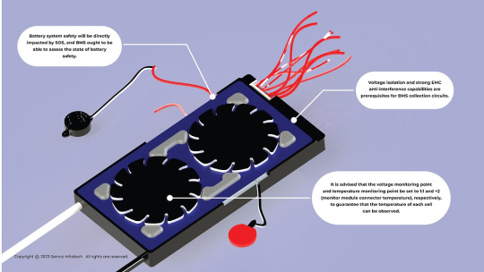
Voltage isolation and strong EMC anti-interference capabilities are prerequisites for BMS collection circuits. Special integrated circuits are generally not advised because they cannot achieve fault diagnosis, accuracy, passive equalization, or high-precision AD conversion. Examples of these circuits include optocoupler relay + external AD, data processing, passive equalization, drop monitoring, and high anti-interference ability. They are hard to guarantee, and they are not very resistant to interference.
It is advised that the voltage and temperature monitoring points be set to 1:1 and +2 (monitor module connector temperature), respectively, to guarantee that the temperature of each cell can be observed. Temperature monitoring points must also be installed on the battery pole to reduce the temperature monitoring delay and increase accuracy. Incorporate temperature monitoring at critical locations that are prone to overheating, like circuit breakers, relays, and power bus connection points.
Battery system safety will be directly impacted by SOS, and BMS ought to be able to assess the state of battery safety. It is impossible to determine the actual temperature inside the battery because temperature monitoring is either not done at this time or is limited to measuring the temperature of the confluence. As a result, there is a serious hidden risk to the battery’s safe operation when the heat inside the battery gets out of control and the rapidly rising temperature is not noticed in time.
Likewise, in the event that both the battery temperature and internal pressure rise too high, the safety valve will open. However, since safety valve monitoring is currently lacking, preventive actions such as shutting off the circuit, halting operation, initiating local cooling, and initiating firefighting cannot be taken in a timely manner. As a result, the two points mentioned above will eventually lead to breakthroughs in BMS security design.
Energy Storage BMS Development Trend
As monomer battery capacity increases, battery imbalance becomes more severe.
Passive equalization technology is no longer sufficient to balance battery systems and extend battery life.
Active equalization technology is an inevitable trend in the development of energy storage BMS.
Active equalization can extend battery life by 20%, which has high economic benefits.
Development Trend of Energy Storage BMS Battery Sensing Technology
The development of battery sensors and wireless BMS has become a priority due to the swift advancement of this technology. Future research and discussion on BMS are critically needed.

Problems with the technology of the current battery management system. There are obstacles in the way of technological advancement for the current battery management system:
1. There are two unsolvable issues because the voltage and temperature recorded by the current battery management system are the external parameters of the cell.
(a) Because the battery’s internal temperature cannot be measured, it is impossible to accurately determine how hot it gets inside. As a result, in the event of a small internal short circuit or thermal runaway cell, prompt safety warning and protection are not possible. This is a really big issue. The temperature inside the battery can be used to predict the thermal runaway of the battery in advance, preventing many combustion and explosion accidents that have happened in electric cars and energy storage power plants.
However, the system has experienced thermal runaway precisely as a result of the temperature gradient’s influence and the delay in temperature sampling. It’s too late to issue warnings and safeguards. This problem, which must be resolved immediately, is connected to the battery system’s safety.
(b) It is impossible to precisely determine the true state of the battery, including its capacity, health, attenuation, safety status, etc., since the real temperature and other state parameters inside the battery cannot be obtained.
2.The current battery management system must gather wire harness data to gather parameters like voltage, temperature, and other data. Numerous failure hazards, including poor contact, will arise because of the numerous geranium beams, sampling points, and connectors attached to the wire harness. In addition, it will result in production issues, insulation deterioration, and power leaks brought on by wire harness aging, damage, or extrusion. The system’s potential safety risk.
3. Since wire harness installation is typically done by hand, production and installation costs will inevitably rise.
4. Ineffective cell detection in the absence of installation and operation; damage to the battery; and thermal runaway safety.
Energy storage BMS development is moving in the direction of active equalization technology. This is because active equalization, particularly for large-capacity battery systems, can more successfully balance battery systems and increase battery life. Because active equalization technology can increase battery life by up to 20%, it offers significant economic benefits.
Since batteries account for a large portion of the cost of energy storage systems, this represents substantial savings for users of energy storage. Active equalization technology is where energy storage BMS development is trending. This trend is advantageous since it will result in energy storage systems that are more dependable and efficient.
#Battery Hazard Prevention#Battery Management System (BMS) Safety#Battery Safety Hazards#BMS Best Practices#BMS Safety Design
0 notes
Link
Find obsolete, discontinued, EOL, Last time Buys, Hard to find, and long lead time electronic products in stock/available. Immediate Price and Delivery.
Request A Quote Click Here
TYPES OF ELECTRONIC PRODUCTS
Audio ICs
Amplifier ICs
Chipsets
Clock & Timer ICs
Communication ICs
Networking ICs
Counter ICs
Data Converter ICs
Digital Potentiometer ICs
Driver ICs
Interface ICs
Integrated Circuits
Logic ICs
Microprocessors
Microcontrollers
Multimedia ICs
Power Management ICs
Programmable Logic ICs
Switch ICs
Semiconductors
Wireless ICs
RF Integrated Circuits
Memory ICs
Audio & Video Connectors
Automotive Connectors
Backplane Connectors
Board to Board Connectors
Card Edge Connectors
Circular Connectors
Connectors Obsolete
D-Sub Connectors
Ethernet Connectors
FFC/FPC Connectors
Fiber Optic Connectors
IEEE 1394 Connectors
I/O Connectors
Lightning Connectors
Memory Connectors
MIL-Spec / MIL-Type Connectors
Modular Connectors
Mezzanine Connectors
Photo-voltaic Connectors
Pin & Socket Connectors
Power Connectors
RJ45 Connectors
Solar Connectors
USB Connectors
Industrial semiconductors
Industrial Integrated Circuits
Industrial Capacitors
Industrial Connectors
Industrial Controllers
Industrial Counters
Industrial Relays
Industrial Solenoids
Industrial Sensors
Industrial Switches
Industrial Terminal Blocks
Industrial Timers
Industrial microprocessors
Industrial obsolete Parts
Industrial Components
Industrial Electronics
Backlighting Components
Electronic Visual Displays
Electronic Drivers
Fiber Optics
LED Emitters
LED Indication
LED Lighting
Optical Detectors and Sensors
Optical Switches
Optocouplers
Photocouplers
Flash memory
FPGA - Configuration Memory
FPGA - Field Programmable Gate Array
Managed NAND
Memory Controllers
Obsolete DRAM Memory
Memory IC Development Tools
Memory Cards
NVRAMs
NAND Flash
NOR Flash
Obsolete SRAM Memory
Simm
SO Dimm
Dimm
Transflash memory module
Memory Modules
Audio Transformers
Signal Transformers
Capacitors
EMI Filters
EMI Suppression
Encoders
Ferrites
Filters
Timing Devices
Potentiometers
Trimmers
Rheostats
Resistors
Thermistors/NTC
Thermistors/PTC
Varistors
Audio Sensors
Current Sensors
Environmental Sensors
Flow Sensors
Magnetic Sensors
Motion & Position Sensors
Optical Sensors
Pressure Sensors
Proximity Sensors
Temperature Sensors
MIL-STD-883
Mil Spec Resistors
Mil Spec Capacitors
Mil Spec Semiconductors
Mil Spec Integrated Circuits
Mil Spec Ics
Mil Spec Connectors
M39006 Series
M83733 Series
SNJ55 Series
SNJ54 Series
5962 Series
54F Series
MS3349 Series
5945-00 Series
MS310 Series
JAN/JANTX Series
JANTXV Series
JM38510 Series
285 notes
·
View notes
Text
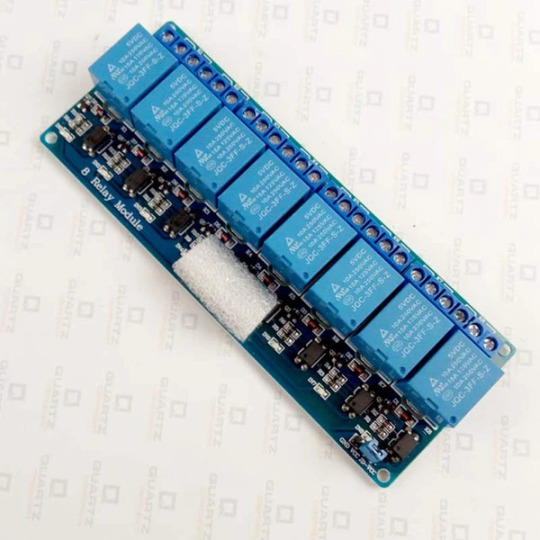
8 Channel 5V Relay Module with Optocoupler
Relays are important part of any electrical and electronic circuits. We use relays in control applications, switching applications, circuit protection applications and load transfer applications. Relays are also used to provide electrical isolation between two circuits.
Buy this Relay Module: https://quartzcomponents.com/products/8-channel-5v-relay-module-with-optocoupler
1 note
·
View note
Video
instagram
🇧🇷 Em breve mais um lançamento da Projetos Eletrônicos Maker !!!! Rele Board 8 - Placa com 8 reles, proteção por optoacopladores, borne para alimentação auxiliar e módulo I2C opcional !!!! Vamos para a montagem !!! ---------------------------------- 🇺🇸 Soon another launch of Electronic Projects Maker !!!! Rele Board 8 - board with 8 relay, optocoupler protection, auxiliary Power and optional I2C module !!!! Let's go to the assembly ---------------------------------- #releboard8 #rele #relay #i2c #optoacoplador #eletrônica #eletronica #desenvolvimento #projeto #engineering #engenharia #maker #makers #diy #geek #arduino #arduinouno #arduinonano #microcontrolador #pic #walproj #projetosmaker #projetoseletronicos #hardware #iloveeletronics #proteus #protótipo (em Projetos Eletronicos) https://www.instagram.com/p/B8IIqOuhZI7/?igshid=1f0w1yh6gu6oe
#releboard8#rele#relay#i2c#optoacoplador#eletrônica#eletronica#desenvolvimento#projeto#engineering#engenharia#maker#makers#diy#geek#arduino#arduinouno#arduinonano#microcontrolador#pic#walproj#projetosmaker#projetoseletronicos#hardware#iloveeletronics#proteus#protótipo
1 note
·
View note
Text
This 16 Channel Relay Module consists of sixteen 12V relays and each one of the individual relays needs 15-20mA driver current. This module has coupling protection (optocoupler) which provides opto-isolation for safety purposes. This is a Relay module of 16 channel interface board that can be control various appliances, and other electronic equipment with a large current. It can be controlled by Micro-controllers like Arduino, Raspberry-pi, ARM, TTL logic directly.
2 notes
·
View notes
Text
Mengetahui Relay Serta Trik Kerjanya
Dalam sejumlah proyek electronica serta IoT kadangkala dibutuhkan buat mengatur suatu fitur, contohnya lampu taman atau buat menyalak serta mati berdasar pada triger dari mikrokontroler. Buat kebutuhan itu, diperlukan suatu fitur yang memiliki fungsi sama dengan sakelar automatic yang bisa melaksanakan switch ON serta OFF buat mengantarkan tegangan 220 AC ke lampu taman, berdasar pada input dari tanda DC mikrokontroler.
Apabila pembaca sementara itu melakukan proyek yang kira-kira sama, jadi anda saat ini butuh apa yang disebut yaitu Relay. Relay pada dasarnya yaitu sakelar yang mempertautkan serta memutus arus listrik berdasar pada suatu tanda pecut kekangan dari fitur electronic yang lainnya. Pada intinya ada dua macam relay, ialah
Relay elektromekanis

Relay yang memanfaatkan dasar elektromagnetik buat gerakkan contact sakelar. Pada sisi pertama tulisan ini, bakal fokus pada macam relay satu ini
Relay Padu State

Relay yang memanfaatkan technologi semikonduktor (optocoupler) buat melaksanakan switch ON serta OFF. Pengkajian terkait RSS bakal dikaji di sisi ke 2. Relay di wujud mulanya sebatas relay elektromekanis, dijumpai di tahun 1835 oleh Joseph Henry dalam suatu demonstrasi di College of New Jersey.
Henry memanfaatkan sebagian kecil type elektromagnetik buat menswitch sakelar ON serta OFF, serta memperkirakan kalau fitur itu bisa dipakai buat mengatur fitur electronic dari jauh.
Henry setelah itu menempatkan inspirasi penemuan itu ke penemuannya yang lainnya, ialah telegraf electronic yang sukses ditingkatkan setelah itu oleh William Cooke serta Charles Wheatstone dari Inggris, pun oleh Samuel F. B. Morse dari Amerika Serikat. Relay setelah itu dipakai di switching telpon serta pc electronic waktu - waktu awalan sebelumnya transistor dijumpai diakhir 1940.
Relay elektromekanis memanfaatkan sisi yang bergerak buat mempertautkan contact dengan bagian output dari relay. Gerakan contact ini berasal dari medan elektromagnetik dari tanda input daya rendah, maka menimbulkan mengucurnya serangkaian dialiri dengan arus mempunyai daya tinggi. Bagian fisik yang bergerak itu yang membikin bunyi "klik" waktu relay switch dari OFF ke ON.
Modul Relay Elektromekanis

Modul relay elektromekanis yang sering dipakai serta siap di pasar kebanyakan punya macam low tingkat penggerak atau high tingkat penggerak. Relay low tingkat penggerak butuh pecut tanda pemikiran 0 buat menghidupkan relay, sementara itu high tingkat penggerak butuh tanda pemikiran 1 buat menghidupkan relay.
Akan tetapi apabila pembaca butuh suatu modul relay yang bisa dipakai buat low tingkat penggerak serta high tingkat penggerak, pembaca bisa coba modul relay seperti gambar di bawah.
Buat mencoba modul relay, embeddednesia memanfaatkan modul Arduino UNO, dengan program blinky di di PIN 13 apabila pin IN dikaitkan dengan PIN13 serta jumper relay dikonfigurasi high penggerak jadi hidup Led built-in bakal sama dengan sinyal di relay, sama dengan percobaan yang dinarasikan di video berikut Pada sisi ke dua judul ini, penulis bakal membicarakan macam relay yang memiliki nama Padu State Relay.
Cari Dan Temukan Komponen Elektronik Trigger Devices Untuk Industri Dan Pabrikasi, Bahkan Trigger Devices Yang Usang Ataupun Trigger Devices Yang Sulit Ditemukan.
0 notes
Text
5 Relay Module Circuit Designs You Can Build With A Soldering Iron
Introduction
A relay is an electromagnetic switch used to turn on or turn off a circuit. It consists of an electromagnet (a coil of wire that becomes magnetic when current flows through it) and a set of contacts. The electromagnet activates the contacts to either make or break the connection in the circuit. Relay modules are boards that house one or more relays along with the necessary components to control them. In this post, we will show you five different relay module circuit designs that you can build at home with a soldering iron.
Basics of a Relay Module
In order to understand how a relay module works, it is important to know the basics of a relay. A relay is an electrically controlled switch that can be used to turn on or turn off a circuit. A relay module is a device that contains one or more relays. Relay modules are available in a variety of shapes and sizes, but they all have three basic components: terminals, a coil, and a switch. The terminals are where the electrical connection is made to the load (the device that will be turned on or off by the relay). The coil creates a magnetic field when electricity is flowing through it, and this magnetic field activates the switch. The switch is what actually turns the load on or off. When choosing a relay module circuit for your project, there are several things to keep in mind. First, you need to decide how many channels you need. One channel can control one circuit, so if you have multiple circuits that you want to control with your relay module, you will need more than one channel. Second, you need to decide what voltage you will be using. Relay modules are available in both low voltage (5V) and high voltage (12V) versions. Finally, you need to decide what type of switching you need: SPDT (single pole double throw) or DPDT (double pole double throw). SPDT modules can only control one circuit at a time, while DPDT modules can control two circuits simultaneously
Types of Relay Modules
There are two main types of relay modules: those with an optocoupler and those without. Optocouplers provide electrical isolation between the control circuit and the load circuit, which can be helpful in preventing voltage spikes and other electrical issues. Relay modules without optocouplers are typically less expensive, but they may not provide the same level of protection against electrical problems.
How to Build a Relay Module Circuit
Building a relay module circuit is not difficult, but it requires some basic understanding of electronics. Here are the steps: 1. gather the necessary components: a soldering iron, solder, wire, a breadboard, and the relay module. 2. Solder two wires to the terminals of the relay module. 3. Connect one end of each wire to the power supply (batteries work fine). The other ends of the wires will be connected to the load (the device you want to control with the relay). 4. Place the relay module on the breadboard so that the wires are not touching each other or any other components. This will prevent shorts. 5. Connect one wire from the power supply to one of the outer legs of the transistor on the relay module (this will be your trigger signal). The other wire from the power supply can go to any other point on the transistor leg or to ground. 6. To test your circuit, apply voltage to the trigger signal wire and observe that current flows through to your load (you may need an ammeter for this). If everything is working properly, you can now build your final circuit on a more permanent medium such as perf board or strip board.
Tips for Building Relay Module Circuits
1. When soldering the relay module to your circuit board, be sure to use a good quality solder. This will ensure that the connection is strong and won't come loose over time. 2. Make sure that the exposed wires on the relay module are insulated. This will prevent them from accidentally touching and shorting out your circuit. 3. If you're using a breadboard to build your circuit, be sure to use long jumper wires to connect the relay module. This will prevent the breadboard from becoming overloaded and causing problems with your circuit. 4. Once you have your circuit built, test it out before connecting it to any power source. This will ensure that everything is working properly and that there are no shorts or other issues that could cause problems down the road.
Conclusion
With a little bit of creativity and a soldering iron, you can build any one of these relay module circuit designs. Each design has its own unique features and benefits, so be sure to choose the one that best suits your needs. And if you're feeling really ambitious, why not try building all five? Explore More
0 notes
Link
0 notes
Link
Electronic Products Distributor
ELECTRONIC PRODUCTS DISTRIBUTOR - PRECISION LOGIC
Find obsolete, discontinued, EOL, Last time Buys, Hard to find, and long lead time electronic products in stock/available. Immediate Price and Delivery.
CALL US 516-826-6200
TYPES OF ELECTRONIC PRODUCTS
Audio ICs
Amplifier ICs
Chipsets
Clock & Timer ICs
Communication ICs
Networking ICs
Counter ICs
Data Converter ICs
Digital Potentiometer ICs
Driver ICs
Interface ICs
Integrated Circuits
Logic ICs
Microprocessors
Microcontrollers
Multimedia ICs
Power Management ICs
Programmable Logic ICs
Switch ICs
Semiconductors
Wireless ICs
RF Integrated Circuits
Memory ICs
Audio & Video Connectors
Automotive Connectors
Backplane Connectors
Board to Board Connectors
Card Edge Connectors
Circular Connectors
Connectors Obsolete
D-Sub Connectors
Ethernet Connectors
FFC/FPC Connectors
Fiber Optic Connectors
IEEE 1394 Connectors
I/O Connectors
Lightning Connectors
Memory Connectors
MIL-Spec / MIL-Type Connectors
Modular Connectors
Mezzanine Connectors
Photo-voltaic Connectors
Pin & Socket Connectors
Power Connectors
RJ45 Connectors
Solar Connectors
USB Connectors
Industrial semiconductors
Industrial Integrated Circuits
Industrial Capacitors
Industrial Connectors
Industrial Controllers
Industrial Counters
Industrial Relays
Industrial Solenoids
Industrial Sensors
Industrial Switches
Industrial Terminal Blocks
Industrial Timers
Industrial microprocessors
Industrial obsolete Parts
Industrial Components
Industrial Electronics
Backlighting Components
Electronic Visual Displays
Electronic Drivers
Fiber Optics
LED Emitters
LED Indication
LED Lighting
Optical Detectors and Sensors
Optical Switches
Optocouplers
Photocouplers
Flash memory
FPGA - Configuration Memory
FPGA - Field Programmable Gate Array
Managed NAND
Memory Controllers
Obsolete DRAM Memory
Memory IC Development Tools
Memory Cards
NVRAMs
NAND Flash
NOR Flash
Obsolete SRAM Memory
Simm
SO Dimm
Dimm
Transflash memory module
Memory Modules
Audio Transformers
Signal Transformers
Capacitors
EMI Filters
EMI Suppression
Encoders
Ferrites
Filters
Timing Devices
Potentiometers
Trimmers
Rheostats
Resistors
Thermistors/NTC
Thermistors/PTC
Varistors
Audio Sensors
Current Sensors
Environmental Sensors
Flow Sensors
Magnetic Sensors
Motion & Position Sensors
Optical Sensors
Pressure Sensors
Proximity Sensors
Temperature Sensors
MIL-STD-883
Mil Spec Resistors
Mil Spec Capacitors
Mil Spec Semiconductors
Mil Spec Integrated Circuits
Mil Spec Ics
Mil Spec Connectors
M39006 Series
M83733 Series
SNJ55 Series
SNJ54 Series
5962 Series
54F Series
MS3349 Series
5945-00 Series
MS310 Series
JAN/JANTX Series
JANTXV Series
JM38510 Series
102 notes
·
View notes
Text
5V-4 Channel Relay Board - Module - No Optocoupler - LED For Arduino PIC-ARM-AVR Smart Home Automation Modules
5V-4 Channel Relay Board - Module - No Optocoupler - LED For Arduino PIC-ARM-AVR Smart Home Automation Modules

5V-4 Channel Relay Board - Module - No Optocoupler - LED For Arduino PIC-ARM-AVR Smart Home Automation Modules
Price
1.79 Catch me HERE
0 notes
Text
2 relay modules with optocoupler isolation, support high and low level triggering, one relay expansion board 5V
2 relay modules with optocoupler isolation, support high and low level triggering, one relay expansion board 5V

2 relay modules with optocoupler isolation, support high and low level triggering, one relay expansion board 5V
Price
1 Catch me HERE
0 notes
Text
Relays are important part of any electrical and electronic circuits. We use relays in control applications, switching applications, circuit protection applications and load transfer applications. Relays are also used to provide electrical isolation between two circuits. This 2-channel Relay module comes with Optocoupler protection is an active low relay module which means that the relay will conduct when the input signal falls below 2V and if it is above 2V then the relay is turned off you can also make it an active module by changing the jumper position on the power module.
2 notes
·
View notes
Link
Application: 1. 24V relay contact capacity 10A 250V with optocoupler protection. The onboard power supply module does not require an external power supply. The I/O port drive is active low. 2. ...
0 notes