#PIR sensor tutorial without Arduino
Explore tagged Tumblr posts
Visit Tumblr Blog
Explore Tumblr blogs with no restrictions, modern design and the best experience.
Last Seen Tumblr Blogs


Fun Fact
Tumblr has a low social media market share in South America.
Text
youtube
Proximity sensing is a very common application in electronics. There are several ways to accomplish this. The most common way is by using a PIR sensor. PIR Sensor senses the change in ambient infrared radiation caused by warm bodies. I have already covered this in my Tutorial No. 5: "PIR Sensor Tutorial - With or Without Arduino". However, since PIR sensors detect movement from living objects, they can generate false alarms. These sensors are also inefficient in hot environments, as they rely on heat signatures.
The other common methods of proximity sensing involve, using reflected ultrasonic or light beams. Using these sensors, the intruding object is detected by the reflected beam back to its source. The time delay between transmission and reception is measured to calculate the distance to the object. In this tutorial, we are going to look at another method of proximity sensing using "Microwaves" and "Doppler Effect". In my hand is an inexpensive RCWL-0516 Microwave Radar Motion Sensor. The RCWL-0516 microwave sensor detects "any movement" from "any object" and does not rely on heat, making it more reliable in hot environments. I am going to use this sensor to create a Geo-fence around my house to detect motion and get notifications.
3 notes
·
View notes
Text
In Tinkercad circuits, choose sensor substitutes.

Tinkercad Circuits has a small library of frequently used electronic parts by design. Beginners may easily explore the complexities of the electrical world without feeling overwhelmed thanks to this curation. The drawback is that you can't build an identical replica of your circuit in the simulator if you're looking for a particularly specific part number or version of a sensor that isn't there in the parts drawer.
Fortunately for all of us, there's usually a solution to represent your missing component by using a similar one instead. A few major groups of sensors contain many similar sensors. You can choose an appropriate replacement for your Tinkercad Circuit with the aid of this tutorial.
Digital sensors

As they are activated, analogue sensors provide a changing voltage and resistance. Potentiometers are the most common sort of analogue sensor, but other more specialised varieties exist as well, such as flex sensors, photoresistors, microphones, some temperature sensors, force-sensitive resistors (pressure sensors), piezo components, and some IR distance sensors. Analogue inputs can be read using Arduino's analogRead() function or Tinkercad's "read analogue pin" block.
We advise using a potentiometer or TMP36 temperature sensor as an alternative in Tinkercad circuits if the analogue sensor you wish to use has three pins, as they both have three pins (power, ground, and signal). The TMP36 requires a regulated power supply voltage (2.7-5.5V), whereas a potentiometer is an only resistive sensor. This is an important distinction to make.
The only viable alternative in Tinkercad Circuits if your analogue sensor only has two pins is a two-pin photoresistor (the piezo element in Tinkercad Circuits can only be used as an output).
Electronic Sensors

High/low voltage signals and more complicated digital signals are the two primary categories of digital sensors.
Pushbuttons, switches, tilt ball sensors, magnetic reed switches, PIR motion sensors, and vibration switches are a few examples of sensors in this category. Try one of the many switches and pushbuttons available in Tinkercad Circuits, but also have a look at the tilt sensor and PIR motion sensor, whose simulations might more precisely resemble whatever digital sensor you are trying to replicate. Using digitalRead();, Arduino may read signals with high or low voltage. "Read digital pin" is the Tinkercad block for digital inputs. Launch the simulation below, then click on each sensor to see what happens:
The swap possibilities are more constrained for more sophisticated sensors that make use of data protocols like i2c. There isn't a component that can act as your i2c device, yet you might be able to use the extra library by putting it into your Arduino sketch.
Further Resources
When you make a substitution, we advise using the annotation tool to put notes on your circuit. Even though you couldn't illustrate the precise correct component, this can still aid in communicating the intent.
Don't overlook Tinkercad Circuits' starters, which can get you up and going with several fundamental sensors very quickly (in the components drawer).
Try out our beginner-level Arduino courses using Tinkercad Circuits to learn more about how to add sensors into your Arduino projects.
Send the team your requests for components, please! Although we deliberately limit the number of available components, we are constantly considering what we can add to make Tinkercad Circuits even better. Your criticism is a gift. I'm grateful.
1 note
·
View note
Text
ESP32 Arduino Tutorial: PIR motion sensor and interrupts
Introduction
In this esp32 tutorial we will check how to interact with a PIR motion sensor using an interrupt based approach, using the Arduino core running on the ESP32.
In the previous tutorial, we covered the basics on how to interact with the PIR sensor. Nonetheless, we followed a polling approach, which involves periodically checking the state of the sensor data pin connected to the ESP32. If it is in a HIGH state, then it means some movement is currently being detected.
Nonetheless, we can rely on the transition from LOW to HIGH in the data pin of the sensor when motion is detected to trigger an interrupt on the ESP32, thus signaling the event. That way, we avoid polling and we can use those computation cycles to do something more useful in our program.
To achieve this, we will need to use some FreeRTOS primitives, more precisely semaphores. You can read here a previous post about semaphores using the Arduino core and the ESP32.
Semaphores are typically used to guarantee mutual exclusive access to resources shared amongst tasks and also for synchronization purposes.
In our case, we are going to make the main task that is executing our code (in this example, it will be the Arduino loop) block in a semaphore call. While this task is blocked, the FreeRTOS scheduler can allow other tasks to execute.
Then, when an interrupt occurs, we will basically release the semaphore so, when the interrupt finishes, the task will unblock and execute the logic associated with the detection of motion.
In this tutorial we will use a DFRobot’s PIR sensor module, which already contains all the electronics we need to connect the sensor to a microcontroller and start using it. Please check here for the connection diagram to the ESP32.
The tests were performed using a DFRobot’s ESP32 module integrated in a ESP32 development board.
The code
We start our code by declaring a global variable to hold the number of the GPIO of the ESP32 that will be connected to the sensor. This way, we can easily change it later if needed.
const byte interruptPin = 22;
Then, we need to declare a semaphore also as a global variable, so it can be accessed by both the interrupt service routine and the main code.
SemaphoreHandle_t syncSemaphore;
Moving on to the Arduino setup, we start by opening a serial connection to output the results of executing our program.
Serial.begin(115200);
Next, we will create the semaphore. Since we are just doing some simple synchronization, we don’t need to create a counting semaphore and we can create a binary semaphore instead.
Note that although a binary semaphore can be seen as a mutex, there are actually some differences that you can read here. Nonetheless, for synchronization purposes like the one we are implementing, the recommended primitive to use is a binary semaphore [1].
So, to create a binary semaphore, we simply need to call the xSemaphoreCreateBinary function, which takes no arguments and will return a SemaphoreHandle_t value. This is an handle that we will use to reference the semaphore in the related function calls.
Note that it is important to create the semaphore before attaching the interrupt to make sure the interrupt service routine doesn’t start to use the semaphore before it is initialized.
syncSemaphore = xSemaphoreCreateBinary();
Since we are going to work with a GPIO operating as input, we need to declare its operation mode as such.
To do it, we call the pinMode function, passing as first input the number of the pin and as second the operation mode. We are going to use the INPUT_PULLUP to guarantee that the pin will be at a known state (VCC) when no signal is applied. Otherwise, if we left the pin unconnected, it could float between GND and VCC (LOW and HIGH digital levels, respectively), which would trigger multiple undesired interrupts.
pinMode(interruptPin, INPUT_PULLUP);
Next we will attach the interrupt to the pin by calling the attachInterrupt function. As first input, we will pass the result of calling the digitalPinToInterruptfunction, which is used to convert a pin number to the corresponding internal interrupt number.
As second argument, we will pass the function that will handle the interrupt. We call it handleInterrupt and we will check later how to implement it.
As third and final argument we need to specify what type of change in the digital level of the pin will trigger the interrupt. In our case, we know that motion is detected when the sensor data pin goes from LOW to HIGH, which means we want to detect a rising edge on the signal. Thus, we simply pass the constant RISING as third argument.
attachInterrupt(digitalPinToInterrupt(interruptPin), handleInterrupt, RISING);
Moving on to the Arduino loop function, we will handle there the detection of motion. But, as we have stated before, we don’t want to be constantly polling the sensor or wasting CPU cycles verifying some variable signaled by the interrupt.
So, what we will do is trying to obtain the semaphore we previously initialized. Note that the semaphore is binary (it either has one unit to be taken or none), and it is initialized with no units.
So, when the task tries to obtain the semaphore, it will block if there is no unit available and the FreeRTOS scheduler can assign CPU time to other tasks.
To try to obtain the semaphore, we need to call the xSemaphoreTake function. This function receives as first input the semaphore and as second the number of FreeRTOS ticks to wait in case the semaphore has no unit to take.
In our case, since we want the task to block indefinitely until the semaphore is available, we use the portMAX_DELAY value. Thus, the task will stay blocked without timeout, until there is one unit available to take from the semaphore.
xSemaphoreTake(syncSemaphore, portMAX_DELAY);
After that, we print a message indicating that motion was detected, since we know that the main loop will only be unblocked when motion is detected. When testing the code, we will be able to confirm that the task is indeed blocked because if it did not, the program would continuously print the message to the serial port.
Serial.println("Motion detected");
To finalize, we will declare the interrupt service routine that will execute when the pin connected to the sensor goes from LOW to HIGH, which happens when motion is detected, as already mentioned.
So basically, when this happens, what we want to do is unblocking the Arduino main loop. This is done by simply adding an unit to the semaphore. We do this by calling the xSemaphoreGiveFromISR function.
Note that there is a “FromISR” at the end of the function name, indicating that this call is safe to perform from inside an interrupt service routine. If we wanted to give an unit to the semaphore from other FreeRTOS task and not from an ISR, we would use the xSemaphoreGive function instead.
The xSemaphoreGiveFromISR function receives as first input the semaphore.
As second argument, this function can receive a variable that will be set to the value pdTRUE if giving the semaphore caused a task to unblock, and the unblocked task has a priority higher than the currently running task [2]. In our case we don’t need this, so we will simply pass NULL to this second argument.
void IRAM_ATTR handleInterrupt() { xSemaphoreGiveFromISR(syncSemaphore, NULL); }
As a note, don’t forget that we need to add the IRAM_ATTR attribute to our ISR function, so it is placed in IRAM by the compiler. You can read more about this here.
The final source code can be seen below.
const byte interruptPin = 22; SemaphoreHandle_t syncSemaphore; void IRAM_ATTR handleInterrupt() { xSemaphoreGiveFromISR(syncSemaphore, NULL); } void setup() { Serial.begin(115200); syncSemaphore = xSemaphoreCreateBinary(); pinMode(interruptPin, INPUT_PULLUP); attachInterrupt(digitalPinToInterrupt(interruptPin), handleInterrupt, RISING); } void loop() { xSemaphoreTake(syncSemaphore, portMAX_DELAY); Serial.println("Motion detected"); }
Testing the code
To test the previous code, simply compile it and upload to your ESP32 after doing all the wiring needed between the sensor and the microcontroller.
Once the procedure finishes, open the Arduino IDE serial monitor. While you are not moving in front of the sensor, nothing should get printed. As soon as you move, a “Motion detected” message should get printed, as indicated in figure 1.

Figure 1 – Interrupt based motion detection with the ESP32.
0 notes
Photo

The famous HC-SR501 PIR sensor, used for motion detect, must be powered at 5V and signal at his output is 3.3V when motion is detected. So you can use it with 5V #Arduino and #raspberrypi or #nodemcu or other logics working at 3.3 or 5V without need for adapting signals. . . . . . . . . . #makersgonnamake #makersmovement #tinkering #developer #embedded #engineering #electronics #tutorial #TASMOTA #blogger #programmer #researcher #research #stem #settorezero #maker #geek #components #making #electronictutorials #logic #arduinoproject #iot #homeautomation #automation https://www.instagram.com/p/Bt3SJoHHEly/?utm_source=ig_tumblr_share&igshid=mrsnb54e67da
#arduino#raspberrypi#nodemcu#makersgonnamake#makersmovement#tinkering#developer#embedded#engineering#electronics#tutorial#tasmota#blogger#programmer#researcher#research#stem#settorezero#maker#geek#components#making#electronictutorials#logic#arduinoproject#iot#homeautomation#automation
0 notes
Text

Sound and Voice Effects
Sound plays an important role in the user experience by adding another layer of depth; making for a more realistic experience. http://www.robotoid.com/sound/soundingoff-sounds.html
Arduino and piezo ~ dual purpose can make sound or be used as a vibration sensor
Low-cost option – WT588D ~ $5
Other options include the Adafruit Audio sound board $20 and mini computer systems on a board, such as Raspberry Pi or similar $30+. These devices also need an SD card to provide memory space, more sensitive to vibrations and use more power.
SoundFX Lightshow
Using an Arduino Nano on an expansion board with push-buttons, one to play a sound and the other to select a sound effect from a WT588D through a speaker.
For this project, I’ve selected a low-cost option, internal memory, and reasonable sound quality – WT588D-U, this model includes a built-in mini USB port for power and direct programming. Sound output is amplified by the module and produced by a standard 0.5w 8-ohm speaker or can be connected to an amplified speaker system. The down-side with this module is that it can be difficult to get the programming software and drivers installed and configured.
Using the WT588D voice module connected to a basic speaker, the project can deliver cellular phone quality sound.
More information and tutorials specific to the WT588D:
https://www.instructables.com/id/WT588D-Standalone-Arduino-sound-player/
http://www.ars-informatica.ca/eclectic/programming-the-wt588d-sound-module-part-1/
https://www.instructables.com/id/Getting-the-Most-Out-of-a-WT588D-Sound-Module/
There are several options for triggering a sound clip to play. Examining the documentation for this module including the schematic…The sound module has a few modes to select from when working with it. If there are only a few sounds that need to be triggered then the direct button mode would work without a microcontroller. However, if there are several sound clips, it takes just as many wires to connect to a microcontroller using the following 3-wire configuration:
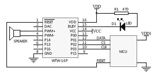
Three Line Mode=
I’ve taken the time to download sound clips, modify, and organize a few themes.
Games – sound effects for the mechanics and the animation, GLaDoS voices from the Portal video game
Spooky – selection of spooky sounds for Halloween projects.
LCARS – Star Trek computer phrases and sounds.
Zelda: Link To The Past – sounds from the video game.
Other themes online:
Star Wars Lightsaber sounds
Talking Clock
Alien Invasion Slot Machine uses the WT588D board for sound effects.
Parts:
Arduino Nano
Expansion Board
USB to mini USB ~ 5ft. cord
AC/DC Outlet Power Adapter
Project Box
WT588D Sound Module
8 x 7-segment Display module
(1-4) strips of 10 RGB 12mm LEDs.
(2) push-buttons
photocell
microphone
PIR sensor
Steps:
Prepare the following for wiring and connect to the expansion board:
WT588D with wiring harness and speaker
(1-4) strips of 10 RGB 12mm LEDs.
8 x 7-segment Display Module
(2) push-buttons
photocell
microphone
PIR sensor
Connect the push-buttons to the expansion board and upload test code.
Connect strips of 10 RGB 12mm LEDs to the expansion board and upload test code.
Connect the 8×7 segment display module to the expansion board and upload test code.
Connect the WT588D with wiring harness and speaker and upload test code.
Any sensor can be used to trigger specific or random sounds and going even further, a basic neural network could make decisions using multiple sensor inputs.
Connect the photocell to the expansion board and upload test code.
Connect the Microphone to the expansion board and upload test code.
Connect the PIR sensor to the expansion board and upload test code.

Completed SoundFXLight Project
Insert Arduino Nano into Expansion Board and plan to provide power using USB to mini USB cord. Optionally, AC/DC Outlet Power Adapter
Enclosing the project
Drill 7/16” – 1/2” holes into the project box:
HOLE 1: side
USB to mini USB ~ 5ft. cord
Optionally, AC/DC Outlet Power Adapter
HOLE 2: cover push-button
HOLE 3: cover push-button
top front side
HOLE 4: (1-4) strips of 10 RGB 12mm LEDs
HOLE 5: speaker connector
HOLE 6: side
microphone, PIR sensor
It takes time to learn how to use tools and equipment successfully, let alone, have the time to actually make the project meet your expectations. Time used for the project is time that could be spent with family, friends, learning something more important, etc.
You can purchase a completed SoundFXLight directly from me as a functioning example.

Arduino Pro-Mini directly connected to WT588D
Stay Tuned
Using Arduino to Make Motion Coming Soon!
Making Sound Effects with Arduino Sound and Voice Effects Sound plays an important role in the user experience by adding another layer of depth; making for a more realistic experience.
0 notes
Text
CrowPi 2 Is The Raspberry Pi Laptop and Electronics STEAM Workshop You’ve Dreamed Of
Our verdict of the CrowPi 2: Simply the best STEAM learning package we've seen yet. It's packed full of electronics sensors that are easy to start programming with in Scratch or Python. Jump on this one quick before the price goes up at retail (though even then, it'll be great value). 910
The Raspberry Pi is a fantastic development board, great for getting young minds into all manner of STEAM projects. But once you get to the electronics side of things, it can be a little fiddly to connect components. You’ll soon find yourself lost in a mass of wires and cabling.
The CrowPi 2 is an incredibly elegant solution that builds on the successes of the original. It isn’t just a Raspberry Pi laptop (though it is a pretty great one of those). Hidden underneath the keyboard is an extensive electronics workshop. It’s a self-contained all-in-one STEAM learning system. This is the Pi workshop everyone wishes they had.
It’s available on Kickstarter for the next few days, but be quick, as the price will go up after that.
What’s In The Box?
Inside the rather large CrowPi2 box, you’ll find:
The CrowPi 2 laptop consisting of case, electronics workshop board and integrated 11.6″ screen
Power supply
Raspberry Pi 4B 4GB
Two USB game controllers
Wireless Keyboard and Mouse, which require a dongle to be plugged in Power supply Getting started manual Printed Minecraft cubes on card stock
Additional electronic components (see later section)
That’s a lot of stuff.
Our test sample had the Raspberry Pi hardware pre-installed, but you may need to do that yourself given the procedure detailed in the Getting Started guide. It’s easy enough: a panel at the back slides off. Slot in the Pi, secure with some screws, then connect some cabling for power and screen.
To use the webcam, you’ll need to plug a short USB cable into one of the four external ports. Once the Pi is installed, the only clue is this tell-tale arrangement of ports.
Weighing 2.8 pounds (1.3kg) and measuring 11.4×7.5×1.8 inches (291x190x46mm), the laptop itself is a cheap-feeling plastic design. Without opening the clamshell, it looks like a netbook from 2005. This is in stark contrast to the metal-clad rugged toolbox design of the original CrowPi model. Realistically, it was likely a design decision to avoid the accusations that it’s a bomb. Which happened often with the original CrowPi. Because it did look like a bomb.
The keyboard too is a somewhat natty, thin plastic design. It’s functional and fits neatly inside the case, but the soft-touch keys feel as bad as expected. With a standby time of 120 hours and simple to recharge over micro-USB, at least you shouldn’t have to worry about the battery. I would have preferred something more solid, and wired–perhaps a coiled wire that would fit neatly back into the rear of the case.
Around the rear of the CrowPi 2 is a pull-out drawer. The manual references a battery that can slot in here, so I assume that’s an optional extra to come at a later date. There’s no mention of it on the Kickstarter though, so the idea may have just been shelved.
The Pi 4 that powers the system is hidden away at the back, only really visible through the fan on the mainboard. This is good as it saves space for even more pushbuttons, toggle switches, and flashy LED things on the front.
Your New Electronics Workshop
The beauty of the CrowPi is the integrated electronics workshop kit, built right into the case itself, underneath the keyboard.
Built-in components include:
LCD screen
8×8 RGB LED matrix display
4 digit LED segment display
Relay
Rocker style joystick
16 buttons (labeled as a calculator)
PIR sensor
Light sensor
Microphone
Vibration sensor
Ultrasonic distance sensor
Tilt sensor
Servo driver (Servo motor is separate)
Stepper driver (Stepper motor is separate)
Touch sensor
RFID reader/writer
Mini breadboard
GPIO breakout and state LEDs for each port
Then there’s a number of additional components that are supplied separately, and can be connected either through dedicated ports (such as the servo and stepper), or via the generic GPIO breakouts. You can also breadboard some of the components for small circuits. These bits consist of various motors, LEDs, a moisture sensor, resistors, RFID cards, and more.
CrowPi 2 Software
By default, the system launches in a customized version of Raspian. You’ll need to create an offline account before you can use it though. Thankfully the CrowPi 2 supports multiple offline accounts, which is great for school or family use.
The “Projects” button introduces you to most of the integrated electronics capabilities, though seemingly with no way to edit the code or find out more, it’s really just a hardware overview, which was a little off-putting to me. Natural curiosity will mean young minds want to start tinkering. It turns out you can learn and modify these basic programs, but need to do so from a different menu item.
The real meat of the package can be found under “Learning”, which consists of 32 guided Python tutorials for working with the on-board sensors and components, as well as 16 Scratch tutorials. As a novice Python programmer, I certainly found myself engaged by the lessons and seamless integration with the onboard hardware.
You’ll also find 12 speech recognition and AI face detection lessons, though these were a little harder to follow.
“Minecraft” launches the educational version of Minecraft along with a Python interpreter and a step-by-step guide book to programming using the Minecraft API.
“Game” whisks you away to a selection of somewhat boring Python games, curiously none of which can actually be played with the included gamepads. Nor is there the option to view or modify the code, which again seems like a lost opportunity.
“Microbit”, “Arduino”, and “Scratch” all launch you straight into the respective IDEs.
Overall, the interface could certainly use some refinement, at least the ability to launch a code editor for the included projects so you can begin modifying them off-the-bat. But taken as a whole, the amount of electronics programming learning material here is incredible and I can’t wait to get my 6-year-old onto this.
RetroPie
When you’re done learning, a version of RetroPie is included on a separate micro-SD card. It’s here where the gamepads can be used. Of course, there are no ROMs included, so you’ll need to use a USB stick and follow the RetroPie wiki to get some installed. The image included in our set was designed for the Raspberry Pi 3, but this was easily remedied by burning a fresh copy of the latest beta.
It’s also worth mentioning that other OSes are available. The CrowPi 2 is essentially just a Raspberry Pi 4B with a ton of extra sensors and built-in bits, so it should run any standard Raspberry Pi software. If you plan on using different OSes, you should buy additional SD cards and not overwrite the one that comes with the system, as it is heavily modified with the custom software and learning journey.
Is The CrowPi 2 Worth It?
Aside from the more “normal” laptop design, the CrowPi 2 is a big step up from the original, with potential for both home users and the educational sector alike. It blows away other competitors like the Piper in terms of sheer value. The Raspberry Pi 4 ensures a smooth desktop operation, and the customized software is a brilliant resource for learners from elementary school age and up.
Someone will inevitably comment that paying close to $300 for a glorified Raspberry Pi is mad–that you could buy the individual components of the CrowPi 2 for less than the overall selling price. At the Kickstarter pricing of $260, I’m not even sure that assertion is true–but moreover, it’s entirely missing the point. The CrowPi 2 is a complete Pi laptop and STEAM learning package. It’s neat, integrated, and includes an extensive learning journey. Nothing else on the market comes close to providing such an integrated course of study. There are certainly other Raspberry Pi laptop kits out there, but they’re not dissimilar in price and lack nearly all the additional sensors you’ll find here. And if $260 is too much, you can buy a basic kit for even cheaper without some of the added extras like additional components.
The CrowPi 2 isn’t aimed at the sort of person who just wants a screen and case for their Raspberry Pi. Nor is it aimed at the seasoned hardware programmer who’s putting together their latest smart home sensor array. They likely know exactly what components they need, and wouldn’t want a neatly packaged Pi laptop anyway. But for children or adults of all ages, there’s no better way to learn hardware, electronics, Python programming, and Scratch. The CrowPi 2 the best overall STEAM learning package we’ve seen yet.
Be quick though: the CrowPi 2 Kickstarter ends in a few days.
Enter the Competition!
CrowPi 2 Raspberry Pi Laptop Giveaway
Read the full article: CrowPi 2 Is The Raspberry Pi Laptop and Electronics STEAM Workshop You’ve Dreamed Of
CrowPi 2 Is The Raspberry Pi Laptop and Electronics STEAM Workshop You’ve Dreamed Of published first on http://droneseco.tumblr.com/
0 notes
Text
CrowPi 2 Is The Raspberry Pi Laptop and Electronics STEAM Workshop You’ve Dreamed Of
Our verdict of the CrowPi 2: Simply the best STEAM learning package we've seen yet. It's packed full of electronics sensors that are easy to start programming with in Scratch or Python. Jump on this one quick before the price goes up at retail (though even then, it'll be great value). 910
The Raspberry Pi is a fantastic development board, great for getting young minds into all manner of STEAM projects. But once you get to the electronics side of things, it can be a little fiddly to connect components. You’ll soon find yourself lost in a mass of wires and cabling.
The CrowPi 2 is an incredibly elegant solution that builds on the successes of the original. It isn’t just a Raspberry Pi laptop (though it is a pretty great one of those). Hidden underneath the keyboard is an extensive electronics workshop. It’s a self-contained all-in-one STEAM learning system. This is the Pi workshop everyone wishes they had.
It’s available on Kickstarter for the next few days, but be quick, as the price will go up after that.
What’s In The Box?
Inside the rather large CrowPi2 box, you’ll find:
The CrowPi 2 laptop consisting of case, electronics workshop board and integrated 11.6″ screen
Power supply
Raspberry Pi 4B 4GB
Two USB game controllers
Wireless Keyboard and Mouse, which require a dongle to be plugged in Power supply Getting started manual Printed Minecraft cubes on card stock
Additional electronic components (see later section)
That’s a lot of stuff.
Our test sample had the Raspberry Pi hardware pre-installed, but you may need to do that yourself given the procedure detailed in the Getting Started guide. It’s easy enough: a panel at the back slides off. Slot in the Pi, secure with some screws, then connect some cabling for power and screen.
To use the webcam, you’ll need to plug a short USB cable into one of the four external ports. Once the Pi is installed, the only clue is this tell-tale arrangement of ports.
Weighing 2.8 pounds (1.3kg) and measuring 11.4×7.5×1.8 inches (291x190x46mm), the laptop itself is a cheap-feeling plastic design. Without opening the clamshell, it looks like a netbook from 2005. This is in stark contrast to the metal-clad rugged toolbox design of the original CrowPi model. Realistically, it was likely a design decision to avoid the accusations that it’s a bomb. Which happened often with the original CrowPi. Because it did look like a bomb.
The keyboard too is a somewhat natty, thin plastic design. It’s functional and fits neatly inside the case, but the soft-touch keys feel as bad as expected. With a standby time of 120 hours and simple to recharge over micro-USB, at least you shouldn’t have to worry about the battery. I would have preferred something more solid, and wired–perhaps a coiled wire that would fit neatly back into the rear of the case.
Around the rear of the CrowPi 2 is a pull-out drawer. The manual references a battery that can slot in here, so I assume that’s an optional extra to come at a later date. There’s no mention of it on the Kickstarter though, so the idea may have just been shelved.
The Pi 4 that powers the system is hidden away at the back, only really visible through the fan on the mainboard. This is good as it saves space for even more pushbuttons, toggle switches, and flashy LED things on the front.
Your New Electronics Workshop
The beauty of the CrowPi is the integrated electronics workshop kit, built right into the case itself, underneath the keyboard.
Built-in components include:
LCD screen
8×8 RGB LED matrix display
4 digit LED segment display
Relay
Rocker style joystick
16 buttons (labeled as a calculator)
PIR sensor
Light sensor
Microphone
Vibration sensor
Ultrasonic distance sensor
Tilt sensor
Servo driver (Servo motor is separate)
Stepper driver (Stepper motor is separate)
Touch sensor
RFID reader/writer
Mini breadboard
GPIO breakout and state LEDs for each port
Then there’s a number of additional components that are supplied separately, and can be connected either through dedicated ports (such as the servo and stepper), or via the generic GPIO breakouts. You can also breadboard some of the components for small circuits. These bits consist of various motors, LEDs, a moisture sensor, resistors, RFID cards, and more.
CrowPi 2 Software
By default, the system launches in a customized version of Raspian. You’ll need to create an offline account before you can use it though. Thankfully the CrowPi 2 supports multiple offline accounts, which is great for school or family use.
The “Projects” button introduces you to most of the integrated electronics capabilities, though seemingly with no way to edit the code or find out more, it’s really just a hardware overview, which was a little off-putting to me. Natural curiosity will mean young minds want to start tinkering. It turns out you can learn and modify these basic programs, but need to do so from a different menu item.
The real meat of the package can be found under “Learning”, which consists of 32 guided Python tutorials for working with the on-board sensors and components, as well as 16 Scratch tutorials. As a novice Python programmer, I certainly found myself engaged by the lessons and seamless integration with the onboard hardware.
You’ll also find 12 speech recognition and AI face detection lessons, though these were a little harder to follow.
“Minecraft” launches the educational version of Minecraft along with a Python interpreter and a step-by-step guide book to programming using the Minecraft API.
“Game” whisks you away to a selection of somewhat boring Python games, curiously none of which can actually be played with the included gamepads. Nor is there the option to view or modify the code, which again seems like a lost opportunity.
“Microbit”, “Arduino”, and “Scratch” all launch you straight into the respective IDEs.
Overall, the interface could certainly use some refinement, at least the ability to launch a code editor for the included projects so you can begin modifying them off-the-bat. But taken as a whole, the amount of electronics programming learning material here is incredible and I can’t wait to get my 6-year-old onto this.
RetroPie
When you’re done learning, a version of RetroPie is included on a separate micro-SD card. It’s here where the gamepads can be used. Of course, there are no ROMs included, so you’ll need to use a USB stick and follow the RetroPie wiki to get some installed. The image included in our set was designed for the Raspberry Pi 3, but this was easily remedied by burning a fresh copy of the latest beta.
It’s also worth mentioning that other OSes are available. The CrowPi 2 is essentially just a Raspberry Pi 4B with a ton of extra sensors and built-in bits, so it should run any standard Raspberry Pi software. If you plan on using different OSes, you should buy additional SD cards and not overwrite the one that comes with the system, as it is heavily modified with the custom software and learning journey.
Is The CrowPi 2 Worth It?
Aside from the more “normal” laptop design, the CrowPi 2 is a big step up from the original, with potential for both home users and the educational sector alike. It blows away other competitors like the Piper in terms of sheer value. The Raspberry Pi 4 ensures a smooth desktop operation, and the customized software is a brilliant resource for learners from elementary school age and up.
Someone will inevitably comment that paying close to $300 for a glorified Raspberry Pi is mad–that you could buy the individual components of the CrowPi 2 for less than the overall selling price. At the Kickstarter pricing of $260, I’m not even sure that assertion is true–but moreover, it’s entirely missing the point. The CrowPi 2 is a complete Pi laptop and STEAM learning package. It’s neat, integrated, and includes an extensive learning journey. Nothing else on the market comes close to providing such an integrated course of study. There are certainly other Raspberry Pi laptop kits out there, but they’re not dissimilar in price and lack nearly all the additional sensors you’ll find here. And if $260 is too much, you can buy a basic kit for even cheaper without some of the added extras like additional components.
The CrowPi 2 isn’t aimed at the sort of person who just wants a screen and case for their Raspberry Pi. Nor is it aimed at the seasoned hardware programmer who’s putting together their latest smart home sensor array. They likely know exactly what components they need, and wouldn’t want a neatly packaged Pi laptop anyway. But for children or adults of all ages, there’s no better way to learn hardware, electronics, Python programming, and Scratch. The CrowPi 2 the best overall STEAM learning package we’ve seen yet.
Be quick though: the CrowPi 2 Kickstarter ends in a few days.
Enter the Competition!
CrowPi 2 Raspberry Pi Laptop Giveaway
Read the full article: CrowPi 2 Is The Raspberry Pi Laptop and Electronics STEAM Workshop You’ve Dreamed Of
CrowPi 2 Is The Raspberry Pi Laptop and Electronics STEAM Workshop You’ve Dreamed Of posted first on grassroutespage.blogspot.com
0 notes
Text
ESP32-CAM PIR Intruder Alert with Photo Capture and Send Image to Telegram App
youtube
ESP32-CAM PIR Intruder Alert with Photo Capture and Send Image to Telegram App | ESP32 Cam Motion Alert | Send Image to Telegram | ESP32 CAM project | Face Detection | Smart home automation | Security system using Esp32 Cam | Smart Security camera Telegram & Line app| ESP32-Cam – QuickStart. ****************************************************************** If You Want To Purchase the Full Project or Software Code Mail Us: [email protected] Title Name Along With You-Tube Video Link Project Changes also Made according to Student Requirements http://svsembedded.com/ è https://www.svskits.in/ M1: +91 9491535690 è M2: +91 7842358459 ****************************************************************** 1. Automate ESP32 and NodeMCU using Telegram Chat App, 2. Build a Camera Alert Application With RaspberryPi 3 and iOS/Android Pushbullet app, 3. Camera VC0706 Arduino send Image to FTP over GPRS SIM800L, 4. CCTV Motion Detect Telegram Dengan ESP32 CAM, 5. Control Arduino, Camera TTL, Ultrasonic, Using IOT and Telegram, 6. Design, Implementation and Practical Evaluation, 7. DIY ESP32 Alarm System Leverages 433 MHz Sensors, 8. Door sensor - line notify, 9. ESP32 Cam - IP camera on the cheap, 10. ESP-32 CAM - Motion triggered image alerts to telegram bot, 11. esp32 cam based intruder alert on telegram, 12. ESP32 CAM Based Video Surveillance Robot Over WiFi | Ai-Thinker ESP32-CAM Arduino IDE, 13. ESP32- Cam Face Recognition and Video Streaming, 14. ESP32 CAM Getting Started | Face Detection, 15. ESP32 Cam Motion Alert Send Image to Telegram, 16. ESP-32 CAM motion triggered alerts on telegram, 17. ESP32 cam send captured images to AWS, 18. ESP32 Camera: face detection, 19. ESP32 Doorbell via Telegram | Elektor Magazine, 20. Esp32cam and PIRmotion sensor send pics to Line&Telegram|Google assistant and blynk by ESP32 cam, 21. ESP32-CAM Face Recognition for Home Automation – Robot, 22. ESP32-CAM How to enroll faces using images saved in SD card and recognize face automatically, 23. ESP32-CAM How to save a captured photo to Firebase, 24. ESP32-CAM Motion Sensor Security Camera with Notification using Blynk - DIY Home surveillance system, 25. ESP32-CAM PIR Motion Detector with Photo Capture, 26. ESP32-CAM PIR Motion Detector with Photo Capture (saves to microSD card), 27. ESP32-CAM PIR Motion Detector with Photo Capture | ESP32 CAM project, 28. ESP32-CAM Send a captured photo by using Gmail, 29. ESP32-CAM Send a captured photo to Telegram, 30. Esp32cam streaming globally, 31. ESP32-CAM Surveillance Camera (Home Assistant Compatible), 32. ESP32-CAM Take Photo and Save to MicroSD Card, 33. ESP32-CAM Telegram BOT Take Picture (TUTORIAL KAMERA TELEGRAM), 34. Esp32cam, sensor pir ,dan telegram ( Alarm anti maling berbasis kamera dan telegram), 35. ESPHome + ESP32 Cam en Home Assistant, 36. Gas Alert System with IoT and Telegram App Using ESP32, 37. home automation using telegram | esp8266, 38. How To Make ESP32-CAM Take Photo and Save to MicroSD Card, 39. How to send images in telegram without loosing quality|Send photos in telegram without compression, 40. How to send pictures via WhatsApp and Telegram without losing quality, 41. How to send Push Notifications from Raspberry Pi to Smart, 42. How to share photos from telegram, 43. Intruder Detection System Using PIR Sensor, 44. Make Smart Security PiCamera with Motion Detection + Email Notification, 45. Membuat Camera Monitoring dengan ESP32-CAM, 46. MOTION TRIGGERED IMAGE CAPTURE AND EMAIL, 47. Using The ESP32-CAM Board And PIR Sensor, 48. Motion triggered telegram alert with esp32 camera, 49. NODEMCU BLYNK APP VIDEO DOOR BELL WITH SMART PHONE, 50. nodeMCU V2 +Line Notify+PIR motion sensor + VS1838 IR Receiver, 51. OpenCV Python Neural Network Autonomous RC Car, 52. PIR sensor with LED, buzzer and Picamera + Pushbullet Notification, 53. Project CCTV NodeMCU dan VC0706, 54. Running a Telegram Photo Bot on the ESP32-CAM – Robot, 55. Servo and camera detection with telegram bot, 56. Smart Wi-Fi Video Doorbell using ESP32 and Camera, 57. TELEGRAM - ESP32CAM - How to use ESP32Cam to Take Pictures with Telegram App, 58. Telegram Bot Tutorial 02 - Send photo video | Share location contact, 59. Turn your Smartphone into a Motion Sensor activated Security Camera System | DIY Projects, 60. Use python to read ESP32-CAM,
0 notes
Text
Fire Alarm with Siren and Water Sprinkler System Using Arduino
youtube
FIRE ALARM SYSTEM WITH SIREN AND WATER SPRINKLER ****************************************************************** If You Want To Purchase the Full Project or Software Code Mail Us: [email protected] Title Name Along With You-Tube Video Link Project Changes also Made according to Student Requirements http://svsembedded.com/ https://www.svskits.in/ M1: +91 9491535690 M2: +91 7842358459 ****************************************************************** 1. Intelligent Fire Detection & Automatic Water Sprinklers, 2. GSM based Automatic Fire Detection and Water Sprinkler, 3. intelligent fire detector with automatic water sprinkler system, 4. Heat switch (old tube light stater bulb) fire alarm system, 5. Arduino Security and Alarm System Project, 6. Firefighter System Without Using Arduino | Fire Fighting Robot DIY (Simple), 7. Arduino with Fire Sensor, LED and Buzzer (Tutorial), 8. GSM Based Security Alarm System using Arduino, 9. How to make a Automatic Door Opening system using IR sensor, 10. Advanced Home Security System using Arduino and GSM Module, 11. Fire Detection and Water Sprinkler Robot using Arduino, 12. NodeMcu ESP8266 Blynk Fire Alarm Security Notification, 13. Fire Alarm Using Arduino, 14. IOT PROJECTS: Arduino Home Security System, 15. Smoke Level Detector with Alarm using Arduino & MQ-2/MQ-5/MQ-135 Sensor, 16. Arduino Flame Sensor | Fire Detector, 17. Smoke Detector Alarm Without Using Arduino || MQ-6 Sensor, 18. How To - Smoke Alarm Monitoring with Arduino and MySensors, 19. Arduino-based Burglar and Fire Alarm System, 20. Password Based Door Lock Security System Using Arduino, 21. How to Make Fire Alarm Using Flame Sensor with Arduino, 22. Fire Security System Using GSM Module ,flame sensor and Arduino, 23. Home security with Arduino - Arduino Fire Alarm System, 24. Gas Detecting Alarm system with Arduino, 25. Automatic Railway Track Crack Detection System Using GSM & GPS, 26. Smoke alarm using Arduino uno and smoke sensor mQ2, 27. Musical Fire Alarm Hack - Super Mario Bros – Arduino, 28. How to make a fire alarm using battery 9v simply, 29. Density Based Traffic Signal Control System Using Arduino and IR Sensor, 30. GSM Sim800l Based Home Security System Using Arduino and Pir Sensor, 31. Arduino Fire Alarm (Flame sensor and Speaker), 32. Fire Alarm using Arduino uno and Flame Sensor; Arduino security system,DIY, 33. Fire/flame Detector using Flame Sensor and Arduino, 34. Make A Lazer Security System Using Arduino, 35. Zigbee Based Gas and Fire Detection System, 36. Mini Fire Alarm System using Arduino | Arduino with Fire Sensor,LED and Buzzer(Tutorial), 37. Fire Recognition & Extinguisher system using Image processing and Arduino, 38. GSM Based Security Alarm System using Arduino and 433Mhz Remote (V2 0), 39. Arduino Fire Alarm System - gsm security system using Arduino, 40. Learn about IoT based forest fire Alarm System, 41. Security System using Arduino Bluetooth Camera, 42. Home Security System using Arduino – Project, 43. Swachh Bharat Waste Collection Management System using IOT, 44. Forest fire Detection using Thingsspeak Prediction Algorithm –NodeMCU, 45. Home Security System Using RFID and Reed Switch Controlled using Arduino Micrcontroller, 46. Gas Leakage Alarm using Arduino with Matlab Simulink, 47. How to Make IOT Industry Protection System Using Arduino Project, 48. How To Make Smart Home Automation Using Arduino, 49. How to Make an Arduino Fire Flame Alarm, 50. Forest Fire Early Detection & Online Remote Monitoring Using Fire Sensor using Arduino,Raspberry Pi, 51. heat detector fire alarm system | alarm systems fire alarm using arduino nano and fire Sensor, 52. Remote Temperature | GAS | FIRE | LDR | PIR | Sensor's Monitoring on Internet with Arduino GPRS, 53. simple security system using Arduino - Arduino and Motion sensor, 54. Fire Alarm System using AVR Microcontroller, 55. Fire Alarm System using LabView and Arduino , 56. Simple fire alarm using arduino and labview
0 notes
Text
Zigbee Based Temperature Sensor, Smoke & Gas Sensor Alert Using ATmega328 | (LM35 + MQ2 + MQ6 +XBee)
youtube
Zigbee Based Temperature Sensor, Smoke & Gas Sensor Alert Using Arduino | (LM35 + MQ2 + MQ6) ****************************************************************** If You Want To Purchase the Full Project or Software Code Mail Us: [email protected] Title Name Along With You-Tube Video Link Project Changes also Made according to Student Requirements http://svsembedded.com/ https://www.svskits.in/ M1: +91 9491535690 M2: +91 7842358459 ****************************************************************** 1. Gas Fire Detection System XBee Basics, 2. MQ 6 CNG LPG Sensor Working Pin Explanation Price & Projects, 3. LPG gas leak detector alarm By MQ-6, 4. Detector de Fuga de GAS - Humo - MQ6, 5. Smoke Detector Alarm Without Using Arduino || MQ-6 Sensor, 6. LPG Gas Leakage Alarm Using MQ6 Sensor, 7. Smoke & Gas Sensor for Electronics Projects- MQ2, 8. How to Connect MQ2 Gas Sensor To Arduino, 9. Arduino Tutorial (LM35 Temp Sensor), 10. LM35 Temperature Sensor with Arduino Uno, 11. Zigbee Based Gas and Fire Detection System, 12. How to Make Zigbee Based Wireless Home Security System, 13. Zigbee Based Wireless Health Monitoring Project, 14. Zigbee based gas fire detection system, 15. Zigbee Based Secure Wireless Communication Using AES Encryption Wireless Communication Project, 16. What is ZIGBEE And How It Works, 17. Zigbee based Industrial Data Acquisition And Monitoing, 18. FOREST FIRE DETECTION SYSTEM USING SENSOR NETWORKS SURGEINDIA SMART INDIA HACKATHON 2018, 19. What is Arduino - Arduino Projects? Arduino Vs Raspberry Pi, 20. Top 10 IoT(Internet Of Things) Projects Of All Time | 2018, 21. IOT, ZIGBEE Based PRISON-Break Monitoring & Auto Alert System using Blynk Mobile Application, 22. ZigBee IOT Gateway India Wireless Remote Monitoring Wireless Temperature sensors Tangent TechnoLabs, 23. WSN Based Real Time Air Pollution Monitoring System Using Zigbee and LabVIEW, 24. Zigbee Based Room Temperature Controller System, 25. ZigBee based forest fire detection and control system, 26. IOT Based Gas Leakage Detection System | ESP8266 (NodeMcu) with Gmail, 27. Touch screen and Zigbee based Restaurant ordering system, 28. Zigbee Based Secured Wireless Communication Using AES, 29. Zigbee Based Gas Detection, 30. Zigbee Based gas fire detection 2, 31. Industrial IoT : Web Based Remotely Monitoring Temperature | GAS | FIRE | LDR | PIR – SENSORS, 32. Zigbee Based Wireless Sensing Platform To Monitor Agricultural Environment, 33. ZigBee Based Wireless Sensor Network for Fire Alarm Monitoring in Naval Vessels, 34. Sonoff Zigbee temperature and humidity sensor, 35. Monitoring System Based on Zigbee Wireless Sensor Network Projects, 36. MQ 6 CNG LPG Sensor Working Pin Explanation Price & Projects, 37. Zigbee based UV-IR Flame Detection for Security Purpose, 38. Research of Fire Detecting System based on ZigBee Wireless Network, 39. Zigbee Wireless Robot with camera_part, 40. ZigBee Based Wireless Sensor Network, 41. Zigbee Network Home Automation System - BMES Project Ideas, 42. Sri Sairam Engineering College | IOT & ZIGBEE Based Irrigation and Cultivation System for Agri, 43. Zigbee Based Alerting System for Mine Workers, 44. Forest fire monitoring system based on GPRS and Zigbee wireless Sensor Network, 45. WIRELESS & PPG BASED HEALTHCARE MONITORING SYSTEM USING MSP430,ZIGBEE AND GSM SMARTPHONE, 46. smoke detector using 8051 microcontroller, 47. Zigbee Based Weather Station Monitoring System using Arduino, 48. Zigbee based intelligent Helmet for coal miners, 49. Child Saver Machine & Wireless Monitoring Of Child in Borehole Rescue Operation System, 50. Image Processing based Forest Fire Detection System with email alert using VB.NET & Arduino, 51. Mini Project: ZigBee based Wireless Temperature Sensor + Data Logger, 52. Zigbee Smart Home IR Motion Detector, 53. A Zigbee Based Animal Health Monitoring System, 54. X-Bee Based Wireless Temperature Monitoring & Control by KitsGuru.com, 55. Industrial Monitoring System using LabVIEW and GSM, 56. Gas sensing wireless Robot " Controlled by Zigbee XBEE joystick and android application, 57. Industrial Parameter Monitoring System Using CAN Bus, 58. DIGITAL WEATHER STATION WITH DATA STORAGE, 59. Remote Temperature | GAS | FIRE | LDR | PIR | Sensor's Monitoring on Internet with Arduino GPRS, 60. ARM LPC2148 based wireless temperature data logger, 61. Real Time Agriculture/Paddy Crop Field Monitoring System using ARM, 62. Zigbee Based gas fire detection, 63. Zigbee Based Home Automation_griet_ece, 64. Dolby Sound Music System Stop at School Zone & Hospitals Zone, 65. Set up Zigbee with Home Assistant - ZHA Integration guide, 66. VEHICLE SAFETY SECURITY USING MEMS,TEMP,ALCOHOL,SMOKE,OBSTACLE & THEFT DETECTION WITH ARM7,GSM,GPS, 67. An ARM7 LPC2148 Based Temperature Measurement System Using CAN Protocol Implementation,SHOW LESS
0 notes
Text
Zigbee Based Temperature, Smoke & Gas Sensor Using ATmega328 and GSM Module with SMS Alert
youtube
Zigbee Based Temperature, Smoke & Gas Sensor Using ATmega328 and GSM Module with SMS Alert | Zigbee Based Temperature Sensor, Smoke & Gas Sensor Alert Using Arduino | (LM35 + MQ2 + MQ6) ****************************************************************** If You Want To Purchase the Full Project or Software Code Mail Us: [email protected] Title Name Along With You-Tube Video Link Project Changes also Made according to Student Requirements http://svsembedded.com/ https://www.svskits.in/ M1: +91 9491535690 M2: +91 7842358459 ****************************************************************** 1. Gas Fire Detection System XBee Basics, 2. MQ 6 CNG LPG Sensor Working Pin Explanation Price & Projects, 3. LPG gas leak detector alarm By MQ-6, 4. Detector de Fuga de GAS - Humo - MQ6, 5. Smoke Detector Alarm Without Using Arduino || MQ-6 Sensor, 6. LPG Gas Leakage Alarm Using MQ6 Sensor, 7. Smoke & Gas Sensor for Electronics Projects- MQ2, 8. How to Connect MQ2 Gas Sensor To Arduino, 9. Arduino Tutorial (LM35 Temp Sensor), 10. LM35 Temperature Sensor with Arduino Uno, 11. Zigbee Based Gas and Fire Detection System, 12. How to Make Zigbee Based Wireless Home Security System, 13. Zigbee Based Wireless Health Monitoring Project, 14. Zigbee based gas fire detection system, 15. Zigbee Based Secure Wireless Communication Using AES Encryption Wireless Communication Project, 16. What is ZIGBEE And How It Works, 17. Zigbee based Industrial Data Acquisition And Monitoing, 18. FOREST FIRE DETECTION SYSTEM USING SENSOR NETWORKS SURGEINDIA SMART INDIA HACKATHON 2018, 19. What is Arduino - Arduino Projects? Arduino Vs Raspberry Pi, 20. Top 10 IoT(Internet Of Things) Projects Of All Time | 2018, 21. IOT, ZIGBEE Based PRISON-Break Monitoring & Auto Alert System using Blynk Mobile Application, 22. ZigBee IOT Gateway India Wireless Remote Monitoring Wireless Temperature sensors Tangent TechnoLabs, 23. WSN Based Real Time Air Pollution Monitoring System Using Zigbee and LabVIEW, 24. Zigbee Based Room Temperature Controller System, 25. ZigBee based forest fire detection and control system, 26. IOT Based Gas Leakage Detection System | ESP8266 (NodeMcu) with Gmail, 27. Touch screen and Zigbee based Restaurant ordering system, 28. Zigbee Based Secured Wireless Communication Using AES, 29. Zigbee Based Gas Detection, 30. Zigbee Based gas fire detection 2, 31. Industrial IoT : Web Based Remotely Monitoring Temperature | GAS | FIRE | LDR | PIR – SENSORS, 32. Zigbee Based Wireless Sensing Platform To Monitor Agricultural Environment, 33. ZigBee Based Wireless Sensor Network for Fire Alarm Monitoring in Naval Vessels, 34. Sonoff Zigbee temperature and humidity sensor, 35. Monitoring System Based on Zigbee Wireless Sensor Network Projects, 36. MQ 6 CNG LPG Sensor Working Pin Explanation Price & Projects, 37. Zigbee based UV-IR Flame Detection for Security Purpose, 38. Research of Fire Detecting System based on ZigBee Wireless Network, 39. Zigbee Wireless Robot with camera_part, 40. ZigBee Based Wireless Sensor Network, 41. Zigbee Network Home Automation System - BMES Project Ideas, 42. Sri Sairam Engineering College | IOT & ZIGBEE Based Irrigation and Cultivation System for Agri, 43. Zigbee Based Alerting System for Mine Workers, 44. Forest fire monitoring system based on GPRS and Zigbee wireless Sensor Network, 45. WIRELESS & PPG BASED HEALTHCARE MONITORING SYSTEM USING MSP430,ZIGBEE AND GSM SMARTPHONE, 46. smoke detector using 8051 microcontroller, 47. Zigbee Based Weather Station Monitoring System using Arduino, 48. Zigbee based intelligent Helmet for coal miners, 49. Child Saver Machine & Wireless Monitoring Of Child in Borehole Rescue Operation System, 50. Image Processing based Forest Fire Detection System with email alert using VB.NET & Arduino, 51. Mini Project: ZigBee based Wireless Temperature Sensor + Data Logger, 52. Zigbee Smart Home IR Motion Detector, 53. A Zigbee Based Animal Health Monitoring System, 54. X-Bee Based Wireless Temperature Monitoring & Control by KitsGuru.com, 55. Industrial Monitoring System using LabVIEW and GSM, 56. Gas sensing wireless Robot " Controlled by Zigbee XBEE joystick and android application, 57. Industrial Parameter Monitoring System Using CAN Bus, 58. DIGITAL WEATHER STATION WITH DATA STORAGE, 59. Remote Temperature | GAS | FIRE | LDR | PIR | Sensor's Monitoring on Internet with Arduino GPRS, 60. ARM LPC2148 based wireless temperature data logger, 61. Real Time Agriculture/Paddy Crop Field Monitoring System using ARM, 62. Zigbee Based gas fire detection, 63. Zigbee Based Home Automation_griet_ece, 64. Dolby Sound Music System Stop at School Zone & Hospitals Zone, 65. Set up Zigbee with Home Assistant - ZHA Integration guide, 66. VEHICLE SAFETY SECURITY USING MEMS,TEMP,ALCOHOL,SMOKE,OBSTACLE & THEFT DETECTION WITH ARM7,GSM,GPS,
0 notes
Video
youtube
PIR SENSOR TUTORIAL - WITH OR WITHOUT ARDUINO Just before creating my next projects tutorial, which will be using a PIR sensor, I thought I might create a separate tutorial explaining the working of a PIR sensor. By doing that I will be able to keep my other tutorial short and to the point. So, without wasting time let’s discuss what is a PIR sensor and how we can use it in our project.
Blog Post: https://diyfactory007.blogspot.com/2018/04/pir-sensor-tutorial-with-or-without.html
0 notes