#PulseIn
Explore tagged Tumblr posts
Visit Tumblr Blog
Explore Tumblr blogs with no restrictions, modern design and the best experience.
Last Seen Tumblr Blogs


Fun Fact
Mobile US users spent an average of 115.8 minutes on Tumblr app monthly.
Text
Spring Break – BreakCore Music Player
Final Project
For my final project in physical computing, I designed and built a digital musical instrument that I call the Spring Break – BreakCore Music Player. Drawing inspiration from the New Interfaces for Musical Expression (NIME) movement, this instrument transforms hand gestures into musical actions, allowing me to perform and manipulate breakcore-style audio using two ultrasonic distance sensors connected to an Arduino and mapped into Max MSP. It’s a controller, a performance tool, and a kind of interactive sculpture all in one—and it really made me feel like I was DJing a rave set with my hands.


The original concept came together as I experimented with the HC-SR04 distance sensors. I had initially planned to use motion sensors, but they proved too difficult to wire. After talking with someone more experienced, I pivoted to ultrasonic sensors since they offer similar spatial sensing but with more reliable outputs. Once I got one sensor working, I saw how smoothly it could translate distance into digital signals, so I added a second. This two-sensor setup let me build a kind of “on/off” control system, where each hand movement could start or stop specific layers of music.


The physical design of the instrument was simple but meaningful. I laser cut a small enclosure using MakerCase and acrylic in the Spelman Innovation Lab, and decorated it with a guitar-shaped design on the front panel to visually signal its purpose as a musical object. Inside the box, I mounted the Arduino and wired both sensors to a single breadboard—something I hadn’t done before, but it worked flawlessly on the first try. The sensors were positioned facing upward so I could hover my hands over them during the performance.


Left: Arduino Code for first sample, Right: Testing first sample
The Arduino code handled the distance calculations and serial output. Each sensor was triggered in the loop, calculating the distance in centimeters and printing both values as a single line of data. Here's the exact code I used:
const int trigPins[2] = {9, 11};
const int echoPins[2] = {10, 12};
float distances[2];
long duration;
void setup() {
Serial.begin(9600);
for (int i = 0; i < 2; i++) {
pinMode(trigPins[i], OUTPUT);
pinMode(echoPins[i], INPUT);
}
}
void loop() {
for (int i = 0; i < 2; i++) {
// Trigger pulse
digitalWrite(trigPins[i], LOW);
delayMicroseconds(2);
digitalWrite(trigPins[i], HIGH);
delayMicroseconds(10);
digitalWrite(trigPins[i], LOW);
// Read pulse
duration = pulseIn(echoPins[i], HIGH, 30000); // timeout safety
distances[i] = (duration * 0.0343) / 2;
// If no signal, set to 0
if (duration == 0) distances[i] = 0;
// Print to serial
Serial.print(distances[i]);
Serial.print(" ");
}
Serial.println(); // New line
delay(100);
}
In Max MSP, I created a patch that received the serial data from the Arduino, unpacked it, and used simple conditional logic to check whether the hand was within a certain threshold distance—specifically 20 centimeters. If so, it sent a bang that triggered a set of audio samples. Each sensor was mapped to a different set of three layered breakcore audio loops. Here’s the final version of the patch:

The left and right sides of the patch represent each of the sensors. When a hand is detected within range, it activates all three samples on that side, creating a stacked, textured sound. I didn’t map pitch or volume directly, but the threshold-based triggering gave me solid, real-time control over the performance. The layering of audio and the fast, cut-up loops created that signature breakcore energy I was going for.
When it came time to compose a piece, I built my sound palette from breakcore-inspired loops and samples I either made or found online. The genre naturally lends itself to this kind of chaotic, reactive interaction. Once I tested the first drum loop with my hand and saw it activate in sync with my movement, I knew exactly what direction to go. My final piece was more of an improvised jam session than a strict composition, but that made it feel alive—and I genuinely felt like I was DJing with air gestures.
This project wasn’t easy. Learning Max MSP from scratch was a major challenge. The interface is not beginner-friendly, and figuring out how to parse serial data, unpack values, and link it to audio playback took a lot of trial and error. I also ran into a brief issue where one of my sensors wasn’t showing up in the serial monitor, which I eventually solved by testing it in a separate sketch and reconnecting the wiring. Another challenge was figuring out how to keep the whole build compact—I’d used two breadboards in my midterm, but I managed to wire both sensors on one board for this project, which helped with space and structure.
If I had more time, I’d love to build on this project by introducing more nuanced sound control. Maybe mapping pitch to distance, adding a third sensor for tempo control, or even building a visual interface with responsive lights or projections. I can definitely imagine this evolving into a fully-fledged digital instrument or live performance tool.
More than anything, this project taught me that I can make music with my hands—literally. I now understand how to translate gesture into sound, how to route sensor data into an audio environment like Max MSP, and how to create systems that feel playful and expressive. I walked into this project nervous about how much I didn’t know, and I came out of it with a finished, functional instrument that let me perform a genre I love. That’s something I’ll carry with me well beyond this class.
S.O to the Spelman Innovation Lab, the IL staff and Professor Holmes- I couldn’t have don’t this without you!
xx
0 notes
Text
Make an Obstacle Avoiding Robot

Overview
This project is about obstacle avoiding robot in this robot it will calculate the distance from the obstacles and make it move forward, backward, right and left.
In this obstacle avoiding robot if the ultrasonic sensor senses any obstacle it will give input to the hobby generator and it will move accordingly. If the slide switch is OFF then the motor will not work.
Hardware required
Arduino Uno R3
Jumper Wires
L293D
Hobby generator
Slide Switch
Ultrasonic Sensor
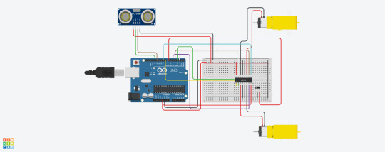
Fig 1. Circuit Diagram
Arduino Code : const int trigPin=13; const int echoPin=12; int enableA=8; const int motorPin1=3; const int motorPin2=5; int enableB=9; const int motorPin3=4; const int motorPin4=2; const int slideSwitch=7; int duration; int distance; void setup() { pinMode(enableA,OUTPUT); pinMode(enableB,OUTPUT); pinMode(motorPin1,OUTPUT); pinMode(motorPin2,OUTPUT); pinMode(motorPin3,OUTPUT); pinMode(motorPin4,OUTPUT); pinMode(trigPin,OUTPUT); pinMode(echoPin,INPUT); pinMode(slideSwitch,INPUT_PULLUP); analogWrite(enableA, 200); analogWrite(enableB, 200); Serial.begin(9600); } void loop() { if(digitalRead(slideSwitch) == LOW){ findDistance(); if(distance<=10){ //The robot will stop for a while rightMotor(0); leftMotor(0); delay(200); //The robot will move backward rightMotor(-255); leftMotor(-255); delay(300); //The robot will turn towards the right rightMotor(255); leftMotor(-255); delay(200); } else{ //The robot will move forwards rightMotor(255); leftMotor(255); } } //Since the Slide Switch is off, the robot will not move else{ rightMotor(0); leftMotor(0); } } void rightMotor(int speed) { analogWrite(enableB,speed); if(speed>0){ digitalWrite(motorPin3,HIGH); digitalWrite(motorPin4,LOW); } else if(speed<0){ digitalWrite(motorPin3,LOW); digitalWrite(motorPin4,HIGH); } else{ digitalWrite(motorPin3,LOW); digitalWrite(motorPin4,LOW); } } void leftMotor(int speed) { analogWrite(enableA,speed); if(speed>0){ digitalWrite(motorPin1,HIGH); digitalWrite(motorPin2,LOW); } else if(speed<0){ digitalWrite(motorPin1,LOW); digitalWrite(motorPin2,HIGH); } else{ digitalWrite(motorPin1,LOW); digitalWrite(motorPin2,LOW); } } void findDistance(){ digitalWrite(trigPin,LOW); delayMicroseconds(2); digitalWrite(trigPin,HIGH); delayMicroseconds(10); duration=pulseIn(echoPin,HIGH); distance=duration*0.0345/2; Serial.println(distance); }
Precautions
Connections should be done properly.
Arduino is case Sensitive so code accordingly.
Give different and appropriate colours to the wires.
Do you have questions regarding our STEM program?
Contact us anytime.
Take your first step into the magical world of coding for kids
0 notes
Text
CARRO AUTÔNOMO
// Definição dos pinos da ponte H L298N const int motor1A = 2; //Entrada 1 do motor 1 const int motor1B = 3; //Entrada 2 do motor 1 const int motor2A = 4; //Entrada 1 do motor 2 const int motor2B = 5; //Entrada 2 do motor 2
// Definiçao dos pinos do sensor ultrassonico const int trigPin = 6; const int echoPin = 7;
void setup() { //Define os pinos como saídas pinMode(motor1A, OUTPUT); pinMode(motor1B, OUTPUT); pinMode(motor2A, OUTPUT); pinMode(motor2B, OUTPUT);
pinMode(trigPin, OUTPUT); pinMode(echoPin, INPUT); }
void loop() { // digitalWrite(trigPin, LOW); delayMicroseconds(2); digitalWrite(trigPin, HIGH); delayMicroseconds(10); digitalWrite(trigPin, LOW);
// long duration = pulseIn(echoPin, HIGH); // //
float distance = (duration * 0.0343) / 2.0; // if (distance>10) { //Movimento para frente digitalWrite(motor1A, HIGH); digitalWrite(motor1B, LOW); digitalWrite(motor2A, HIGH); digitalWrite(motor2B, LOW);
} else { // digitalWrite(motor1A, LOW); digitalWrite(motor1B, LOW); digitalWrite(motor2A, LOW); digitalWrite(motor2B, LOW);
} }
0 notes
Text
Lighting Arduino Experiment 9 Music Visualizer Part 4
What was the experiment?
This was the final experiment in which if successful would result in the project being complete (prior to some cosmetic casing/modifications) the aim was to introduce a PING Ultrasonic sensor to change the colour of the LED’s based on the distance. This would mean that the final project would have three different forms of physical interaction - which would meet the aim to create a multi-interaction base light artifact.
How did I do it?
This experiment took a lot of research to understand the logic behind how ultrasonic sensors functioned, but luckily I had previous knowledge of ultrasonic devices due to personal hobbies, and thus I found the logic behind them a little easier than expected.
After doing my research into how these sensors work, via a digital output sending out an ultrasonic ping and then changing the pin-mode to digital input to receive a returning ultrasonic ping and measuring the distance based on the time between the output and input. (I will discuss in more detail the ‘Technical Information’ section) The next steps were a case of integrating this within my existing code, as I already had the PING Ultrasonic Sensor correctly connected as shown in part 1 of the ‘Music Visualizer’ set of experiments. To do so I had to take the logic of how the Ultrasonic sensors give and receive the ping, as discussed above, and integrate that using a combination of specific syntax for the sensor and mathematics to work out the distance based on the time between output and input - based on this distance I used that variable to change the colour of the LED’s using the R,G and B variables in which I previously set up for the exact reason of accessing with another component.
After I had this in working order I cut out the other three 6 Pixel LED strips from the main strip I purchased and attached those in the same way I did with the initial strip, putting me in a position where upon success the project would be complete in function and just require cosmetic neatening for presentation.
After the initial set up as described above and a lot of adjustment of the values of colours, this was the result.
vimeo
Every feature I planned for the final artifact was in full working order!
What issues did I face?
During this final part, the primary issues I faced came down to the values of both the numbers for both the mathematics and the colour values.
These issues consisted of me initially not using the correct conversion for microsecond to inches - but this was very noticeable and quickly corrected after researching it.
The second issue surrounding the colour values was just a case of trial and error; the result of the initial colour values being too high was that the lights were too bright for the camera to correctly pick up and needed to be lowered in order to capture it in a way I could present, due to this being a different level of light for each camera at different levels of exposure this took trial and error, testing different values and colours until I found what worked, the numerical values can be seen within my code below if you ware having a similar issue.
Technical Information
Below is the code used for the final project and a Circuit diagram made within Tinkercad, The circuit diagram is the same image as before for the same reason as stated in previous ‘Music Visualizer’ Parts, but in the case of this experiment the Digital button shown is actually a Digital Microphone in the real project.
#include <Adafruit_NeoPixel.h> int pot = A5; int val = 0; int test = 150; int sensorPin = 2; bool audio = 0; int R; int G; int B; int inchcoloR = 0; int inchcoloG = 0; int inchcoloB = 0; int ping = 4; int LEDPIN1 = 13; int LEDPIN2 = 12; int LEDPIN3 = 7; int LEDPIN4 = 6; int NUMPIXELS1 = 6; int NUMPIXELS2 = 6; int NUMPIXELS3 = 6; int NUMPIXELS4 = 6; Adafruit_NeoPixel pixels1 = Adafruit_NeoPixel(NUMPIXELS1, LEDPIN1); Adafruit_NeoPixel pixels2 = Adafruit_NeoPixel(NUMPIXELS2, LEDPIN2); Adafruit_NeoPixel pixels3 = Adafruit_NeoPixel(NUMPIXELS3, LEDPIN3); Adafruit_NeoPixel pixels4 = Adafruit_NeoPixel(NUMPIXELS4, LEDPIN4); void setup() { pinMode(sensorPin, INPUT); pixels1.begin(); pixels2.begin(); pixels3.begin(); pixels4.begin(); pixels1.show(); pixels2.show(); pixels3.show(); pixels4.show(); Serial.begin (9600); } void loop() { audio = digitalRead(sensorPin); long duration, inches; pinMode(ping, OUTPUT); digitalWrite(ping, LOW); delayMicroseconds(2); digitalWrite(ping, HIGH); delayMicroseconds(5); digitalWrite(ping, LOW); pinMode(ping, INPUT); duration = pulseIn(ping, HIGH); inches = microsecondsToInches(duration); val = analogRead(pot); Serial.print(inches); Serial.print("in, "); Serial.print(val); Serial.print("pot, "); Serial.println(); if (inches < 5) { inchcoloR = 0; inchcoloG = 0; inchcoloB = 15; } else if (inches < 10) { inchcoloR = 15; inchcoloG = 0; inchcoloB = 15; } else if (inches < 15) { inchcoloR = 15; inchcoloG = 0; inchcoloB = 0; } else if (inches < 20) { inchcoloR = 0; inchcoloG = 15; inchcoloB = 0; } else if (inches < 25) { inchcoloR = 0; inchcoloG = 15; inchcoloB = 15; } if (audio == HIGH) { R = inchcoloR; G = inchcoloG; B = inchcoloB; } if (audio == LOW) { R = 0; G = 0; B = 0; } if (val <= 0) { normal(); } else if(val >= 1020){ illuminate(6); } else if(val >= 820){ illuminate(5); } else if(val >= 615){ illuminate(4); } else if(val >= 410){ illuminate(3); } else if(val >= 205){ illuminate(2); } else if(val >= 100){ illuminate(1); } pixels1.show(); pixels2.show(); pixels3.show(); pixels4.show(); } long microsecondsToInches(long microseconds) { return microseconds / 74 / 2; } void normal(){ for(int i = 0; i < 6; i++){ pixels1.setPixelColor(i, pixels1.Color(0,0,0)); pixels2.setPixelColor(i, pixels2.Color(0,0,0)); pixels3.setPixelColor(i, pixels3.Color(0,0,0)); pixels4.setPixelColor(i, pixels4.Color(0,0,0)); } } void illuminate(int amount){ //reset all normal(); //then reilluminate for the amount of leds sent for(int i = 0; i < amount; i++){ pixels1.setPixelColor(i, pixels1.Color(R,G,B)); pixels2.setPixelColor(i, pixels2.Color(R,G,B)); pixels3.setPixelColor(i, pixels3.Color(R,G,B)); pixels4.setPixelColor(i, pixels4.Color(R,G,B)); } }

The primary technical point of this entry to discuss is the PING Ultrasonic sensor, i discussed above the base fundamentals of how this works - starting in pinMode OUTPUT, sending out a ping, waiting a small delay(to allow for a smooth transition) before turning to pinMode INPUT and receiving the ping. Although this is a digital in/output you can use ‘PulseIn’ to detect the duration between the ping being sent out and returned in microseconds, the next stage was to take this duration and work out how to turn this into inches, the mathematical formula for this is shown in the ‘long’ after the main loop, showing the formula in which was used to work out inches from the pulse duration.
From that point it was just a case of using the inches variable within an if/else statement to change the colours, I did not need to create another for loop based function for this as there was only a small amount of variations in colour and they affected every LED light in all strips, not just individuals.
The only other technical part of implementing the PING Ultrasonic sensor was ensuring the placement of the code did not affect the other components, and as such I decided to set it as the first thing to be calculated, and this did not cause any issues.
Components List
1x Arduino 1x Breadboard Varied Jumper Wires - depending on length and breadboard. 4x 6 Pixel Addressable WS2812b LED Strips 1x LM393 Digital Microphone 1x Potentiometer 1x PING Ultrasonic Sensor
Conclusion
This was the final experiment before I deemed the technical side of the project ‘complete’ and after correcting the issues mentioned in ‘issues faced’ everything was running smoothly to the quality in which I had aimed for when initially planning this project. I found the PING Ultrasonic Sensor extremely interesting to work with and will likely use it in future projects.
3 notes
·
View notes
Video
tumblr
Proyecto ultrasónico objetivo: la función de este proyecto es mendiante sensores controlar de forma remota la deforestación y la extinción de especies. estos sensores cumplen con la obligación de avisar y emiten un llamado contra la tala ilegal de arboles y cuidar el medio ambiente en el que vivimos.
Si estamos lejos, el sonido se emite con una frecuencia baja y se enciende el LED verde. Si estamos en una posición intermedia, el pitido aumenta la frecuencia y se encenderá el LED amarillo. Por último, si estamos demasiado cerca el pitido será muy agudo, una frecuencia alta, y se encenderá el LED rojo.
Para medir distancias con Arduino podemos hacerlo de diferentes maneras. Existen el sensor de infrarrojos, que utilizan las propiedades de la luz para calcular la distancia, y el sensor ultrasónico Arduino utiliza las propiedades de propagación del sonido para medir distancias. Más concreto utiliza los ultrasonidos. Este tipo de ondas sonoras se encuentran por encima del espectro audible por los seres humanos.

El funcionamiento es muy sencillo. El sensor envía una onda ultrasónica a través del disparador o trigger, revota contra el objeto y el receptor o echo detecta la onda. Sabiendo cuánto ha tardado en viajar dicha onda, podemos saber la distancia.

Para simular correctamente el sensor de distancia vamos a utilizar un buzzer Arduino. Estos componentes utilizan la piezoelectricidad, un fenómeno físico que afecta en determinados cristales (el cuarzo es el más común). Al someter un cristal de este tipo, se deforman y vibran. Si conseguimos que esa vibración tenga una frecuencia dentro del espectro audible, conseguiremos un sonido.

Por último, incorporamos el sistema de alerta visual para el sensor ultrasónico Arduino. Esto nos permite visualizar si estamos cerca o lejos de un obstáculo. Con 3 LEDs (verde, amarillo y rojo) conseguimos determinar si estamos lejos, cerca o en zona de peligro.
COMPONENTES:
Arduino UNO Protoboard donde conectaremos los componentes Cables para hacer las conexiones 3 resistencias de 220 Ω 1 LED verde 1 LED amarillo 1 LED rojo 1 sensor ultrasónico Arduino (HC-SR04) 1 buzzer
El sistema de aparcamiento consiste en detectar un objeto a través del sensor ultrasónico y avisar con señales de luz y sonido. Por lo tanto, ya tenemos la primera división, detectar el obstáculo y alertas con sonido y luces.
CODIGO ARDUINO ULTRASONICO
// Pines utilizados #define LEDVERDE 2 #define LEDAMARILLO 3 #define LEDROJO 4 #define TRIGGER 5 #define ECHO 6 #define BUZZER 9 // Constantes const float sonido = 34300.0; // Velocidad del sonido en cm/s const float umbral1 = 30.0; const float umbral2 = 20.0; const float umbral3 = 10.0; void setup() { // Iniciamos el monitor serie Serial.begin(9600); // Modo entrada/salida de los pines pinMode(LEDVERDE, OUTPUT); pinMode(LEDAMARILLO, OUTPUT); pinMode(LEDROJO, OUTPUT); pinMode(ECHO, INPUT); pinMode(TRIGGER, OUTPUT); pinMode(BUZZER, OUTPUT); // Apagamos todos los LEDs apagarLEDs(); } void loop() { // Preparamos el sensor de ultrasonidos iniciarTrigger(); // Obtenemos la distancia float distancia = calcularDistancia(); // Apagamos todos los LEDs apagarLEDs(); // Lanzamos alerta si estamos dentro del rango de peligro if (distancia < umbral1) { // Lanzamos alertas alertas(distancia); } } // Apaga todos los LEDs void apagarLEDs() { // Apagamos todos los LEDs digitalWrite(LEDVERDE, LOW); digitalWrite(LEDAMARILLO, LOW); digitalWrite(LEDROJO, LOW); } // Función que comprueba si hay que lanzar alguna alerta visual o sonora void alertas(float distancia) { if (distancia < umbral1 && distancia >= umbral2) { // Encendemos el LED verde digitalWrite(LEDVERDE, HIGH); tone(BUZZER, 2000, 200); } else if (distancia < umbral2 && distancia > umbral3) { // Encendemos el LED amarillo digitalWrite(LEDAMARILLO, HIGH); tone(BUZZER, 2500, 200); } else if (distancia <= umbral3) { // Encendemos el LED rojo digitalWrite(LEDROJO, HIGH); tone(BUZZER, 3000, 200); } } // Método que calcula la distancia a la que se encuentra un objeto. // Devuelve una variable tipo float que contiene la distancia float calcularDistancia() { // La función pulseIn obtiene el tiempo que tarda en cambiar entre estados, en este caso a HIGH unsigned long tiempo = pulseIn(ECHO, HIGH); // Obtenemos la distancia en cm, hay que convertir el tiempo en segudos ya que está en microsegundos // por eso se multiplica por 0.000001 float distancia = tiempo * 0.000001 * sonido / 2.0; Serial.print(distancia); Serial.print("cm"); Serial.println(); delay(500); return distancia; } // Método que inicia la secuencia del Trigger para comenzar a medir void iniciarTrigger() { // Ponemos el Triiger en estado bajo y esperamos 2 ms digitalWrite(TRIGGER, LOW); delayMicroseconds(2); // Ponemos el pin Trigger a estado alto y esperamos 10 ms digitalWrite(TRIGGER, HIGH); delayMicroseconds(10); // Comenzamos poniendo el pin Trigger en estado bajo digitalWrite(TRIGGER, LOW); }
1 note
·
View note
Video
tumblr
On this assignment I use a distant sensoron a NodeMCU and it record and show the distance via thinspeak.com.
Arduino Code:
//Jilbert_Bennett - Semester 2 Assignment 3 //NodeMCU Pin D1 - Trigger Pin D2 - Echo
#define TRIGGER 5 #define ECHO 4
#include <ESP8266WiFi.h> #include "ThingSpeak.h"
//WiFi Credentials char ssid[] = "***************"; //Censored the code for private reason char pass[] = "****************"; //Censored the code for private reason
WiFiClient client;
//ThingSpeak Credentials unsigned long myChannelNumber = 7*****4; //Censored the code for private reason char myWriteAPIKey[] = "F****************4"; //Censored the code for private reason
int wait = 5000;
void setup() {
Serial.begin(9600); WiFi.begin(ssid, pass); while(WiFi.status() != WL_CONNECTED){ delay(500); }
ThingSpeak.begin(client);
pinMode(TRIGGER, OUTPUT); pinMode(ECHO, INPUT); pinMode(BUILTIN_LED, OUTPUT);
}
void loop() {
long duration, distance; digitalWrite(TRIGGER, LOW); delayMicroseconds(2);
digitalWrite(TRIGGER, HIGH); delayMicroseconds(10);
digitalWrite(TRIGGER, LOW); duration = pulseIn(ECHO, HIGH); distance = (duration/2) / 29.1;
Serial.print("Centimeter:"); Serial.println(distance); delay(1000);
ThingSpeak.setField(1, distance);
ThingSpeak.writeFields(myChannelNumber, myWriteAPIKey);
delay(wait);
}
1 note
·
View note
Text
Videos a utilizar
Hablando sobre Arduino...
youtube
Para conectar el SRF05 se usara este video de referencia, donde muestra de una forma simple y compacta de conectarlo todo al Arduino Codigo a modificar: int triger = 3; int echo = 4; void setup() { pinMode(triger,OUTPUT); pinMode(echo,INPUT); Serial.begin(9600); } void loop() { digitalWrite(triger,LOW); delayMicroseconds(2); digitalWrite(triger,HIGH); delayMicroseconds(10); float tiempo=pulseIn(echo,HIGH); float distancia = (tiempo/2)/29.1; Serial.print(distancia); Serial.println("cm"); delay(500); }
0 notes
Text
How to interface an IR sensor with an Arduino?
Are you interested in learning about how to interface an IR sensor with an Arduino? In this post, we’ll go over the basics of what an IR sensor is, how it works, and how to connect it to an Arduino to create your own projects.
First, let’s talk about what an IR sensor is. IR stands for infrared, which is a type of electromagnetic radiation that is invisible to the human eye. An IR sensor is a device that detects this radiation and converts it into an electrical signal that can be processed by a microcontroller, like an Arduino.
There are different types of IR sensors available, but the most common one is the IR receiver module. This module has a photodiode that detects IR radiation and a preamplifier that amplifies the electrical signal produced by the photodiode. The output of the module is a digital signal that can be interpreted by the Arduino.

Now, let’s see how we can connect the IR receiver module to an Arduino. The module has three pins: VCC, GND, and OUT. VCC should be connected to the 5V pin on the Arduino, GND should be connected to the GND pin, and OUT should be connected to a digital input pin, like pin 2.
To read the signal from the module, we can use the Arduino’s built-in pulseIn() function. This function measures the duration of a pulse in microseconds and returns the value as an integer. We can use this value to determine the type of IR signal that was received.
For example, if we want to detect signals from a TV remote control, we can use the pulseIn() function to measure the duration of the pulse and compare it to the known values for each button on the remote. We can then use the Arduino to perform an action based on which button was pressed.
In conclusion, interfacing an IR sensor with an Arduino is a great way to create your own projects that can detect and respond to IR signals. With just a few components and some basic programming skills, you can create your own remote control, home automation system, or other cool projects. So why not give it a try and see what you can create?
Do check out the full article and Arduino code at IR sensor interfacing with Arduino
0 notes
Text
Automatic Door using Arduino

Understanding the Need for Automatic Doors
Imagine a world where opening a door is no longer challenging for those who can’t walk or see. Automatic doors address this need by offering a seamless solution. The core of this innovation is a door lock sensor that detects motion, allowing the door to open automatically. This project is not just a convenience; it’s a transformative tool for enhancing accessibility and independence.
How Do Automatic Doors Work?
The technology behind automatic doors is both fascinating and functional. At its heart is an ultrasonic sensor that detects motion and triggers the door to open. This system can be fine-tuned to respond to specific distances, ensuring it only opens when needed. The sensor is connected to an Arduino Uno R3, which processes the signal and activates a servo motor to open the door.
Hardware Required for Building an Automatic Door
To create your own automatic door, you will need:
Arduino Uno R3: The brain of the operation, processing signals, and controlling the motor.
Resistor: Ensures the proper flow of current.
Jumper Wires: Connect various components.
Ultrasonic Sensor: Detects the presence of a person.
Breadboard: A platform for assembling the circuit.
Servo Motor: Mechanically opens and closes the door.

Step-by-Step Guide to Building an Automatic Door
1. Setting Up the Hardware
Begin by assembling all the components on the breadboard. Connect the ultrasonic sensor to the Arduino Uno R3, ensuring that the connections are secure and correct. The servo motor should also be connected to the Arduino, ready to receive signals and actuate the door mechanism.
2. Writing the Arduino Code
The Arduino code is crucial for the operation of the automatic door. Below is a simple script to get you started:#include <Servo.h> Servo srv; #define maxdistance 100 void setup() { Serial.begin(9600); pinMode(13, OUTPUT); pinMode(12, INPUT); srv.attach(7); } void loop() { digitalWrite(13, LOW); delay(1000); digitalWrite(13, HIGH); delay(1000); digitalWrite(13, LOW); int d = pulseIn(12, HIGH); d = d / 29 / 2; Serial.println(d); if (d <= maxdistance) { srv.write(90); delay(1000); } else { delay(1000); srv.write(0); } }
3. Connecting Everything Together
Follow the schematic diagram to connect the hardware components properly. This ensures that the signals from the ultrasonic sensor are correctly processed by the Arduino, which in turn controls the servo motor.
4. Testing the Setup
Once everything is connected and the code is uploaded to the Arduino, test the setup by moving in front of the ultrasonic sensor. The door should open when motion is detected within the specified range.
Precautions When Building an Automatic Door
Building an automatic door is a straightforward project, but certain precautions must be taken to ensure success:
Proper Connections: Ensure all connections are secure and correct to avoid malfunctions.
Arduino Code Sensitivity: The code is case-sensitive, so be meticulous when typing it out.
Color-Coded Wires: Use different colors for the wires to identify connections easily.
Use Resistors: Protect sensors and components from damage by using appropriate resistors.
Benefits of Automatic Doors
Automatic doors are not just about convenience. They represent a significant improvement in accessibility for people with mobility or vision impairments. By eliminating the need to manually open doors, they provide a more inclusive environment.
Enhancing Independence
For individuals who find it challenging to open doors manually, automatic doors offer a level of independence that is both empowering and practical. This technology allows them to navigate spaces with ease, enhancing their overall quality of life.
Practical Applications
Automatic doors are commonly seen in commercial spaces, but their application extends to residential settings as well. Imagine a home where every door operates seamlessly, making daily life easier for everyone, especially those with disabilities.
Future of Automatic Doors
As technology advances, the future of automatic doors looks even more promising. Innovations in sensor technology and artificial intelligence could lead to doors that anticipate movements and preferences, offering even greater convenience and security.
Integration with Smart Home Systems
One exciting possibility is the integration of automatic doors with smart home systems. This would allow for seamless control of all doors in a home through a single interface, enhancing the smart living experience.
Energy Efficiency
Future designs may also focus on energy efficiency, ensuring that automatic doors contribute to sustainable living by minimizing energy consumption.
Conclusion
Automatic doors are more than just a technological novelty; they are a vital tool for creating inclusive and accessible environments. By understanding the hardware, software, and practical benefits, you can build a system that enhances the quality of life for those with mobility and vision impairments.
Do you have questions regarding our STEM program?
Contact us anytime.
Take your first step into the magical world of coding for kids
0 notes
Photo


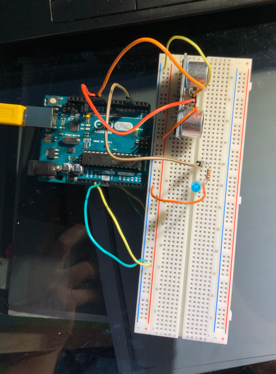


AL presionar LED queda prendido
Al presionar de nuevo LED queda apagado
int BOTON = 2;
int LED = 3;
int ESTADO = LOW;
void setup(){
pinMode (BOTON, INPUT); //2 conectado accionador (definición) como entrada
pinMode (LED, OUTPUT); //3 conectado a LED (to light) como salida
}
void loop(){
while (digitalRead(BOTON) == LOW) { //espero a que el boton se presione
}
ESTADO = digitalRead(LED); // leo el estado del LED
digitalWrite(LED, !ESTADO); // escribo valor contrario
while(digitalRead(BOTON) == HIGH) { // espera a que el botn deje de estar presionado antes de que el loop ejecute la primera linea - antirebote
}
}
Para que el LED quede encendido 5 seg.
int BOTON = 2;
int LED = 3;
int ESTADO = LOW;
void setup(){
pinMode (BOTON, INPUT); //2 conectado accionador (definición) como entrada
pinMode (LED, OUTPUT); //3 conectado a LED (to light) como salida
}
void loop(){
while (digitalRead(BOTON) == LOW) { //espero a que el boton se presione
}
digitalWrite(LED, HIGH); //enciende LED
delay(5000); //espera 5 seg.
digitalWrite(LED, LOW); //apaga LED
while(digitalRead(BOTON) == HIGH){ //Antirebote
}
}
PWM para cambio en brillo o intensidad con LED
int LED = 3;
int BRILLO;
void setup() {
pinMode(LED, OUTPUT);
}
void loop() {
for(BRILLO = 0; BRILLO < 256; BRILLO++) { //comienza LED apagado, por cada brillo menor a 256, ese brillo +1
analogWrite(LED, BRILLO); //affect the LED with the brillo
delay(15); // haz el +1 cada 15 mseg.
}
for(BRILLO = 255; BRILLO >=0; BRILLO--) { //comienza LED prendido con máximo brillo, por cada brillo mayor o igual a 256, ese brillo -1
analogWrite(LED, BRILLO);
delay(15);
}
PWM para cambio en brillo o intensidad con LED y potenciómetro
int LED = 3;
int BRILLO;
int POT = 0;
void setup() {
pinMode(LED, OUTPUT);
// las entradas analógicas no requieren incialización
}
void loop() {
BRILLO = analogRead(POT) / 4; //el 4 hace la división de las 1023 variables para que quepan en el rango de 5V
analogWrite(LED, BRILLO);
}
Sensor ultrasónico y LED
int TRIG = 10;
int ECO = 9;
int LED = 3;
int DURACION;
int DISTANCIA;
void setup () {
pinMode(ECO, INPUT); // pin que obtiene pulso
pinMode(TRIG, OUTPUT); // pin que dispara pulso
pinMode(LED, OUTPUT);
Serial.begin(9600); //para abrir monitor serial, arduino envía info a compu, 9600 tasa de velocidad de la comunicación
}
void loop () {
digitalWrite(TRIG, HIGH); //sale pulso
delay(1);
digitalWrite(TRIG, LOW);
DURACION = pulseIn (ECO, HIGH); //asignamos un valor de tiempo que tarda en llegar pulso a ECO a DURACION
DISTANCIA = DURACION / 58.2; //duración entre 58.2 (valor especificado por el sensor)
Serial.println(DISTANCIA); //colocará el valor de la distancia y dará enter automático
delay(200);
if(DISTANCIA <= 20 && DISTANCIA >=0) { //cuando la distancia sea menor que 20 y mayor o igual a 0 (rangos negativos significan fuera de rango)
digitalWrite(LED, HIGH); // LED ON
delay(DISTANCIA * 20); // el LED se prenderá y apagará con más rapidez cada vez que algo esté más cerca
digitalWrite(LED, LOW);
}
}
RAINBOW LED
int del=100;
void setup()
{
pinMode(2, OUTPUT);
pinMode(3, OUTPUT);
pinMode(4, OUTPUT);
pinMode(5, OUTPUT);
pinMode(6, OUTPUT);
pinMode(7, OUTPUT);
pinMode(8, OUTPUT);
pinMode(9, OUTPUT);
}
void loop() {
digitalWrite(2, HIGH);
delay(del);
digitalWrite(2, LOW);
digitalWrite(3, HIGH);
delay(del);
digitalWrite(3, LOW);
digitalWrite(4, HIGH);
delay(del);
digitalWrite(4, LOW);
digitalWrite(5, HIGH);
delay(del);
digitalWrite(5, LOW);
digitalWrite(6, HIGH);
delay(del);
digitalWrite(6, LOW);
digitalWrite(7, HIGH);
delay(del);
digitalWrite(7, LOW);
digitalWrite(8, HIGH);
delay(del);
digitalWrite(8, LOW);
digitalWrite(9, HIGH);
delay(100);
digitalWrite(9, LOW);
digitalWrite(8, HIGH);
delay(del);
digitalWrite(8, LOW);
digitalWrite(7, HIGH);
delay(del);
digitalWrite(7, LOW);
digitalWrite(6, HIGH);
delay(del);
digitalWrite(6, LOW);
digitalWrite(5, HIGH);
delay(del);
digitalWrite(5, LOW);
digitalWrite(4, HIGH);
delay(del);
digitalWrite(4, LOW);
digitalWrite(3, HIGH);
delay(del);
digitalWrite(3, LOW);
}
1st disfunctional try for the Heart Rate Plotter
/* PulseSensor Starter Project and Signal Tester
* The Best Way to Get Started With, or See the Raw Signal of, your PulseSensor.com™ & Arduino.
*
* Here is a link to the tutorial
* https://pulsesensor.com/pages/code-and-guide
*
* WATCH ME (Tutorial Video):
* https://www.youtube.com/watch?v=RbB8NSRa5X4
*
*
-------------------------------------------------------------
1) This shows a live human Heartbeat Pulse.
2) Live visualization in Arduino's Cool "Serial Plotter".
3) Blink an LED on each Heartbeat.
4) This is the direct Pulse Sensor's Signal.
5) A great first-step in troubleshooting your circuit and connections.
6) "Human-readable" code that is newbie friendly."
*/
// Variables
int PulseSensorPurplePin = 0; // Pulse Sensor PURPLE WIRE connected to ANALOG PIN 0
int LED13 = 13; // The on-board Arduion LED
int Signal; // holds the incoming raw data. Signal value can range from 0-1024
int Threshold = 550; // Determine which Signal to "count as a beat", and which to ingore.
// The SetUp Function:
void setup() {
pinMode(LED13,OUTPUT); // pin that will blink to your heartbeat!
Serial.begin(9600); // Set's up Serial Communication at certain speed.
}
// The Main Loop Function
void loop() {
Signal = analogRead(PulseSensorPurplePin); // Read the PulseSensor's value.
// Assign this value to the "Signal" variable.
Serial.println(Signal); // Send the Signal value to Serial Plotter.
if(Signal > Threshold){ // If the signal is above "550", then "turn-on" Arduino's on-Board LED.
digitalWrite(LED13,HIGH);
} else {
digitalWrite(LED13,LOW); // Else, the sigal must be below "550", so "turn-off" this LED.
}
delay(10);
}
0 notes
Text
Arduino: Halloween Kürbis Projekt

Passend zur Halloween-Zeit, möchte ich ein Projekt mit dem Arduino und einem gedruckten Halloween Kürbis präsentieren.

Arduino: Halloween Kürbis Projekt Den Kopf habe ich mit transparentem Filament gedruckt. Da ich ultra, helle LEDs verwenden möchte, schleife ich diesen etwas an, so dass es später etwas diffuser wirkt.
benötigte Bauteile
Für dieses Projekt werden einige Bauteile benötigt, welche ich nachfolgend auflisten möchte: elektronische Bauteile - 1x Arduino Nano V3.0, - 1x Breadbord, 170 Pin, - 1x Ultraschallsensor HC-SR04, - 1x LED, 5 mm, ultra Hell, - 1x ISD1820 Bausatz, - 1x 220 Ohm Widerstand, - 1x Schalter, - 1x Batteriefach (zbsp. für 4x AAA Batterien), - 1x 9g Servo, - 14x Breadboardkabel, 20 cm, männlich - weiblich Zusätzlich wird noch ein Gehäuse benötigt und natürlich der Kürbiskopf. Ich habe diese Vorlage von Thingiverse.com heruntergeladen und gedruckt.
Werkzeuge
Um das Projekt aufzubauen, habe ich folgende Werkzeuge verwendet: - Bohrmaschine (vorzugsweise Akkubohrer), - diverse Holzbohrer - 15 mm, - 12 mm, - 10 mm - 5 mm - Laubsäge - Lötkolben - hitzebeständige Unterlage - Lötfett, - Lötzinn
Aufbau & Schaltung
Der gesamte Aufbau soll später in ein kleines Gehäuse passen, daher sieht es etwas nach Spagetti aus, wenn man den Deckel öffnet :)


Schaltung

Schaltung - Halloween Kürbiskopf
Programmierung
#include int servomotor = 5; int sound = 4; int led = 2; int trigger = 7; int echo = 6; Servo servo; int position = 0; const int waitTime = 15; const int PAUSE = 5000; long lastActionTime = -1; void setup() { Serial.begin(9600); pinMode(servomotor, OUTPUT); pinMode(sound, OUTPUT); pinMode(led, OUTPUT); pinMode(trigger, OUTPUT); pinMode(echo, INPUT); servo.attach(servomotor); } void loop() { int lengthEcho = readEcho(); long currentMillis = millis(); if (lastActionTime < (currentMillis - PAUSE)) { lastActionTime = currentMillis; Serial.println(lengthEcho); if (lengthEcho < 60) { Serial.println("loop"); digitalWrite(sound, HIGH); delay(500); digitalWrite(sound, LOW); movePumpkin(); } } } int readEcho(){ digitalWrite(trigger, LOW); delayMicroseconds(2); digitalWrite(trigger, HIGH); delayMicroseconds(10); digitalWrite(trigger, LOW); int cm = pulseIn(echo, HIGH) / 58.0; return (int(cm * 100.0)) / 100.0; } void movePumpkin() { boolean ledActive = false; Serial.println("moveP"); for (position = 0; position < 90; position++) { servo.write(position); ledActive = !ledActive; digitalWrite(led, ledActive?HIGH:LOW); delay(waitTime); } for (position = 90; position >= 1; position--) { servo.write(position); ledActive = !ledActive; digitalWrite(led, ledActive?HIGH:LOW); delay(waitTime); } lastActionTime = millis(); }
Video
Read the full article
#Arduino#ArduinoNano#ArduinoProjekt#Halloween#ISD1820#Kürbiskopf#LED#Leuchtdiode#Servomotor#Ultraschallsensor
1 note
·
View note
Text
Project 2
I had some trouble coming up with an idea for this project, but eventually decided on combining the ultrasonic sensor and servo motor. I ended up creating a small experience centered around the idea of balance.
An ultrasonic sensor measures how far a person is. By moving away and towards the sensor a servo motor moves and arm back and forth. The goal is to balance a coin on the arm by just moving the arm with your body. In this way I tried to encompass the feeling of balancing something with your own body except the experience is now external. You no longer have direct control and have to try and use the arduino instead.
I figured the idea of balance was universal. Taking the idea a step further as a student you are trying to balance many things in your life, so my goal was to create a small reflection of that physically.
I had a few issues while working on this project. I see myself as more straightforward so creating a poetic experience did not come to me easily. I bounced around with a lot of different ideas, before landing on what I have now. I think in the end it does a good job of creating a poetic experience.
When building the system I had some issues with the ultrasonic sensor. For some reason I was not getting any input and ended up taking it apart multiple times trying to find the issue. Eventually I realized I was using the wrong resistor. After changing it out I was finally able to get a reading.
I also experimented with adding a capacitive sensor where the coin rests. My idea was to start and stop the experience if the coin is not on the arm. I tried using foil and some resistors to measure if the coin was placed on the arm, but I could never get the reading to be very accurate. The sensor would either think the coin is always there or never there and sometimes my hand or something else would trigger it. My final solution was to just slow the movement to make it easier to just place the coin. The variations in the ultrasonic sensor make the experience challenging enough still with the slower movement.
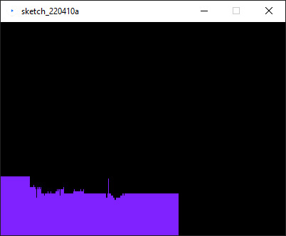
I also hooked my ultrasonic sensor up to processing to map the movement. This was probably the most challenging part. I went through multiple different projects to try and read arduino input on my PC. I finally landed on Processing as it worked right out the box and I was able to graph the users distance.
Video link: https://youtu.be/vOSW7lRcbXY


Arudino Code:
include
define echoPin 2
define trigPin 3
long duration; int distance; int pos = 0; Servo myservo; bool pause = true;
void setup() { pinMode(trigPin, OUTPUT); pinMode(echoPin, INPUT); Serial.begin(9600); myservo.attach(9); } void loop() { digitalWrite(trigPin, LOW); delayMicroseconds(2); digitalWrite(trigPin, HIGH); delayMicroseconds(10); digitalWrite(trigPin, LOW); duration = pulseIn(echoPin, HIGH); distance = duration * 0.034 / 2; //Serial.print("Distance: "); Serial.println(distance); if (distance > 18) { myservo.write(95); delay(1); } else if (distance < 5){ myservo.write(88); delay(1); } else { myservo.write(93); delay(10); }
}
Processing Code:
import processing.serial.*;
Serial myPort; // Create object from Serial class String val; // Data received from the serial port int xPos = 1; float inByte = 0; float prevInByte = 0;
void setup() { size(400, 300); String portName = Serial.list()[0]; myPort = new Serial(this, portName, 9600); background(0); }
void draw() { if ( myPort.available() > 0) { val = myPort.readStringUntil('\n'); if (val != null) { val = trim(val); inByte = float(val); println(inByte); inByte = map(inByte, 0, 1023, 0, height); } if(inByte < 100){ stroke(127, 34, 255); line(xPos, height, xPos, height - inByte * 10); prevInByte = inByte; } else { stroke(127, 34, 255); line(xPos, height, xPos, height - prevInByte * 10); }if (xPos >= width) { xPos = 0; background(0); } else { xPos++; }
} }
Sources: https://docs.arduino.cc/built-in-examples/communication/Graph
https://learn.sparkfun.com/tutorials/connecting-arduino-to-processing/all#introduction
0 notes
Text
P1 Blink/lightshow
This project has the user put their hand out in front to make the distance measurer to make the lights light up in different ways. If you flip the switch you are able to play a game to find a certain combination that make the lights dance. This piece was decently easy to make following the slides on mycourses. The hardest part of it was remembering how to set up a switch.


const int ledPin1 = 16; const int ledPin2 = 17; const int ledPin3 = 18; const int ledPin4 = 19; const int ledPin5 = 20; const int ledPin6 = 21;
int randomNum = 0;
const int trigPin = 3; const int echoPin = 2;
const int buttonPin = 5; int buttonState = 0;
volatile boolean sonarOn = false;
unsigned long oldDist = 0;
void setup() { // put your setup code here, to run once: pinMode(ledPin1, OUTPUT); pinMode(ledPin2, OUTPUT); pinMode(ledPin3, OUTPUT); pinMode(ledPin4, OUTPUT); pinMode(ledPin5, OUTPUT); pinMode(ledPin6, OUTPUT);
pinMode(trigPin, OUTPUT); pinMode(echoPin, INPUT);
pinMode(buttonPin, INPUT);
randomNum = random(100,800); }
void loop() { // put your main code here, to run repeatedly: oldDist = getSonar(); Serial.print(oldDist); buttonState = digitalRead(buttonPin); if(buttonState == HIGH){ if((randomNum + 200) > oldDist > (randomNum - 200)) { digitalWrite(ledPin3,LOW); digitalWrite(ledPin4,LOW); digitalWrite(ledPin1,LOW); digitalWrite(ledPin6,LOW); digitalWrite(ledPin2,LOW); digitalWrite(ledPin5,LOW); delay(100); digitalWrite(ledPin1,HIGH); delay(100); digitalWrite(ledPin2,HIGH); delay(100); digitalWrite(ledPin3,HIGH); delay(100); digitalWrite(ledPin4,HIGH); delay(100); digitalWrite(ledPin5,HIGH); delay(100); digitalWrite(ledPin6,HIGH); delay(100); } else { digitalWrite(ledPin3,HIGH); digitalWrite(ledPin4,HIGH); digitalWrite(ledPin1,HIGH); digitalWrite(ledPin6,HIGH); digitalWrite(ledPin2,HIGH); digitalWrite(ledPin5,HIGH); } } else{ if(oldDist > 750) { digitalWrite(ledPin1,LOW); digitalWrite(ledPin6,LOW); digitalWrite(ledPin2,LOW); digitalWrite(ledPin5,LOW); } if(oldDist < 750) { digitalWrite(ledPin1,HIGH); digitalWrite(ledPin6,HIGH); digitalWrite(ledPin2,LOW); digitalWrite(ledPin5,LOW); } if(oldDist < 500) { digitalWrite(ledPin2,HIGH); digitalWrite(ledPin5,HIGH); digitalWrite(ledPin3,LOW); digitalWrite(ledPin4,LOW); } if(oldDist < 250) { digitalWrite(ledPin3,HIGH); digitalWrite(ledPin4,HIGH); } }
}
/** updateSonarOn: called only if switch state changes * via interrupt. Update sonarOn based on switch value */ /**void updateSonarOn() { sonarOn = digitalRead(switchPin) == HIGH; }*/
/** getSonar: read sonar sensor and return echo duration * @return {unsigned long} duration of sonar pulse */ unsigned long getSonar() { /* if (debug) { digitalWrite(debugLed, HIGH); }*/ // Clears the trigPin digitalWrite(trigPin, LOW); delayMicroseconds(2);
//Read sonar value without getting interrupted noInterrupts();
// Sets the trigPin on HIGH state for 10 micro seconds digitalWrite(trigPin, HIGH); delayMicroseconds(10); digitalWrite(trigPin, LOW); // Reads the echoPin, returns the sound wave travel time in microseconds unsigned long duration = pulseIn(echoPin, HIGH);
interrupts(); //okay to interrupt now
// Calculating the distance in cm /*if (debug) { digitalWrite(debugLed, LOW); }*/ return duration; }
0 notes
Text


Final Project: Sensor Controlled Pet Feeder
List of components used:
UNO R3 Controller Board
Power Supply Module
Servo Motor SG60
Ultrasonic Sensor
830 Tie-Points Breadboard
9V Battery / 9V1A Adapter
Female-to-Male Dupont Wire (x5)
Jumper Wire (x2)
Technical Description:
When considering what I should create for my final artefact for this module, I struggled narrowing down what I could do within this immense world of physical computing. Eventually, I decided to build upon the small experiments I have completed and combine the skills and knowledge that I have learnt throughout this module with something that I am passionate about. I wanted to incorporate my love for animals and my pets into my project, so I decided to create a sensor controlled pet feeder.
Obviously this is not the first time that such a thing has been created so my idea is not relatively groundbreaking but that was never my intention. I found many examples on YouTube of people who have created similar artefacts and have included in my references those that have influenced my project the most.
Initially I had planned to create the pet feeder for my dog, Kiara, however after much trial and error I soon realised that the feeder itself was too small and the food for my dog was too heavy for the artefact to be used to its full potential. Video evidence of my dog with the automatic pet feeder can be found in the google drive link below. So I set my sights on something smaller and decided to try the automatic pet feeder with my two rabbits; Snowdrop and Bluebell. As you can see from the video provided in this post the artefact was more successful. When experimenting the feeder with my dog I learnt that the cardboard pathway that released the food was too flimsy along with the handle on the servo motor. I decided to make adjustments before trying with my rabbits and made a more reliable pathway out of stronger cardboard and used a small wooden stick instead of cardboard for the handle.
As for the wiring and more technical aspects of the automatic feeder I adapted the initial tutorial that I had found on YouTube. I came to the conclusion that I needed to wire a power supply module on the breadboard to provide power to the servo motor as well as the motion sensor simultaneously. Initially, I used the 9V battery provided within the kit but after much use it slowed the servo motor down until it stopped working completely. I changed the power source to the 9V1A adapter which solved the issue however did limit the portability of the feeder itself.
Whilst using the feeder I soon realised that it is essentially useless when the food is not lying above the servo motor handle as instead of falling into the pathway it is simply swept aside inside the box. I also had to have a small gap cut into the food compartment to fit the breadboard and power supply module, this could have been improved by using a larger cardboard box for the feeder.
Overrall, I am pleased with the outcome of my artefact. I enjoyed wiring the components together to create something useful and interesting. Although there is much improvement that could be done, essentially it did work and released food for my rabbits. As for how I would improve the feeder if I were to come back to this project; I would most certainly use a larger cardboard box and a bigger battery for ease of use and placement.
Relevant links:
https://letsmakeprojects.com/arduino-automatic-pet-feeder/
https://letsmakeprojects.com/how-to-make-arduino-toll-tax-barrier/
https://www.youtube.com/watch?v=zQ8SjIcYC5w&ab_channel=jeevanjee
Code:
#include <Servo.h> //servo library
Servo servo;
int trigPin = 2;
int echoPin = 3;
int servoPin = 9; //pin choice is yours
long duration, dist, average;
long aver[3]; //array for average
void setup() {
servo.attach(servoPin);
pinMode(trigPin, OUTPUT);
pinMode(echoPin, INPUT);
servo.write(0); //close cap on power on
delay(1000);
servo.detach();
}
void measure() {
digitalWrite(trigPin, LOW);
delayMicroseconds(5);
digitalWrite(trigPin, HIGH);
delayMicroseconds(15);
digitalWrite(trigPin, LOW);
pinMode(echoPin, INPUT);
duration = pulseIn(echoPin, HIGH);
dist = (duration/2) / 29.1; //obtain distance
}
void loop() {
for (int i=0;i<=2;i++) { //average distance
measure();
aver[i]=dist;
delay(50); //delay between measurements
}
dist=(aver[0]+aver[1
]+aver[2])/3; //average distance by 3 measurements
if ( dist<15 ) {
//if hand on the distance 10...15 cm
servo.attach(servoPin);
delay(1);
servo.write(150);
delay(3000); //wait 5 seconds or u can change this value
servo.write(0);
delay(1000);
servo.detach();
}
}
0 notes
Text
Final Project
Google Drive link:
https://drive.google.com/drive/folders/1zSZ-e4LBA1PKyKbaP7zTlJ65zkoJpR1G?usp=sharing
My final Project was a culmination of 3 main stages and with a bonus of the 4th stage if it could be done.
1st stage: Ultrasonic Sensor and Buzzer
2nd stage: Addition of the RFID Reader
3rd stage: Addition of a button (Completed but didnt work)
4th stage: Show time left on a display (not completed)
Additional parts needed:
Ultrasonic sensor, buzzer and RFID
Eleven Male to Female wires (seven to RFID, four to Ultrasonic)
Two Male to Male wires
100 Ohm Resistor
Button
Button
Five Male to Male wires
10k Ohm resistor
How I went about creating it:
I started off with the base of the Ultrasonic Sensor and buzzer setup:

I was happy with this as stage one and was excited to increase its complexity further.
I then added a RFID reader to allow for the user to pause the intruder detection for a certain amount of time allowing them to enter and leave without the buzzer going off.

This was my initial idea now complete but I wanted more, I wanted to simulate that the RFID was the entrance pass and to not be used as the Exit too. Therefore I added a button to be an overide from the inside and allow the user to leave without the buzzer going off.

I ran into some problems with the button as I couldnt figure out which direction it needed to face and after trying to fix the issue it made problems with the rest of the arduino. The code I had written also didnt work with my new addition and meant that the button wasnt behaving as I had expected it too. I believe if I had more time I would have been able to fix the issues and get the button working and allow the user to have two different ways of entering and exiting.
Video displaying functionality:
https://imgur.com/a/uMHQSEl
Circuit Diagram:
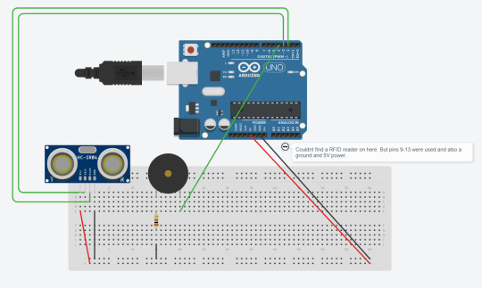
Technical Description:
RFID: The RFID component creates a magnetic field waiting for a card or tag to come into the vicinity, if one does a voltage is induced in the cards antenna coil. This then gives power to the card allowing it to return a signal to the RFID reader.
Ultrasonic Sensor: The sensor sends out a burst of ultrasound via the trig pin and the echo pin is what picks up any ultrasound waves that return, the width of the wave that returned defines the distance that the wave travelled and as it went to and from the sensor, halving that value gets the actual distance of the object from the sensor.
Button: The button has two states, LOW or 0 and HIGH or 1. When it is Low the button doesnt complete the curcuit and therefore doesnt trigger anything else but when the button is High it completes the curcuit and allows the power to pass through.
Buzzer: When the Tone function is called it tells the board, firstly, what pin the buzzer is on, and secondly what frequency the buzzer should play. Adding a delay in a loop function to the buzzer means that it can make it seem like its playing on repeat.
Code: (Includes commented out code for the button)
#include <SPI.h> #include <MFRC522.h>
#define echoPin 2 // attach pin D2 Arduino to pin Echo of HC-SR04 #define trigPin 3 //attach pin D3 Arduino to pin Trig of HC-SR04 #define buzzerPin 4 //attached buzzer to pin 4 #define RST_PIN 9 //part of the RFID #define SS_PIN 10 //part of the RFID #define NEW_UID {0xDE, 0xAD, 0xBE, 0xEF}
//loads variables from the .h file MFRC522 mfrc522(SS_PIN, RST_PIN); MFRC522::MIFARE_Key key;
//defines ultrasonic variables long duration; // variable for the duration of sound wave travel int distance; // variable for the distance measurement bool foundCard = false;
//button variables //const int buttonPin = 6; //int buttonState = 0;
void setup() { //RFID Serial.begin(9600); // Initialize serial communications with the PC while (!Serial); // Do nothing if no serial port is opened (added for Arduinos based on ATMEGA32U4) SPI.begin(); // Init SPI bus mfrc522.PCD_Init(); // Init MFRC522 card Serial.println("Warning: this example overwrites the UID of your UID changeable card, use with care!");
// Prepare key - all keys are set to FFFFFFFFFFFFh at chip delivery from the factory. for (byte i = 0; i < 6; i++) { key.keyByte[i] = 0xFF; } //Ultrasonic Sensor pinMode(trigPin, OUTPUT); // Sets the trigPin as an OUTPUT pinMode(echoPin, INPUT); // Sets the echoPin as an INPUT
//button //pinMode(buttonPin, INPUT); } void loop() { if(foundCard == false) { //ultrasonic sensor // Clears the trigPin condition digitalWrite(trigPin, LOW); delayMicroseconds(2); // Sets the trigPin HIGH (ACTIVE) for 10 microseconds digitalWrite(trigPin, HIGH); delayMicroseconds(10); digitalWrite(trigPin, LOW); // Reads the echoPin, returns the sound wave travel time in microseconds duration = pulseIn(echoPin, HIGH); // Calculating the distance distance = duration * 0.034 / 2; // Speed of sound wave divided by 2 (go and back) // Displays the distance on the Serial Monitor Serial.print("Distance: "); Serial.print(distance); Serial.println(" cm");
if(distance < 15) { tone(buzzerPin, 1000, 50); }
//BUTTON //buttonState = digitalRead(buttonPin); //if(buttonState == LOW) //{ //Serial.println("Button if statement"); //foundCard = true; //}
//RFID // Look for new cards, and select one if present if (mfrc522.PICC_IsNewCardPresent() && mfrc522.PICC_ReadCardSerial() ) { String content= ""; Serial.println("I found a card"); // Dump UID Serial.print(F("Card UID:")); for (byte i = 0; i < mfrc522.uid.size; i++) { Serial.print(mfrc522.uid.uidByte[i] < 0x10 ? " 0" : " "); Serial.print(mfrc522.uid.uidByte[i], HEX); content.concat(String(mfrc522.uid.uidByte[i] < 0x10 ? " 0" : " ")); content.concat(String(mfrc522.uid.uidByte[i], HEX)); } Serial.println(); content.toUpperCase(); if(content.substring(1) == "67 0A 6E B5") { Serial.print("Access Authorized"); foundCard = true; } } } else { Serial.println("Else Statement"); delay(10000); foundCard = false; } }
Evaluation:
I ran into some problems trying to get the first experimental stage added to the curcuit, still unsure as to why it happened but if I had given myself some more time I could have figured out how to get it to work. I left out the last stage by default as I felt I was using too many pins at this point in time for me to understand how to get a full display working. I know how it would be done but actually learning and implementing it would have taken more time than I had left.
I loved creating this build and when it came together in its first stages it properly made me smile about completing something I didnt think I could have actually done.
I feel like this can be used on a larger scale for many different uses, such as; Actual home intruder detection, or especially the Ultrasonic sensor being used as a way to notify a car driver if they are getting close to an object when reversing.
I learnt that electronics and physical computing is a lot of fun, especially when something you didnt think would works actually comes together and works as intended.
0 notes
Text
glad you’re here, friday
this morning was so foggy in the most beautiful way
six lectures back to back makes for a crazy day, by the end of the second one I wanted to make a run for it and leave
got myself a mint chocolate pulsein protein bar (which are amazing, and plant based if you’re into that) and a cappuccino, which totally did the job and made sure I didn’t fall asleep for the remainder of the lecture series
I then made it down to my GP’s office and scheduled a vaccination, and then walked home in the sun. Everyone was out by the water, drinking pimms and the sun felt so good.
Revision is going decently, I suppose. It can be frustrating at times but I keep telling myself that revision was never, and is never enjoyable, but it must be done. So you just gotta push through the frustration-cloud anyway.
Dinner this friday night was sushi with a bunch of my closest friends, followed by probably the best chocolate fondant cake in this city. Still hungry at the thought.
Daylight savings makes these days extra long and I’m so grateful for more sunny hours in the day, there’s something so special about golden-hour hitting century stone buildings and making them shine.
1 note
·
View note