#Single Roller Assembly with Web Guiding System
Explore tagged Tumblr posts
Visit Tumblr Blog
Explore Tumblr blogs with no restrictions, modern design and the best experience.
Last Seen Tumblr Blogs


Fun Fact
US Tumblr user growth rate is estimated to slow down to 4.1%.
Text
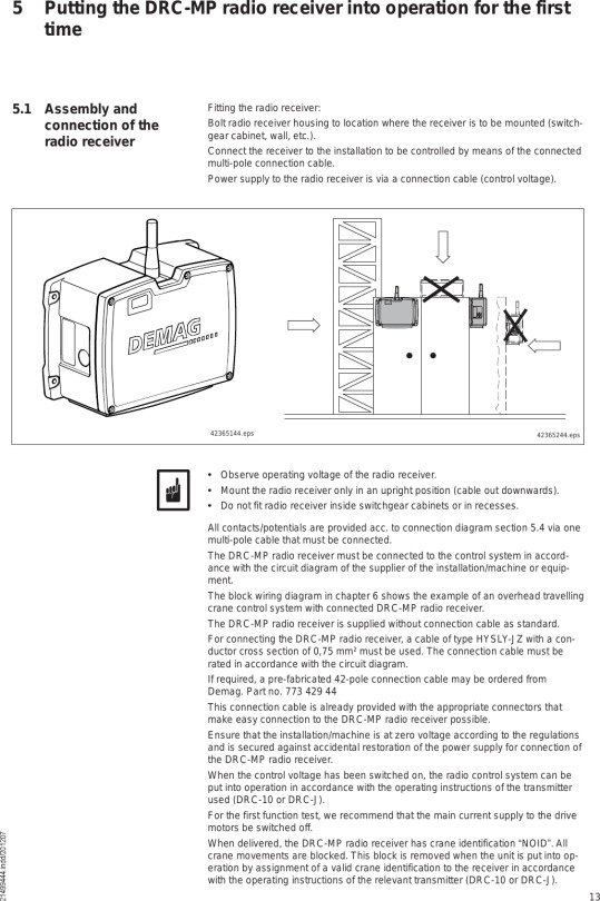
Demag Manual

Demag Cranes Operation Manual
Demag Manual User
The manual force control system is provided with a helical cable, standard length 2,8 m (extended), for transmitting the electrical signals of the D-Grip unit. This limits the suspension height to max. 3,8 m from the lower edge of the travel rail. Larger suspension heights require a special helical cable which must be specified. Demag pk10 manual. Com Please fill in the following table before first putting the chain hoist into service. 05KV 378kvar 50HZ 模块 gossenmetrawatt Sineax DME 401 146515 Hn:85-230V 冷却器 EURODIFROID KB20. Com GAUGEMASTER OO Scale price list 2015 Prices correct at time of going to press and are subject to change at any time Post free. Reading demag manual is a good habit; you can manufacture this compulsion to be such fascinating way. Yeah, reading dependence will not single-handedly create you have any favourite activity. It will be one of opinion of your life. Afterward reading has become a habit, you will not make it as disturbing comings and goings or as boring activity. Sumitomo (SHI) Demag Plastics Machinery North America, Inc. Sumitomo (SHI) Demag Plastics Machinery North America, Inc. Offers their customers products in the field of processing of plastics, in particular in the field of injection molding machines. Safety and protection of personal data is an important aspect of customer support. Mannesmann Demag Dematic AG DKUN 5-500 Kv1 F4 Chain Hoist 2200lb. Alterations or removal of any components of a part voids the day return policy. All returns must include all original parts and manuals. Once we get the item we will inspect the item to make sure it is in the same condition as we shipped it, and if it is we will issue a refund.
MAINTAIN PEAK PERFORMANCE
When you need replacement parts for your Demag cranes, go with Demag original parts. They’re manufactured to ensure that your equipment operates at peak performance. And our people are just a phone call away, ready to get the right parts in your hands as fast as possible to maintain uptime and support your business.
Europe Hotline

+49 6332 83 1100
Parts Manuals
Zweibrücken Online Parts Manuals
Search all terrain and crawler crane parts manuals
Montceau-les-Mines Online Parts Manuals


Search Montceau-les-Mines parts manuals
Web Shops
Zweibrücken Web Shop
Order parts for all terrain and crawler cranes manufactured in Zweibrücken, Germany
Demag Cranes Operation Manual
Search for your Parts contact
Demag Manual User
The Demag DH electric wire rope hoist was introduced to themarket in 1985 at the Hanover Fair. Since then, the model has served customerswith lifting needs up to 75 tons and in extreme environments. Like anyequipment used in your shop, proper maintenance and inspection is necessary tokeep you up and running to limit unnecessary downtime. One component on the DHwire rope hoist, and all wire rope hoists, that needs replaced periodically isthe rope guide. We are going to take you through how a trained servicetechnician would replace a broken or worn out rope guide and give you some tipson what prolongs the life of this component.
What does the ropeguide do on a wire rope hoist?
The function of the rope guide is to prevent the formationof loops in the wire rope while operating the hoist. The easiest way tovisualize this concept is with a failed cast on a fishing trip. Remember allthose tangles in your fishing line after a cast that wasn’t smooth? The ropeguide helps prevent that from happening. If a wire rope hoist were to formloops, it would be detrimental to the hoist unit itself. Trapped loops createslack in the wire rope so when the hook is lowered, the released slack resultsin shock-loading. Rolling over loops with consecutive wraps could result in asheared rope and a dropped load because the overlap presses the underlying wirerope against the sharp-edged drum grooves. Both situations are dangerous tocrane operators and your workforce in the area. Put safety first and rememberto inspect your wire rope hoist at recommended intervals and properly train allpersonnel.
Why does the ropeguide need replaced or adjusted?
Rope guides shipped with Demag DH hoists are made ofpoly-amide plastic. Modern rope guides are designed to include a doublepressure roller assembly where rollers press directly on the rope so it smoothlytracks into the drum groove. This results in positive and consistent spooling.Demag wire rope hoists, including the DH and DMR models, have been designed soinspection, adjustment and replacement is easily accessible. Like any otherwear part on equipment, as the rope guide plastic rides on the steel drum, theinside diameter (ID) wears over time. Once the operator or the inspector seesthe rope guide wobble during operation, it’s time to replace or adjust it.Another issue your inspection may find is a cracked rope guide. A cracked ropeguide can happen for a variety of reasons, but it’s frequently due to a loadbeing side pulled.
What is the processto adjust or replace a rope guide on the DH wire rope hoist?
The anatomy of a rope guide is simple. It has two majorsegments that overlap where they join. It has slotted holes for simple nut andbolt connections. Sometimes when you see a rope guide wobbling during use,adjusting it can fix the issue. Unfortunately, there is only so much adjustmentthat can be made until replacement is necessary. For a trained technician,adjusting the rope guide is simple. They loosen the bolts, bring the two halvescloser together and retighten the bolts so the guide can still move freely withoutbinding on the outside diameter of the drum.
As always, adjustment or replacement of a wire rope guideshould always be done by a qualified technician. Whether adjusting orreplacing, the first step is to release the pressure exerted by the rollers.This is accomplished by prying up on one half of the roller assembly to align aseries of holes across the two halves of the assembly for straight-on insertionof a pin or similar object. This pin holds back the rollers from exertingpressure and the guide can be removed. When you are installing a new ropeguide, a pin is already inserted in this hole. Whether you are adjusting orreplacing it, remember to remove the pin when finished with installation on thedrum so the rollers can exert the pressure needed to do their job.
How can I extend thelife of a rope guide?
There are many factors that determine the life of a ropeguide. Since the part is made of plastic, they are more vulnerable to theeffects of a side pull. This brings the steel wire rope in contact with theplastic guide, which can cause the guide to crack or inflict other damage. Sidepulling while lifting a load should be avoided. Always make sure your craneoperators have proper training. Another tip to extend life is regarding thetorque arm. The torque arm rides on a portion of the hoist frame. Keeping thisarea as clean as possible will prevent binding and subsequent breakage of thetorque arm. If you do follow these two suggestions, but still find that you’rereplacing the rope guide often, Demag offers reinforced rope guides made from acombination of plastic parts with metal reinforcements. Contact your authorizedDemag dealer to order.
The rope guide is an important part on your DH wire ropehoist. It assures the wire rope is spooled properly on the drum so you can liftloads safely. Keeping spare parts on hand can help you minimize downtime and beprepared to get the job done. Remember proper inspection and maintenance arekey to catching issues early. Always call in a qualified technician for the jobbecause safety is always your #1 priority.
Demag has network of authorized dealer partners across the US and Canada to help you maintain your equipment or be there to support you when you need to order parts or components. Contact us today!
0 notes
Text
Detailed guided on PCB Panel utilization
The PCB Panel benefit
A composite of printed circuit boards, i.e. Printed circuit boards that are not isolated are firmly fixed and the assembly of the printed circuit board also belongs to it, is generally taken as a printed circuit board benefit. The beauty of the layout designs must be the design of the printed circuit board use, in order to be able to use the printed circuit boards at optimal costs and stocks and configurations. The influence of the PCB benefits on the manufacturing costs of the PCB and the cost of assembly. The manufacturing costs of printed circuit boards become clear through the PCB panel inspection control, which is the right regulation of the production panel with the control used by the printed circuit boards.
In the constructed example in Figure 1, the load on panel A (6-fold use) is approx. 50% and the load on panel B (4-fold use) is approx. 70%. With suitable individual printed circuit boards and by cleverly dimensioning the panel and arranging the panels appropriately, panel utilization of up to 85% can be achieved.
Figure 1:PCB Panel utilization

Figure 2 shows the relative cost contributions in the production of printed circuit boards for a standard printed circuit board (100 * 160mm, 8 holes per cm2, 127µm track width/distance, surface: HAL) depending on the number of layers. Essentially, only the costs for drilling, cutting (scoring or milling), the electrical test, packaging and for some material components are directly dependent on the number of printed circuit boards that can be accommodated on a panel. The remaining cost components are independent of the number of printed circuit boards per panel.
Cost components in the circuit board production
Figure 2: Cost components in the production of printed circuit boards
Generally speaking, it can be stated that approx. 70% to 80% of the PCB manufacturing costs are to be regarded as fixed costs, i.e. they are independent of the number of PCBs per panel. For the configurations shown in Figure 1, this means that the 8 circuit boards (Panel B) can be manufactured and purchased almost at the total price of 6 circuit boards (Panel A). The optimal benefit size in terms of manufacturing costs is certainly dependent on the manufacturer. However, considering the commercially available panel cuts of 610 * 530mm or 1070 * 1225mm (standard sheet format) and the mounting margins and spacing required for the manufacturing process, the PCB panel utilization and thus the price formation in the PCB manufacturing for many PCB manufacturers is an optimal benefit size of approx. 245 * 285mm.
The assembly process has cost components that are directly related to the number of components per benefit and thus to the number of printed circuit boards per benefit, such as: Consumption of solder, direct SMD or THD assembly costs per component and AOI cost per component. The costs for packaging the circuit boards, an electrical function test and for separating the circuit boards from the panel are proportional to the number of circuit boards in the panel. Other cost components are almost independent of the number of printed circuit boards in use or the number of components on the printed circuit board:
Throughput time of the benefit in the soldering system, Time for paste printing, The placement machine is idle during retraction/extension or change of use. Assembly costs for PCBs benefit
Figure 3: PCB assembly costs
This reduces the processing costs in the PCB assembly for a benefit with an increasing number of PCBs in the benefit, as shown in principle in Figure 3. The following briefly examines whether maximizing the number of printed circuit boards in terms of use is always technologically sensible.
PCB Benefit Dimensions
The maximum benefit size or PCB size varies depending on the PCB manufacturer and technical equipment. Based on the standard PCB panel size cut 610 * 530mm, which is often processed, there are maximum dimensions of approx. 570 * 490mm for many manufacturers. In electronics production at CAD-UL, the maximum dimensions are specified by the machines used, provided that it is to be carried out completely mechanically:
Paste printer 600 * 600mm SMD pick and place machine 400 * 550mm Vapor phase soldering system 550 * 600mm
The following reasons speak against the processing of benefits with the maximum dimensions:
As PCB panel size increases, this also loses stability, which can also be seen depending on the PCB thickness. There is a risk that the connection points between the circuit boards break due to improper handling.
The base materials for printed circuit boards can shrink or stretch during the printed circuit board manufacturing process (dimensional stability). In addition, there are of course manufacturing tolerances in the production process of the circuit board, which can lead to an offset of copper structuring, to drilling and contour of the circuit board and to an offset from layer to layer. With a lot of know-how and by adapting the production data, the PCB manufacturers manage to keep the effects to a minimum. With very large circuit boards or with large benefits where components with small pads, e.g. B. 0.4mm pitch, placed far apart, this can lead to borderline differences between the x, y positions of the pads on the circuit boards and the associated breakouts of the steel stencils for paste printing.
Additional measures must be taken to prevent the bending of the PCB panels during transport in the transport devices, during paste printing, in the placement system and during the soldering process. The bending can lead to faulty paste printing or mechanical stress on the solder joints. In the manufacture of printed circuit boards, problems with the final inspection and the electrical test arise with increasing dimensions.
If there is a requirement not to allow failure circuit boards in the panel, maximizing the number of circuit boards in the panel can lead to a significant loss in yield and thus to a price increase for the single circuit board.
Connection of the circuit boards and benefit separation
The design of the benefits must be reconsidered and specified during the PCB layout phase so that there are no surprises later during the assembly process. Basically, a decision for a procedure must be made: scoring, milling or a combination of both. The position and orientation of the components relative to the scratching trench or the milling ridges must be selected so that the force applied when the panels are separated is as small as possible. The copper must be set back sufficiently from the scoring trenches or perforation holes for the burrs in order to avoid water exposure. Ultimately, the layout designer is also responsible for sufficient stability of use during all machining processes and for the joint and coordinated optimization of the manufacturing and assembly costs of the printed circuit board.
Connection of printed circuit boards and benefit separation for printed circuit boards with a straight and continuous contour with a minimum of two opposite parallel sides see Figure 4 and if there are no special requirements with regard to edge roughness, the scoring or notch milling process can be used. Trenches lying one above the other are carved on both sides of the printed circuit boards. The notch angle is usually 30˚, the notch depth depends on the board thickness and the remaining core thickness is approximately 0.4mm. The scribing process is no longer useful for circuit board thicknesses greater than 2.0 mm. In order to reduce the mechanical stress when separating the printed circuit boards from the panel to a minimum, CAD-UL uses a scratch PCB panel separator with a fixed and a roller knife.
Figure 4: PCB Scoring benefits
For circuit boards with irregular contours or if there are increased demands regarding edge roughness and dimensional accuracy, see Figure 5, the circuit board contour must be milled. The diameter of the milling cutters, usually 2.0mm or 2.4mm, for edge processing should be specified because the blanking process must be set to this milling width. Bars must remain during milling in order to connect the circuit boards to one another or to the utility frame. The number, position, and width of the webs must be carefully determined depending on the use or milling benefits of the printed circuit board size and thickness, in order to be able to guarantee sufficient mechanical stability during all processing operations, as well as to separate the printed circuit boards from the use with little mechanical To be able to carry out stress on the solder joints and components. The webs can also be scratched or provided with perforation holes inside, on or outside the circuit board contour, see Figure 6, in order to be able to further reduce the stress effect when cutting.
Figure 5: PCB Milling benefits
With CAD-UL, the webs are either punched out by a pneumatically working web separator with a hook knife, or the circuit boards are separated from one another by milling. Depending on the separation process and the position of the perforation holes, sharp-edged remnants of the webs can remain on the circuit board, which can lead to injuries. These are to be removed after the separation.
Figure 6: Variants of router bars
A common feature of all depaneling processes is that the circuit board deforms at the separation points due to the mechanical action during the separation and that forces are exerted on the components and the soldering points. These can lead to component defects, in particular hairline cracks in SMD ceramic capacitors. Under certain circumstances, these defects are not immediately visible or have no effect, but only lead to malfunctions of the affected components after a long time.
Mixed benefits are defined as benefits that combine different printed circuit boards with identical layer structure and identical manufacturing technology. The motivation for this is clear, printed circuit boards are only charged once and only one paste printing stencil is required for a printed circuit board with SMD on one side. If, however, the Gerber data set provides several parts lists and several pick & place data sets for the benefit, in which reference names may be assigned more than once, these data sets must be combined with effort and risk of error by the work preparation department for electronics production in order to effectively create components shopping and to be able to effectively consider the benefits as an assembly project. Most of the time, the different printed circuit boards are installed in the device in one device and these printed circuit boards are therefore required in the same number of pieces or in a fixed number of pieces. However, since raw circuit boards already fail in use and errors can occur during the assembly of printed circuit boards, the planned quantity ratio cannot be guaranteed after the end of production. This can lead to problems, particularly with series assembly. The savings in one-off costs at the start of the project may later be expensive.
Figure 7: Mixed benefit
All those involved, the circuit board layout, the circuit board manufacturer and the circuit board assembler should carefully weigh the advantages and disadvantages of a mixed-use at the start of the project and determine an optimal procedure together.
In order to make optimal use of the space on a production panel, it is also possible to use irregularly shaped printed circuit boards, e.g. L-shaped or T-shaped, to be arranged rotated to each other on a PCB panel with 90 mit or 180˚. However, since printed circuit boards have preferred directions for paste printing and wave soldering, it should be checked whether this procedure also guarantees an optimal assembly process.
Last but not least, a printed circuit board that is to be produced and assembled individually, e.g. Components placed too close to the edge or where there is no more space for fiducial brands and which therefore must be provided with a receiving edge on at least two opposite sides are referred to as benefits.
Please do not hesitate to contact us if you have any questions about the design of the benefits or support in the creation of the benefits. Our employees in the areas of PCB layout and work preparation are always at your side with advice and action.
Dimensions of single circuit board and delivery benefits
Single PCB
Please select this option if your circuit board consists of a single circuit pattern. We always mill individual circuit boards. The circuit board may contain internal cutouts as long as it does not separate the circuit diagram. Otherwise, we speak of a PCB benefit.
If your PCB is smaller than 30x15mm, please put it in a delivery benefit. For this, we offer you the option “PCB Delivery benefit with online configuration”.
Delivery benefits
Delivery benefit from file or plan:
The same applies to multi-use if you want to order different conductor patterns in one use.
Delivery benefits with online configuration:
Do you have the data of a single circuit board and no benefit drawing, but would like to have your circuit board in the delivery benefit? Then simply tell us in the configurator how we can design the benefits. If you need predetermined breaking holes, please bring them into the single image in advance.
You can find more on the definition of a delivery benefit in our tutorial!
Registration marks in the edge of the sheet
On request, we can introduce registration marks in the delivery area of your printed circuit boards. Place it like 3 copper pads with a diameter of 1.00 mm in the middle of the edge of the PCB panel. In the solder mask, these are exempted with 2.00 mm.
Bad parts in the delivery benefit
In the delivery benefit, it can happen that individual circuit boards are struck out by our quality assurance if the quality does not meet our standard. We never paint more than 50% of the printed circuit boards on a delivery benefit. We also fill in the missing number of items by sending more delivery benefits than you ordered. So that you always get at least the desired number at the end.
Features of flex PCB
A circumferential edge of ≥ 7.50 mm is absolutely necessary. If there is a copper-free surface, the delivery benefit edge is always rostered onto the top and bottom. This prevents the PCB from warping. The edge of the delivery benefit is always coated on both sides with flex lacquer (even with a 1F structure).
General information on dimensions
The size of your circuit board is determined by the measurement from center contour to center contour. We, therefore, recommend using a contour line of 200 µm to avoid ambiguities.
At Moko Technology, your printed circuit boards can be machined using notches, milling or a combination of notches and milling. We carry out milled PCBs.
When milling a multiple-use, your printed circuit board remains connected in the benefit by means of retaining bars. The standard cutters are 1.60mm, 2.00mm or 2.40mm.
When notching, MOKO Technology place your printed circuit boards in the delivery benefit.
0 notes
Text
Exactly How Do InkJet Printers Work
The printers making use of inkjet technology were initially introduced in the late 1980s and also since then have actually gotten much appeal while growing in performance and also decreasing in rate. They are the most usual kind of computer system printers for the basic customer because of their inexpensive, top quality of outcome, capacity of printing in brilliant color, and convenience of use. Each printer which works with inkjet technology places incredibly small droplets of ink onto paper to produce a message or an image. In the personal as well as local business computer market, inkjet printers currently predominate. Inkjets are typically economical, silent, moderately quick, and also numerous designs can produce premium quality output. Like many modern technologies, the present-day inkjet is improved the development made by many earlier versions. Among several factors, Epson, Hewlett-Packard as well as Canon can assert a considerable share of credit history for the development of the modern inkjet innovation.
UV printen
In the globally consumer market, four suppliers represent most of inkjet printer sales: Canon, Hewlett-Packard, Epson, as well as Lexmark. The common inkjet printer generally includes inkjet printhead setting up, paper feed setting up, power supply, control circuitry and also interface ports. The inkjet printhead setting up has a number of elements. Among them is the printhead which is the core of the inkjet printer and also consists of a collection of nozzles that are utilized to spray decreases of ink. An additional printhead element is the inkjet cartridge or inkjet storage tank. Depending upon the producer and model of the printer, ink cartridges been available in numerous mixes, such as different black and also shade cartridges, shade and black in a single cartridge or perhaps a cartridge for each ink shade. The cartridges of some inkjet printers consist of the print head itself. The printhead in addition to the inkjet cartridge/s are moved back as well as forth across the paper by device called a stepper motor making use of a special belt.
iUV1200 UV printer
Some printers have an extra stepper motor to park the print head setting up when the printer is not in use which indicates that the print head setting up is limited from accidentally moving. The print head assembly utilizes a stabilizer bar to ensure that movement is accurate and controlled. Among the paper feed assembly elements is the paper tray or/and paper feeder. A lot of inkjet printers have a tray that the paper is filled right into. The feeder typically snaps open at an angle on the back of the printer, permitting the paper to be put in it. Feeders typically do not hold as much paper as a traditional paper tray. A set of rollers pull the paper in from the tray or feeder as well as breakthrough the paper when the print head assembly awaits one more pass after which one more action electric motor powers the rollers to relocate the paper in the precise increment needed to make certain a continuous picture is published.
While earlier printers typically had an outside transformer, the majority of printers marketed today use a common power supply that is incorporated right into the printer itself. A tiny but innovative quantity of circuitry is built into the printer to manage all the mechanical aspects of operation, along with decode the details sent out to the printer from the computer. It is linked to the computer system by a wire through the user interface port. The user interface port can be either parallel port, USB port or SCSI port. The identical port is still used by lots of printers, however a lot of newer printers use the USB port. A couple of printers attach utilizing a serial port or little computer system user interface (SCSI) port. Different types of inkjet printers exist based upon the approach they make use of to deliver the beads of ink. There are three main inkjet innovations presently utilized by printer suppliers. The thermal bubble technology used by producers such as Canon and Hewlett Packard is frequently referred to as bubble jet. In a thermal inkjet printer, tiny resistors develop warm, as well as this heat vaporizes ink to create a bubble.
As the bubble expands, several of the ink is pressed out of a nozzle onto the paper. When the bubble breaks down, a vacuum is produced. This draws more ink right into the print head from the cartridge. A normal bubble jet print head has 300 or 600 little nozzles, as well as all of them can terminate a droplet concurrently. Thermal inkjet modern technology is used almost exclusively in the customer inkjet printer market. The ink utilized is usually water-based, pigment-based or dye-based yet the print head is generated normally at much less cost than various other ink jet innovations. Unlike the bubble jet modern technology, the piezoelectric technology, patented by Epson, utilizes piezo crystals. A crystal is located at the back of the ink storage tank of each nozzle. The crystal obtains a tiny electric charge that triggers it to vibrate. When the crystal shakes inward, it compels a tiny quantity of ink out of the nozzle. When it vibrates out, it draws some even more ink into the tank to change the ink sprayed out.
The continual inkjet technique is made use of commercially for marking as well as coding of products as well as plans. The very first patent on the suggestion is from 1867, by William Thomson. The initial business model was presented in 1951 by Siemens. In continuous inkjet modern technology, a high-pressure pump routes fluid ink from a reservoir via a tiny nozzle, producing a continuous stream of ink beads. A piezoelectric crystal causes the stream of fluid to break into droplets at regular periods. The ink beads are subjected to an electrostatic field created by a charging electrode as they create. The area is varied according to the level of drop deflection wanted. This causes a controlled, variable electrostatic fee on each droplet. Billed droplets are separated by one or more uncharged "guard droplets" to lessen electrostatic repulsion between neighboring beads. The billed droplets are then guided (deflected) to the receptor product to be printed by electrostatic deflection plates, or are allowed to continue undeflected to a collection gutter for reuse.
Continual inkjet is among the earliest inkjet technologies in operation and is fairly mature. Among its benefits is the very high rate (~ 50 m/s) of the ink droplets, which permits the ink goes down to be thrown a long distance to the target. Another advantage is liberty from nozzle clogging as the jet is constantly in operation When printing is begun, the software program application sends out the information to be published to the printer vehicle driver which translates the information right into a style that the printer can understand and also checks to see that the printer is on the internet and offered to publish. The information is sent out by the chauffeur from the computer to the printer through the connection user interface. The printer obtains the data from the computer system. It stores a specific amount of information in a buffer. The buffer can range from 512 KB arbitrary accessibility memory (RAM) to 16 MB RAM, depending on the printer model. Buffers serve because they permit the computer to completed with the printing procedure swiftly, instead of needing to wait on the actual web page to print. If the inkjet printer has been idle for an amount of time, it will generally go through a short cleansing cycle to ensure that the print heads are tidy. When the cleansing cycle is complete, the inkjet printer is ready to begin printing. The control wiring activates the paper feed stepper electric motor.
This involves the rollers, which feed a sheet of paper from the paper tray/ feeder right into the printer. A tiny trigger system in the tray/ feeder is depressed when there is paper in the tray or feeder. If the trigger is not depressed, the inkjet printer illuminate the "Out of Paper" LED and also sends out a sharp to the computer system. Once the paper is fed right into the inkjet printer and positioned at the start of the page, the print head stepper motor uses the belt to move the print head setting up across the page. The electric motor stops for the merest fraction of a second each time that the print head sprays dots of ink on the page and then relocates a tiny bit prior to quiting once again. This stepping takes place so quick that it looks like a continuous motion. Numerous dots are made at each stop. It sprays the CMYK (cyan/ magenta/ yellow/ black) colors in accurate amounts to make any type of other color possible. At the end of each complete pass, the paper feed stepper motor advances the paper a portion of an inch. Depending upon the inkjet printer design, the print head is reset to the beginning side of the page, or, in most cases, merely reverses direction and starts to move back across the web page as it prints. This procedure proceeds until the web page is published. The time it requires to print a web page can vary commonly from printer to printer. It will likewise vary based upon the complexity of the web page as well as size of any kind of images on the web page. As soon as the printing is full, the print heads are parked. The paper feed stepper electric motor rotates the rollers to complete pushing the finished page right into the outcome tray.
Most inkjet printers today utilize inkjet inks that are extremely fast-drying, so that you can quickly grab the sheet without smudging it. Compared to earlier consumer-oriented printers, inkjet printers have a variety of benefits. They are quieter in procedure than effect dot matrix printers or daisywheel printers. They can publish finer, smoother information through greater printhead resolution, and several inkjet printers with photorealistic-quality shade printing are extensively offered. In contrast to a lot more costly technologies like thermal wax, color sublimations, and also printer, the inkjet printers have the advantage of almost no workout time and also lower expense per web page (other than when compared to printer).
The negative aspects of the inkjet printers consist of flimsy print heads (vulnerable to blocking) and also expensive inkjet cartridges. This usually leads value-minded consumers to take into consideration laser printers for medium-to-high quantity printer applications. Other negative aspects consist of ink blood loss, where ink is carried laterally away from the preferred place by the capillary effect; the outcome is a sloppy look on some types of paper. A lot of inkjet printer manufacturers also market special clay-treated paper developed to decrease blood loss. Due to the fact that the ink used in many inkjet cartridges as well as ink storage tanks is water-soluble, treatment has to be taken with inkjet-printed papers to avoid also the smallest drop of water, which can create severe "blurring" or "running.".
Besides the well known little inkjet printers for home and office, there is a market for specialist inkjet printers; some being for page-width layout printing, and also a lot of being for broad format printing. "Page-width format" indicates that the print width varies from concerning 8.5" to 37". "Wide format" indicates that these are inkjet printers ranging in print size from 24" approximately 15'. The application of the page-width inkjet printers is for printing high-volume company interactions that have a lesser requirement for showy format and shade. Especially with the enhancement of variable information modern technologies, the page-width inkjet printers are important in invoicing, tagging, and personalized magazines and papers. The application of a lot of the wide layout inkjet printers is for publishing advertising and marketing graphics; a minor application is printing of styles by engineers or designers.
0 notes
Text
LA Small-Block Kicking Some LS Butt on the Dyno
Let’s cut to the chase: The LA small-block racing engine we’ve been following, built by Michigan’s Valley Performance for the Race Engine Challenge, took home the gold.
Based on average horsepower per cubic inch, the 376-inch underdog surprised and overpowered more than a few LS builders in the event, punching out 1.963 hp for each genuine Mopar cube and claiming the class win.
“We were confident we had a competitive combination and would give the LS engines and other well-developed engines a run for their money,” says Jack Barna, Valley Performance’s owner. “But it was still somewhat of a surprise to see our engine come out on top. It had something to prove and really did.”
As we detailed in the first installment of this story, the engine was built for the inline-valve class in the competition, which had a displacement range of 370 to 490 ci. The other class was for canted valve/Hemi designs. And while those engines expectedly posted big peak numbers, Valley Performance’s output was right with them when it came to power-per-inch.
“Our number was within 1 hp of the top Hemi engine,” says Barna. “So when it came to overall output, our LA really brought it home.”
The engine posted an average horsepower rating of 737 hp, which was about 4.5 percent lower than Valley Performance’s test pulls on a different dyno. Barna attributed the difference to a variety of contributors: a different dyno, different atmospheric conditions, a different altitude correction factor and more, but the bottom line is the engine squeezed out more per cube than its rivals.
“We believed a smaller engine would be more efficient when it comes to making the most average power per displacement, with less friction and more airflow per cubic inch,” he says. “The results speak for themselves.”
Valley Performance started with an early Magnum 360 block that was reinforced with Hard Blok in the water jackets and underwent a number of modifications for windage-reducing oil control. Valley Performance also had a splayed four-bolt main caps made for it to provide extra support for the mains. The cylinder was bored out to 4.100 inches to unshroud the valves.
In our first installment, we focused on the engine’s block enhancements and short-block assembly, outlining a number of unique and custom modifications designed to shore up the LA’s foundation. Valley Performance started with an early Magnum 360 block, largely for its overall strength and taller lifter bores.
The block mods and short-block details included:
The cylinder were overbored from 4.000 inches to 4.100, mostly to unshroud the valves.
The stroke was reduced slightly, from 3.580 inches to 3.556 inches, to achieve the desired displacement and use 2.100-inch rod journals.
The water jackets were partially filled with Hard Blok to promote optimal ring sealing.
Windows were cut into the main web area to alleviate windage.
Custom, splayed four-bolt main caps were made to provide greater main bearing support.
A lifter valley reinforcement plate was added to tie the valley to the block’s rear bulkhead for additional strength.
Extensive oil-control block modifications were made to reduce windage, including closing off the lifter valley from oil drain back and drilling an oil drain tunnel through the block to drain oil externally to the oil pan.
Bullet roller camshaft with 0.775/0.774-inch lift and 255/265 degrees duration.
An Eagle forged crankshaft with the counterweights refined to minimize windage.
Eagle 6.250-inch H-beam connecting rods with 0.927-inch pins (stock 360 rods are 6.123 inches long), to reduce piston height.
Custom Ross gas-ported pistons with thermal and friction coatings. The heads were custom made, per Valley Performance’s molds of the cylinder head combustion chambers
A compression ratio of 11.66:1.
That brings us to the rest of the buildup: airflow. In the Race Engine Challenge, the engine would be judged on its average power production between 4,000 and 7,500 rpm. That would take the basic, truck-based Magnum 360 out of its comfort zone, when it came to engine speed.
“That’s one of the reasons we took so many precautions with the block,” says John Lohone, the engine’s co-builder. “The flip side of that is we needed exceptional airflow to achieve the power numbers we were aiming for at that rpm level.”
With the rules stipulating carburetion and natural aspiration, that proved more than a small challenge, as aftermarket parts options aren’t as plentiful as they are for other engine families such as the RB family.
“Before we agreed to go with the LA-based small-block, we took a long, hard long at the available parts out there, knowing we’d need a killer set of heads,” says Barna. “When it came down to it, the recent Edelbrock Victor small-block head sealed the deal. Without them, I don’t think we could have achieved the airflow we needed.”
There was another problem: drawing enough air and fuel into the heads.
“A single-plane, single-carb intake just wasn’t going to get it done,” says Barna. “We opted to modify a 25-year-old, W2-style Holley Pro Dominator tunnel ram and make it fit the Edelbrock Victor heads.”
Besides adapting the manifold to the heads, extensive work was done to reshape the tunnel-ram’s passages in order to blend seamlessly with the heads’ intake ports.
“We believe line of sight is important for the intake path,” says Lohone. “The changes made with the manifold provided the air/fuel mixture an unobstructed path to the combustion chambers, with excellent velocity.”
Topped with a pair of 880-cfm Holley four-barrels, the engine spun to 7,500 rpm in testing and produced 771 hp and 601 lb-ft of torque. It was a result that bolstered Valley Performance’s confidence as they headed in to the Race Engine Challenge, even if the dyno results during the competition didn’t quite match.
“All the engines were competing on the same dyno and test conditions, so we were satisfied with the parity of the challenge,” said Barna. “When it was all said and done, our engine produced the greatest average power per displacement, which was the goal in the first place.”
The little LA engine that could slayed some bigger competitors and raised some eyebrows, all while earned some well-deserved respect for the Mopar small-block.
Inside the block is an Eagle forged crankshaft the slightly reduces the stroke from 3.580 inches to 3.556 inches. The rods and pistons include Eagle 6.250-inch H-beam rods and custom Ross forged pistons that contribute to an 11.66:1 compression ratio. The camshaft is a Bullet roller unit with 0.775/0.774-inch lift and 255/265 degrees duration.
The relatively new Edelbrock Victor cylinder head is credited with helping push this small block project to the winner’s circle. They offer large, 225cc intake ports, raised exhaust ports and a revised 16-degree valve angle (stock is 18 degrees). Out of the box, the head is good for about 345 cfm on the intake side and 237 cfm through the exhaust ports.
Valley Performance enhanced airflow in the new heads by opening up the walls a bit to eliminate the pushrod inch, along with a little guide work, resulting in a strong 372 cfm at 28 inches of water. Note, too, the 5/16-inch bolt at the upper left of the stock bolthole. It was to bolt up the W2-style tunnel ram intake manifold.
Here’s the outside view of a modified intake port, showing the welding required to close up the wall after the pushrod pinch inside was eliminated.
Thermal-coated exhaust ports help keep in heat and move air faster. Valley Performance says the ports flowed well stock, but they nonetheless opened the bowls and worked on the short-turn radius, bumping flow to 265 cfm.
Out of the box, the Edelbrock Victor heads have 58cc combustion chambers, complemented with Valley’s insertion of 2.175-inch hollow-stem intake valves and 1.600-inch exhaust valves. Valley Performance blended the valve seats and combustion chamber area to enhance airflow, ending up with 61.5cc chambers.
For oil control, the oil drains in the heads were plugged, forcing the oil to exit externally through the front and rear of the head casting and preventing it from draining back into the lifter valley.
Moving up to the valvetrain is a set of PAC Racing Springs dual-coil springs with titanium retainers. Specs include an installed height of 1.88 inches and a 675-pound spring rate.
The pushrods are strong, 3/8-inch-diameter with 0.120-inch walls, from Smith Brothers.
Hughes Engines supplied the 1.7-ratio roller rocker arm assemblies, which have been cryogenically treated to enhance strength. They’re actually big block Wedge-style assemblies to accommodate the offset that comes with the heads’ 0.600-inch-longer intake valves.
The intake manifold was a large challenge for the project. Besides adapting the W2-style bolt pattern to the W5-pattern heads, the passages had to be reshaped to match the intake ports. It took Valley Performance’s Jack Barna two months of scouring the internet before he found the vintage Holley Pro Dominator tunnel ram.
The manifold’s intake runners were originally D-shaped and didn’t line up with the heads’ intake ports, so Valley Performance went to work reshaping them until they did. The goal was to make the runners blend with the ports, with the larger radius of each runner at the top to optimize velocity.
This close-up of one of the tunnel-ram’s intake runners shows the mix of the grinding, welding, and epoxy work that was required to reshape it for a straight line-of-sight path to the intake port.
Despite the comparatively small 376ci displacement, the airflow capability of the heads and intake manifold demanded significant fuel and air delivery, so a pair of 880-cfm four-barrels from Pro Systems Carbs (with annular boosters) were crafted by Patrick James.
The carbs are used with anti-reversion plates — also known as shear plates — to help prevent high-rpm airflow reversion. They’re designed to redirect hot gases that can rise into the manifold via camshaft overlap; and with a tight lobe separation angle of 106 degrees on this engine’s cam, that’s a concern.
An MSD crank trigger system was selected for more precise cylinder-to-cylinder ignition timing. With it, the conventional distributor mounted on the engine is essentially gutted, containing only the rotor and shaft to support the secondary ignition.
The headers are from Schoenfeld, with 1-3/4-inch-to-1-7/8-inch stepped primary tubes and 3-1/2-inch collectors. Valley Performance cut the collectors from the primaries and experimented with various primary lengths on the dyno, finding the original length delivered the best average performance.
Here’s the final assembly. Note the oil drain-back hoses at the front and rear of the heads. Plenty of pre-challenge testing found the engine liked 34 degrees of total timing and delivered peak ratings of 771 horsepower and 601 lb.-ft. of torque.
On the dyno at the competition, the engine Valley Performance nicknamed Mopar Disadvantage spun its way to the win, recording 738 hp — or 1.962 hp per cubic inch. It’s performance that proved a point and demonstrated what two knowledgeable Mopar builders and a carefully constructed plan could achieve.
The post LA Small-Block Kicking Some LS Butt on the Dyno appeared first on Hot Rod Network.
from Hot Rod Network https://www.hotrod.com/articles/la-engine-kicking-ls-butt-dyno/ via IFTTT
0 notes
Link

We are Manufacturer Of Web Guiding Systems, Web Guiding System, Hydro Pneumo Web Aligner Unit, Edge Guiding System, Line Guiding System, Single Roller Assembly with Web Guiding System, Unwinding Machine with Web Guiding System, Chaser Guiding System with Web Guiding System, High-Performance Web Guide with International Standards. Web Guiding System, Hydro Pneumo Web Aligner Unit, High-Performance Web Guide 0.5 – 3 hp, Tension Control Web Guiding System Manufacturer India.
#Web Guiding Systems#Web Guiding Systems Manufacturer#Web Guiding System#Web Guiding System Manufacturer#Web Guiding#Web Guiding Unit#Web Guide System#Web Guide Systems#Web Guide unit#Web Guide#Edge Guiding System#Web Guiding Units
0 notes
Link
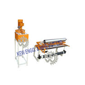
We have developed a state-of-the-art manufacturing unit to make an assortment of Center Guiding System With Web Guiding System. Different Types of Edge Guiding System, Web Guide System, Web Aligner, Single Roller Assembly with Web Guiding System, Chaser Guiding System with Web Guiding System, Unwinding Machine with Web Guiding System, Rewinding Machine with Web Guide System. Our products are manufactured and designed using high quality material and cutting-edge technology for the better development of our products.
#Center Guiding System#Center Guiding System with Web Guiding System#Web Aligner Unit#Web Guiding System#Web Guiding System Manufacturer#Web Guide System#Web Guide Systems#Web Guide System manufacturer#Web Guide Unit#Web Aligner#Web Aligner System#Web Guiding Unit
0 notes
Text
Just How Do InkJet Printers Work
The printers making use of inkjet innovation were initially presented in the late 1980s and since then have actually obtained much popularity while expanding in efficiency and also decreasing in rate. They are the most usual type of computer system printers for the basic customer due to their low cost, excellent quality of outcome, capability of printing in dazzling color, and also simplicity of usage. Each printer which services inkjet technology places extremely small droplets of ink onto paper to create a message or an image. In the individual as well as small company computer market, inkjet printers presently predominate. Inkjets are usually economical, quiet, reasonably quickly, and also numerous models can generate top quality output. Like many contemporary innovations, the contemporary inkjet is improved the progression made by lots of earlier versions. Amongst numerous contributors, Epson, Hewlett-Packard and also Canon can claim a considerable share of credit scores for the development of the contemporary inkjet modern technology.
iUV600s UV printer
In the worldwide consumer market, 4 producers account for the majority of inkjet printer sales: Canon, Hewlett-Packard, Epson, as well as Lexmark. The regular inkjet printer generally consists of inkjet printhead setting up, paper feed assembly, power supply, control circuitry and also interface ports. The inkjet printhead assembly includes a number of elements. One of them is the printhead which is the core of the inkjet printer as well as includes a series of nozzles that are used to spray decreases of ink. An additional printhead part is the inkjet cartridge or inkjet container. Depending upon the maker and also design of the printer, ink cartridges come in various combinations, such as separate black as well as color cartridges, shade and also black in a single cartridge and even a cartridge for each ink shade. The cartridges of some inkjet printers include the print head itself. The printhead along with the inkjet cartridge/s are returned and forth across the paper by device called a stepper motor using an unique belt.
iUV1200 UV printer
Some printers have an extra stepper motor to park the print head setting up when the printer is not being used which implies that the print head assembly is restricted from inadvertently relocating. The print head assembly uses a stabilizer bar to make sure that movement is precise and also controlled. One of the paper feed setting up elements is the paper tray or/and paper feeder. Many inkjet printers have a tray that the paper is packed right into. The feeder generally snaps open at an angle on the back of the printer, permitting the paper to be put in it. Feeders normally do not hold as much paper as a traditional paper tray. A set of rollers draw the paper in from the tray or feeder as well as development the paper when the print head setting up is ready for one more pass after which one more action motor powers the rollers to relocate the paper in the exact increment needed to make sure a continual photo is published.
While earlier printers frequently had an outside transformer, the majority of printers sold today make use of a standard power supply that is incorporated into the printer itself. A tiny but innovative amount of wiring is built into the printer to regulate all the mechanical facets of operation, as well as translate the info sent to the printer from the computer. It is attached to the computer by a cord via the user interface port. The user interface port can be either identical port, USB port or SCSI port. The parallel port is still utilized by several printers, however many newer printers make use of the USB port. A few printers attach utilizing a serial port or tiny computer system user interface (SCSI) port. Different kinds of inkjet printers exist based on the approach they use to provide the beads of ink. There are 3 primary inkjet innovations currently utilized by printer makers. The thermal bubble technology utilized by suppliers such as Canon and Hewlett Packard is commonly referred to as bubble jet. In a thermal inkjet printer, small resistors produce warm, and this warmth vaporizes ink to produce a bubble.
As the bubble expands, a few of the ink is pressed out of a nozzle onto the paper. When the bubble falls down, a vacuum is created. This pulls even more ink right into the print head from the cartridge. A regular bubble jet print head has 300 or 600 tiny nozzles, and all of them can fire a bead simultaneously. Thermal inkjet innovation is used almost exclusively in the consumer inkjet printer market. The ink utilized is normally water-based, pigment-based or dye-based yet the print head is created normally at much less price than various other ink jet technologies. In contrast to the bubble jet technology, the piezoelectric modern technology, patented by Epson, utilizes piezo crystals. A crystal lies at the back of the ink storage tank of each nozzle. The crystal gets a small electrical fee that creates it to vibrate. When the crystal shakes internal, it forces a little quantity of ink out of the nozzle. When it vibrates out, it draws some even more ink into the tank to replace the ink splashed out.
The continual inkjet technique is made use of readily for noting and also coding of products and also packages. The very first patent on the suggestion is from 1867, by William Thomson. The initial commercial design was presented in 1951 by Siemens. In continual inkjet modern technology, a high-pressure pump guides liquid ink from a reservoir via a tiny nozzle, creating a constant stream of ink beads. A piezoelectric crystal triggers the stream of liquid to break into beads at routine periods. The ink beads are subjected to an electrostatic area produced by a charging electrode as they develop. The field is diverse according to the level of decrease deflection wanted. This causes a controlled, variable electrostatic fee on each droplet. Charged droplets are separated by one or more uncharged "guard beads" to decrease electrostatic repulsion in between bordering beads. The billed beads are then routed (dispersed) to the receptor material to be printed by electrostatic deflection plates, or are allowed to continue undeflected to a collection rain gutter for reuse.
Continuous inkjet is among the earliest inkjet technologies in operation as well as is fairly fully grown. Among its benefits is the very high velocity (~ 50 m/s) of the ink droplets, which allows the ink goes down to be thrown a far away to the target. One more benefit is flexibility from nozzle blocking as the jet is always being used When printing is started, the software application sends out the information to be printed to the printer chauffeur which translates the data right into a style that the printer can understand and checks to see that the printer is on the internet and also readily available to publish. The data is sent out by the chauffeur from the computer to the printer by means of the link user interface. The printer obtains the information from the computer system. It stores a certain quantity of information in a buffer. The buffer can range from 512 KB random accessibility memory (RAM) to 16 MEGABYTES RAM, depending upon the printer design. Barriers are useful since they permit the computer to finish with the printing procedure rapidly, rather than needing to wait on the actual page to print. If the inkjet printer has been still for a period of time, it will usually go through a brief cleaning cycle to see to it that the print heads are clean. Once the cleansing cycle is total, the inkjet printer is ready to start printing. The control wiring turns on the paper feed stepper electric motor.
This involves the rollers, which feed a sheet of paper from the paper tray/ feeder right into the printer. A small trigger mechanism in the tray/ feeder is dispirited when there is paper in the tray or feeder. If the trigger is not dispirited, the inkjet printer brighten the "Out of Paper" LED as well as sends out a sharp to the computer. As soon as the paper is fed into the inkjet printer as well as placed at the beginning of the page, the print head stepper electric motor uses the belt to relocate the print head setting up throughout the web page. The motor pauses for the slightest fraction of a second each time that the print head sprays dots of ink on the page and then relocates a tiny bit before quiting again. This tipping occurs so quickly that it appears like a constant movement. Several dots are made at each stop. It sprays the CMYK (cyan/ magenta/ yellow/ black) colors in exact total up to make any type of various other color conceivable. At the end of each full pass, the paper feed stepper electric motor advancements the paper a fraction of an inch. Relying on the inkjet printer model, the print head is reset to the start side of the web page, or, in most cases, just turns around direction and also begins to move back across the web page as it prints. This procedure continues till the web page is printed. The time it takes to publish a web page can vary commonly from printer to printer. It will also vary based on the intricacy of the web page and also size of any photos on the page. As soon as the printing is full, the print heads are parked. The paper feed stepper motor spins the rollers to finish pushing the finished page into the result tray.
A lot of inkjet printers today utilize inkjet inks that are very fast-drying, to make sure that you can right away grab the sheet without smudging it. Compared to earlier consumer-oriented printers, inkjet printers have a variety of advantages. They are quieter in operation than influence dot matrix printers or daisywheel printers. They can print finer, smoother details via higher printhead resolution, and several inkjet printers with photorealistic-quality color printing are extensively readily available. In comparison to a lot more pricey technologies like thermal wax, color sublimations, as well as laser printers, the inkjet printers have the benefit of virtually no warm-up time and reduced expense per web page (except when compared to printer).
The disadvantages of the inkjet printers include lightweight print heads (prone to clogging) and also pricey inkjet cartridges. This typically leads value-minded consumers to consider laser printers for medium-to-high volume printer applications. Other negative aspects consist of ink blood loss, where ink is carried sideways away from the preferred area by the capillary effect; the result is a sloppy look on some kinds of paper. Many inkjet printer suppliers likewise offer special clay-treated paper developed to lower bleeding. Because the ink used in many inkjet cartridges and ink containers is water-soluble, treatment must be taken with inkjet-printed records to prevent even the tiniest decrease of water, which can cause serious "blurring" or "running.".
0 notes