#atmega2560 r3 board
Explore tagged Tumblr posts
Visit Tumblr Blog
Explore Tumblr blogs with no restrictions, modern design and the best experience.
Last Seen Tumblr Blogs


Fun Fact
Tumblr.com rank in the US is 25.
Text
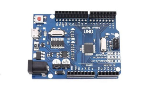
Arduino Atmega 2560 R3 Microcontroller Board
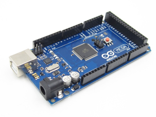
With the MAX3421e IC, the Mega 2560 Atmega2560-16au compatible with Arduino is a microcontroller board based on the Arduino Atmega 2560 R3.
With a total of 54 digital input/output pins (including 15 PWM outputs), 16 analog inputs, and 4 UARTs, the MEGA ADK is jam-packed with features. It also boasts a 16 MHz crystal oscillator and comes equipped with a USB connection, power jack, ICSP header, and reset button. Based on the Arduino Atmega 2560 r3, this board shares many similarities with its counterparts, including the ATmega8U2 program that serves as a USB-to-serial converter. In fact, the Mega ADK revision 3 even includes a resistor that conveniently pulls the 8U2 HWB line to ground for easier DFU(Device Firmware Upgrade) mode access.
New features on the board include:
As part of the 1.0 pin-out, the shields will be able to adjust to the voltage provided by the board by adding SDA and SCL pins near the AREF pin and two new pins near the RESET pin, the IOREF. Shields in the future will be compatible with boards that use AVR, which operate at 5V, and Arduino Due, which operates at 3.3V. The second pin, which is not connected, will be used for future purposes.
Circuit with a stronger RESET.
A USB connection or an external power supply can be used to power the Arduino Atmega 2560 R3 Android Accessory Development Kit (ADK). An AC-to-DC adapter (wall-wart) or battery can be used to supply external (non-USB) power. An adapter can be connected by plugging a 2.1mm center-positive plug into the board’s power jack.
GND and Vin pin headers on the POWER connector can be inserted with battery leads. Since the Mega R3 Android Accessory Development Kit (ADK) is a USB Host, the phone will attempt to draw power from it when it needs to charge. When the ADK is powered over USB, 500mA is available for the phone and board.
Features and specifications:
Arduino Atmega 2560 r3 :
Atmel is the programmer
Microcontroller ATmega2560.
A total of 54 digital input/output terminals (14 of which have programmable PWM outputs) are available.
There are 16 analog inputs.
There are four UARTs (hardware serial ports).
A crystal clock with a frequency of -16 MHz.
A bootloader allows sketches to be downloaded via USB without having to go through an external writer.
-Powered by USB or external power supply (not supplied). The device will automatically switch between power sources.
A heavy gold plate construction is used.
The clock speed is 16 MHZ.
Bootloader uses 8 KB of the 256 KB flash memory.
The operating voltage is 6 x 12 volts.
Mega 2560 Arduino cable:
It is hot pluggable.
-Compatible with PCs.
Strain relief and PVC overmolding ensure error-free data transmissions for a lifetime.
-Aluminum under-mold shield helps meet FCC requirements for KMI/RFI interference.
-Filled and braided shield conforms to fully rated cable specifications and reduces EMI/FRI interference.
Error-free, high-performance transmission.
Case made of transparent acrylic:
MEGA2560 R3 (unassembled) compatible.
It is possible to adjust the cover.
Transparent color.
Acrylic is the material used.
The power of
The external power regulator has a maximum capacity of 1500mA. Of this, 750mA is reserved for the phone and MEGA ADK board, while the remaining 750mA is dedicated to any attached actuators and sensors. To use this amount of current, a power supply must be able to provide at least 1.5A. While the board can run on an external supply ranging from 5.5 to 16 volts, it is recommended to use between 7 and 12 volts. If supplied with less than 7V, there may be insufficient voltage output from the 5V pin, potentially causing instability in the board. On the other hand, using more than 12V may result in overheating of the voltage regulator and potential damage to the board components.
What follows is:
This pin is used to supply voltage to the Arduino board when it is powered by an external power source rather than 5 volts from the USB connection or another regulated source.
This pin generates a regulated 5V from the board’s regulator. The board can be powered via the DC power jack (7-12V), USB connector (5V), or VIN pin (7-12V). If you supply voltage via the 5V or 3.3V pins, you bypass the regulator and can damage your board. Please do not do so.
The onboard regulator generates 3.3 volts. Maximum current draw is 50 milliamps.
The ground pins are GND.
The Arduino board’s IOREF pin serves as a voltage reference for the microcontroller. In a properly configured shield, you can determine the voltage of the IOREF pin and select an appropriate power source or enable voltage translators to work with either 5V or 3.3V outputs.
The memory
It has 256 KB of flash memory for storing code (of which 8 KB is used for the bootloader), 8 KB of SRAM, and 4 KB of EEPROM (which can be read and written).
The inputs and outputs
By using pin Mode(), digital Write(), and digital Read() functions, each of the Arduino Atmega 2560 R3 Android Accessory Development Kit (ADK)’s 50 digital pins can be used as inputs or outputs. There is an internal pull-up resistor of 20-50 Ohm on each pin. They operate at 5 volts. They can provide or receive a maximum current of 40 mA. Some of the pins have specialized functions:
Serial 0: 0 (RX) and 1 (TX), Serial 1: 19 (RX) and 18 (TX), Serial 2: 17 (RX) and 16 (TX), Serial 3: 15 (RX) and 14 (TX). Connected to the ATmega8U2 USB-to-TTL Serial chip on pins 0 and 1.
External Interrupts: 2 (interrupt 0), 3 (interrupt 1), 18 (interrupt 5), 19 (interrupt 4), 20 (interrupt 3), and 21 (interrupt 2). An interrupt can be triggered on a low value, a rising or falling edge, or a change in value using the attach Interrupt() function.
Providing 8-bit PWM output with the analog Write() function for PWM values 2 to 13 and 44 to 46.
SPI: 50 (MISO), 51 (MOSI), 52 (SCK), 53 (SS). These pins support SPI communication using the SPI library. They are also broken out on the ICSP header, which is physically compatible with Uno, Duemilanove, and Diecimila.
MAX3421E is the USB host.
The Max3421E
The following pins are used to communicate with Arduino via the SPI bus:
Seven (RST), fifty (MISO), fifty one (MOSI), and fifty two (SCK) are digital.
You should not use Digital pin 7 for inputs or outputs because it is used to communicate with MAX3421E
PJ3 (GP_MAX), PJ6 (INT_MAX), PH7 (SS) are not broken out on headers.
A built-in LED is connected to digital pin 13. When the pin is HIGH, the LED is on, when it is LOW, it is off.
Supports TWI communication using the Wire library. These pins are not in the same location as the Duemilanove or Diecimila TWI pins.
Android Accessory Development Kit (ADK) with Arduino Atmega 2560 R3 has 16 analog inputs, each with a resolution of 10 bits (i.e. 1024 different values). It is possible to change the upper end of the range of the pins by using the AREF pin and analog Reference() function. Other pins on the board include:
Reference voltage for analog inputs. Use with analog reference.
Reset. This line is typically used to add a reset button to shields which block the board’s reset button.
The communication process
The Arduino Atmega 2560 R3 Android Accessory Development Kit (ADK) offers various communication options, including connecting with a computer, another Arduino, or other micro-controllers. The ATmega2560 has four hardware UARTs for TTL (5V) serial communication. Additionally, the board has an ATmega8U2 that uses USB to provide a virtual com port for computer software. For Windows machines, a .inf file may be needed but OSX and Linux machines will automatically detect the board as a COM port. In the Arduino software, there is a serial monitor feature for sending and receiving simple textual data from the board.
When data is transmitted via the ATmega8U2/16U2 chip and USB connection to the computer (but not for serial communication on pins 0 and 1), the board’s RX and TX LEDs flash. Any of the MEGA ADK’s digital pins can be serialized with a software-serial library. TWI and SPI communication are also supported by the ATmega2560. The Arduino software contains a Wire library to simplify TWI communication, see Wire library for details. For SPI communication, use the SPI library.
The USB host interface given by MAX3421E IC allows Arduino MEGA ADK to connect and interact with any type of device with a USB port. It allows you to interact with many types of phones, control Canon cameras, and interface with keyboards, mice, and gaming controllers such as Wiimote and PlayStation 3.
The programming language
For details, see the reference and tutorials. You can program the Mega R3 Android Accessory Development Kit (ADK) with Arduino software (download). You don’t need an external hardware programmer to upload new code to the ATmega2560 on the MEGA ADK since it comes preburned with a boot-loader (just like the Arduino Atmega 2560 r3). The STK500v2 protocol (references and C header files) is used for communication.
You can also bypass the bootloader and program the microcontroller through the ICSP (In-Circuit Serial Programming) header using Arduino ISP or similar; see these instructions for details. Atmega8U2 firmware source code is available in the Arduino repository. An ATmega8U2 is loaded with a DFU bootloader, which can be activated by:
The Rev1 boards have the following features:
Resetting the 8U2 requires connecting the solder jumper on the back of the board (near the map of Italy).
Rev2 and later boards have a resistor pulling the 8U2/16U2 HWB line to ground, making it easier to put into DFU mode. To load a new firmware, you can use the FLIP software (Windows) or the DFU programmer (Mac OS X and Linux). If you prefer, you can use the ISP header with an external programmer (overwriting the DFU bootloader). See this user-contributed tutorial for more information.
Reset (automatic) software
The Arduino Atmega 2560 r3 ADK has been designed to reset by software from a connected computer instead of requiring a physical press of the reset button before an upload. This is achieved by connecting one of the hardware flow control lines (DTR) of the ATmega8U2 to the reset line of the ATmega2560 through a 100 nano-farad capacitor. Whenever this line is asserted, causing it to drop low, the chip will be reset momentarily. The upload button in the Arduino environment makes use of this feature, enabling you to easily upload code without needing to manually press the reset button.
As a result, the boot-loader’s timeout can be reduced since DTR can be synchronized with the upload initiation. This arrangement also has additional effects when the MEGA ADK is linked to a computer running Mac OS X or Linux. Upon being connected to software via USB, the board resets and enters bootloader mode for about half a second. During this time, any non-code data will be disregarded by the programmed bootloader, but it will capture the first few bytes of data transmitted after the connection is established.
Ensure that the software your sketch is communicating with allows for a brief pause after establishing the connection before sending any initial data. The MEGA ADK has a trace that can be removed to disable the auto-reset function. Connect the pads on either side of the trace to re-enable it, labeled as RESET-EN. Alternatively, you can disable the auto-reset by connecting a 110-ohm resistor from 5V to the reset line; additional information can be found in this forum thread.
Over-current protection for USB devices
A resettable polyfuse protects your computer’s USB ports from shorts and overcurrents with the Arduino Atmega 2560 R3 Android Accessory Development Kit (ADK). In spite of the fact that most computers have their own internal protection, a fuse provides an additional layer of protection. When more than 500 mA is applied to the USB port, the fuse automatically stops the connection.
Shield compatibility and physical characteristics
The Mega R3 Android Accessory Development Kit (ADK) PCB has a maximum length and width of 4 inches and 2.1 inches respectively. The USB connector and power jack extend beyond the length, while three screw holes are available for surface or case attachment. It is important to note that the distance between digital pins 7 and 8 is 160 mil, which is not an even multiple of the standard 100 mil spacing for the other pins. Additionally, the MEGA ADK can be used with most shields designed for the Uno, Diecimila or Duemilanove boards.
The digital pins 0 to 13 (as well as the adjacent AREF and GND pins), analog inputs 0 to 5, the power header, and the ICSP header are all positioned in the same spot. In addition, the main UART (serial port) is located on the same pins (0 and 1); as are external interrupts 0 and 1 (pins 2 and 3). SPI is also available through the ICSP header on the MEGA ADK and Duemilanove / Diecimila.
On the MEGA ADK (20 and 21), I2C and D are not located on the same pins.
0 notes
Text
Introducing the NODEMCU MEGA WIFI R3!
Take your projects to the next level with the NODEMCU MEGA WIFI R3. This powerful development board combines the versatility of the Arduino MEGA with the connectivity of the ESP8266, making it perfect for a wide range of applications.
Integrated Design: Combines the ATmega2560 microcontroller and ESP8266 Wi-Fi IC on a single board, offering seamless integration and enhanced functionality.
High Memory Capacity: Equipped with 32Mb of flash memory, providing ample space for your complex projects.
Versatile Connectivity: Features a CH340G USB-TTL converter, ensuring reliable communication between your board and computer.
Flexible Operation: Components can be configured to work together or independently, giving you the flexibility to tailor the board to your specific needs.
Ideal for IoT Projects: Perfect for home automation, robotics, and other IoT applications, thanks to its robust Wi-Fi capabilities.
Whether you’re a hobbyist or a professional, the NODEMCU MEGA WIFI R3 is designed to meet your needs and exceed your expectations.
Product Specifications:
Microcontroller: ATmega2560
Wi-Fi IC: ESP8266
Memory: 32Mb flash
USB-TTL Converter: CH340G
Compatibility: Compatible with Arduino IDE
Unlock the full potential of your projects with the NODEMCU MEGA WIFI R3. Get yours today and start creating!
For more details or to place an order, visit our website or call us at +8801740298319.
Click here to purchase the product: https://dhakarobotics.com/.../1038-nodemcu-mega-wifi-r3.../
visit our website: https://dhakarobotics.com/

#NodeMCU#MEGAWIFI#Arduino#IoT#SmartProjects#WiFiBoard#Electronics#DIYTech#Robotics#HomeAutomation#TechGadgets#MakerCommunity#STEM#TechEnthusiast#ElectronicsHobbyist#ArduinoProjects#TechDIY#GadgetLovers#Innovation#dhakarobotics
0 notes
Text
Arduino-Compatible Boards: Mega 2560 Pro, LilyPad, and Nano
Arduino is a popular open-source hardware and software platform that is widely used for building a variety of electronic projects. The platform has a vast range of boards that are compatible with it, each with different features, capabilities, and price points. In this blog post, we will discuss three of the most popular Arduino-compatible boards: Mega 2560 Pro, LilyPad ATmega328P, and Nano Board R3.
Mega 2560 Pro:
The Mega 2560 Pro is a powerful and versatile board that is designed for advanced projects. It has 54 digital I/O pins, 16 analog inputs, and 4 UARTs (hardware serial ports). It also has a USB host port that can be used to connect USB devices such as keyboards, mice, and game controllers. The board runs on the Atmel ATmega2560 microcontroller, which has a clock speed of 16 MHz. This makes it suitable for running complex programs and driving multiple sensors and actuators simultaneously.
LilyPad ATmega328P:
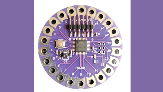
The LilyPad ATmega328P is a wearable board that is designed to be sewn onto clothing and other fabric surfaces. It is based on the Arduino platform and uses the same Atmel ATmega328P microcontroller as the Arduino Uno. The board has 14 digital I/O pins, 6 analog inputs, and can be powered by a 3.7V LiPo battery. It also has a built-in USB port for programming and debugging. The board is compatible with various LilyPad accessories, including sensors, LEDs, and buzzers.
Nano Board R3:

The Nano Board R3 is a compact and affordable board that is ideal for beginners and small projects. It has 22 digital I/O pins, 8 analog inputs, and can be powered via a USB cable or an external power source. The board runs on the Atmel ATmega328 microcontroller, which has a clock speed of 16 MHz. The Nano Board R3 has a built-in USB port for programming and debugging and is compatible with a range of shields and modules that can be used to expand its capabilities.
In conclusion, these three boards offer different features and capabilities, making them suitable for a wide range of applications. The Mega 2560 Pro is ideal for complex projects that require many I/O pins and high processing power. The LilyPad ATmega328P is perfect for wearable projects, while the Nano Board R3 is an excellent choice for beginners and small projects. Regardless of which board you choose, you can be sure that it will be compatible with the vast Arduino community and its extensive library of code and examples.
2 notes
·
View notes
Text
Buy Mega 2560 R3 Mega2560 REV3 (ATmega2560-16AU CH340G) Board ON USB Cable Compatible for Arduino With USB Cable
Buy Mega 2560 R3 Mega2560 REV3 (ATmega2560-16AU CH340G) Board ON USB Cable Compatible for Arduino With USB Cable
Mega 2560 R3 Mega2560 REV3 (ATmega2560-16AU CH340G) Board ON USB Cable Compatible for Arduino With USB Cable
Check Price

More Description
More photo
View On WordPress
0 notes
Text
Geekcreit® MEGA 2560 R3 ATmega2560 MEGA2560 Development Board With USB Cable Geekcreit for Arduino - products that work with official Arduino boards
Geekcreit® MEGA 2560 R3 ATmega2560 MEGA2560 Development Board With USB Cable Geekcreit for Arduino – products that work with official Arduino boards
Description: This is compatible R3 Mega2560 ATmega2560-16TW (upgrade version) control board with USB cable This is an ATmega2560 as core microcontroller development board itself has 54 groups digital I / O input / output terminal (14 groups do PWM outputs), 16 sets of simulation than the input side, group 4 UARTs (hardware serial ports), using the 16 MHz crystal oscillator. With the bootloader,…

View On WordPress
0 notes
Text
Arduino Mega 2560 with CH340 Driver and USB Cable
Arduino Mega 2560 with CH340 Driver and USB Cable
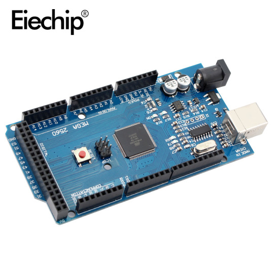
The ATmel MCU ATMEGA16U2 MEGA 2560 R3 Improved Version CH340G Board is a micro-controller board base on the ATmega2560. It has a USB host interface to connect with Android based phones, based on the MAX3421e IC. It has 54 digital input/output pins (of which 15 can be used as PWM outputs); 16 analog inputs, 4 UARTs (hardware serial ports), a 16 MHz crystal oscillator; a USB connection, a power…

View On WordPress
0 notes
Text

Arduino Mega 2560 R3 (Without Cable)
The Arduino Mega 2560 is an open-source microcontroller board based on ATmega2560. Along with this, it also has 54 digital I/O pins, 16 Analog Inputs, 4 UARTs, ICSP Header, 16 MHz Crystal Oscillator, a reset button, USB port, and a DC Power Jack. It is designed for projects which require more I/O lines, more sketch memory, and more RAM. It is best suited for Robotics, 3D printers, RC planes, etc. projects which require many sensors with different communication protocols and actuators to work in tandem. It gets programmed with the help of Arduino IDE and you do not need to attach any other components to program them. Its uses include in DIY projects, IoT based projects, Robotics, Prototyping for Electronic components and systems. The Arduino Microcontroller boards such as Arduino UNO, Arduino Nano, Arduino Leonardo, Arduino Pro Mini have revitalized the Automation Industry with their sheer simplicity and easy to use interface.
SPECIFICATIONS
The ATmega2560 is a Microcontroller
The operating voltage of this microcontroller is 5V
The recommended Input Voltage will range from 7V to 12V
The input voltage will range from 6V to 20V
The digital input/output pins are 54 where 15 of these pins will supply PWM o/p.
Analog Input Pins are 16
DC Current for each input/output pin is 40 mA
Flash Memory like 256 KB where 8 KB of flash memory is used with the help of bootloader
The Static Random Access Memory (SRAM) is 8 KB
The electrically erasable programmable read-only memory (EEPROM) is 4 KB
The clock (CLK) speed is 16 MHz
The USB host chip used in this is MAX3421E
The length of this board is 101.52 mm
The width of this board is 53.3 mm
Buy this Mega 2560: https://quartzcomponents.com/products/arduino-mega-2560-r3-without-cable
0 notes
Link
Feature: This board is completely solve the traditional 2560 board is not compatible with win7 and win8 system instability.Retains the main chip ATMEGA2560-16TW (Updated version) , replacing ...
0 notes
Text
Arduino.
Arduino adalah pengendali mikro single-board yang bersifat sumber terbuka, diturunkan dari Wiring platform, dirancang untuk memudahkan penggunaan elektronik dalam berbagai bidang. Perangkat kerasnya memiliki prosesor Atmel AVR dan softwarenya memiliki bahasa pemrograman sendiri.
Arduino juga merupakan senarai perangkat keras terbuka yang ditujukan kepada siapa saja yang ingin membuat purwarupa peralatan elektronik interaktif berdasarkan hardware dan software yang fleksibel dan mudah digunakan. Mikrokontroler diprogram menggunakan bahasa pemrograman arduino yang memiliki kemiripan syntax dengan bahasa pemrograman C. Karena sifatnya yang terbuka maka siapa saja dapat mengunduh skema hardware arduino dan membangunnya.
Arduino menggunakan keluarga mikrokontroler ATMega yang dirilis oleh Atmel sebagai basis, namun ada individu/perusahaan yang membuat clone arduino dengan menggunakan mikrokontroler lain dan tetap kompatibel dengan arduino pada level hardware. Untuk fleksibilitas, program dimasukkan melalui bootloader meskipun ada opsi untuk mem-bypass bootloader dan menggunakan pengunduh untuk memprogram mikrokontroler secara langsung melalui port ISP.
Jenis-Jenis Arduino
a. Arduino Uno
Jenis yang ini adalah yang paling banyak digunakan. Terutama untuk pemula sangat disarankan untuk menggunakan Arduino Uno. Banyak sekali referensi yang membahas Arduino Uno. Versi yang terakhir adalah Arduino Uno R3 (Revisi 3), menggunakan ATMEGA328 sebagai Microcontrollernya, memiliki 14 pin I/O digital dan 6 pin input analog. Untuk pemprograman cukup menggunakan koneksi USB type A to To type B. Sama seperti yang digunakan pada USB printer.
b. Arduino Due
Berbeda dengan saudaranya, Arduino Due tidak menggunakan ATMEGA, melainkan dengan chip yang lebih tinggi ARM Cortex CPU. Memiliki 54 I/O pin digital dan 12 pin input analog. Untuk pemprogramannya menggunakan Micro USB, terdapat pada beberapa handphone.
c. Arduino Mega
Mirip dengan Arduino Uno, sama-sama menggunakan USB type A to B untuk pemprogramannya. Tetapi Arduino Mega, menggunakan Chip yang lebih tinggi ATMEGA2560. Dan tentu saja untuk Pin I/O Digital dan pin input Analognya lebih banyak dari Uno.
d. Arduino Leonardo.
Bisa dibilang Leonardo adalah saudara kembar dari Uno. Dari mulai jumlah pin I/O digital dan pin input Analognya sama. Hanya pada Leonardo menggunakan Micro USB untuk pemprogramannya.
e. Arduino Fio
Bentuknya lebih unik, terutama untuk socketnya. Walau jumlah pin I/O digital dan input analognya sama dengan uno dan leonardo, tapi Fio memiliki Socket XBee. XBee membuat Fio dapat dipakai untuk keperluan projek yang berhubungan dengan wireless.
f. Arduino Lilypad
Bentuknya yang melingkar membuat Lilypad dapat dipakai untuk membuat projek unik. Seperti membuat amor iron man misalkan. Hanya versi lamanya menggunakan ATMEGA168, tapi masih cukup untuk membuat satu projek keren. Dengan 14 pin I/O digital, dan 6 pin input analognya.
g. Arduino Nano
Sepertinya namanya, Nano yang berukulan kecil dan sangat sederhana ini, menyimpan banyak fasilitas. Sudah dilengkapi dengan FTDI untuk pemograman lewat Micro USB. 14 Pin I/O Digital, dan 8 Pin input Analog (lebih banyak dari Uno). Dan ada yang menggunakan ATMEGA168, atau ATMEGA328.
h. Arduino Mini
Fasilitasnya sama dengan yang dimiliki Nano. Hanya tidak dilengkapi dengan Micro USB untuk pemograman. Dan ukurannya hanya 30 mm x 18 mm saja.
i. Arduino Micro
Ukurannya lebih panjang dari Nano dan Mini. Karena memang fasilitasnya lebih banyak yaitu; memiliki 20 pin I/O digital dan 12 pin input analog.
j. Arduino Ethernet
Ini arduino yang sudah dilengkapi dengan fasilitas ethernet. Membuat Arduino kamu dapat berhubungan melalui jaringan LAN pada komputer. Untuk fasilitas pada Pin I/O Digital dan Input Analognya sama dengan Uno.
k. Arduino Esplora
Rekomendasi bagi kamu yang mau membuat gadget sepeti Smartphone, karena sudah dilengkapi dengan Joystick, button, dan sebagainya. Kamu hanya perlu tambahkan LCD, untuk lebih mempercantik Esplora.
l. Arduino Robot
Ini adalah paket komplet dari Arduino yang sudah berbentuk robot. Sudah dilengkapi dengan LCD, Speaker, Roda, Sensor Infrared, dan semua yang kamu butuhkan untuk robot sudah ada pada Arduino ini.
Kelebihan Arduino.
1. Memiliki Bootloader Sendiri
2. Harga yang Terjangkau
3. Mudah Dipelajari
4. Menggunakan Port USB
5. Memiliki Banyak Library Gratis
Kekurangan Arduino
1.bahasa pemograman arduino
0 notes
Text
Geekcreit® MEGA 2560 R3 ATmega2560 MEGA2560 Development Board With USB Cable Geekcreit for Arduino - products that work with official Arduino boards
Geekcreit® MEGA 2560 R3 ATmega2560 MEGA2560 Development Board With USB Cable Geekcreit for Arduino – products that work with official Arduino boards
Description: This is compatible R3 Mega2560 ATmega2560-16TW (upgrade version) control board with USB cable This is an ATmega2560 as core microcontroller development board itself has 54 groups digital I / O input / output terminal (14 groups do PWM outputs), 16 sets of simulation than the input side, group 4 UARTs (hardware serial ports), using the 16 MHz crystal oscillator. With the bootloader,…

View On WordPress
0 notes
Text
Get Arduino Atmega 2560 R3 Board at Affordable Price in Ainow

With the MAX3421e IC, the Mega 2560 Atmega2560-16au compatible with Arduino is a microcontroller board based on the Arduino Atmega 2560 R3.
With a total of 54 digital input/output pins (including 15 PWM outputs), 16 analog inputs, and 4 UARTs, the MEGA ADK is jam-packed with features. It also boasts a 16 MHz crystal oscillator and comes equipped with a USB connection, power jack, ICSP header, and reset button. Based on the Arduino Atmega 2560 r3, this board shares many similarities with its counterparts, including the ATmega8U2 program that serves as a USB-to-serial converter. In fact, the Mega ADK revision 3 even includes a resistor that conveniently pulls the 8U2 HWB line to ground for easier DFU(Device Firmware Upgrade) mode access.
New features on the board include:
As part of the 1.0 pin-out, the shields will be able to adjust to the voltage provided by the board by adding SDA and SCL pins near the AREF pin and two new pins near the RESET pin, the IOREF. Shields in the future will be compatible with boards that use AVR, which operate at 5V, and Arduino Due, which operates at 3.3V. The second pin, which is not connected, will be used for future purposes.
Circuit with a stronger RESET.
A USB connection or an external power supply can be used to power the Arduino Atmega 2560 R3 Android Accessory Development Kit (ADK). An AC-to-DC adapter (wall-wart) or battery can be used to supply external (non-USB) power. An adapter can be connected by plugging a 2.1mm center-positive plug into the board’s power jack.
GND and Vin pin headers on the POWER connector can be inserted with battery leads. Since the Mega R3 Android Accessory Development Kit (ADK) is a USB Host, the phone will attempt to draw power from it when it needs to charge. When the ADK is powered over USB, 500mA is available for the phone and board.
Features and specifications:
Arduino Atmega 2560 r3 :
Atmel is the programmer
Microcontroller ATmega2560.
A total of 54 digital input/output terminals (14 of which have programmable PWM outputs) are available.
There are 16 analog inputs.
There are four UARTs (hardware serial ports).
A crystal clock with a frequency of -16 MHz.
A bootloader allows sketches to be downloaded via USB without having to go through an external writer.
-Powered by USB or external power supply (not supplied). The device will automatically switch between power sources.
A heavy gold plate construction is used.
The clock speed is 16 MHZ.
Bootloader uses 8 KB of the 256 KB flash memory.
The operating voltage is 6 x 12 volts.
Mega 2560 Arduino cable:
It is hot pluggable.
-Compatible with PCs.
Strain relief and PVC overmolding ensure error-free data transmissions for a lifetime.
-Aluminum under-mold shield helps meet FCC requirements for KMI/RFI interference.
-Filled and braided shield conforms to fully rated cable specifications and reduces EMI/FRI interference.
Error-free, high-performance transmission.
Case made of transparent acrylic:
MEGA2560 R3 (unassembled) compatible.
It is possible to adjust the cover.
Transparent color.
Acrylic is the material used.
The power of
The external power regulator has a maximum capacity of 1500mA. Of this, 750mA is reserved for the phone and MEGA ADK board, while the remaining 750mA is dedicated to any attached actuators and sensors. To use this amount of current, a power supply must be able to provide at least 1.5A. While the board can run on an external supply ranging from 5.5 to 16 volts, it is recommended to use between 7 and 12 volts. If supplied with less than 7V, there may be insufficient voltage output from the 5V pin, potentially causing instability in the board. On the other hand, using more than 12V may result in overheating of the voltage regulator and potential damage to the board components.
What follows is:
This pin is used to supply voltage to the Arduino board when it is powered by an external power source rather than 5 volts from the USB connection or another regulated source.
This pin generates a regulated 5V from the board’s regulator. The board can be powered via the DC power jack (7-12V), USB connector (5V), or VIN pin (7-12V). If you supply voltage via the 5V or 3.3V pins, you bypass the regulator and can damage your board. Please do not do so.
The onboard regulator generates 3.3 volts. Maximum current draw is 50 milliamps.
The ground pins are GND.
The Arduino board’s IOREF pin serves as a voltage reference for the microcontroller. In a properly configured shield, you can determine the voltage of the IOREF pin and select an appropriate power source or enable voltage translators to work with either 5V or 3.3V outputs.
The memory
It has 256 KB of flash memory for storing code (of which 8 KB is used for the bootloader), 8 KB of SRAM, and 4 KB of EEPROM (which can be read and written).
The inputs and outputs
By using pin Mode(), digital Write(), and digital Read() functions, each of the Arduino Atmega 2560 R3 Android Accessory Development Kit (ADK)’s 50 digital pins can be used as inputs or outputs. There is an internal pull-up resistor of 20-50 Ohm on each pin. They operate at 5 volts. They can provide or receive a maximum current of 40 mA. Some of the pins have specialized functions:
Serial 0: 0 (RX) and 1 (TX), Serial 1: 19 (RX) and 18 (TX), Serial 2: 17 (RX) and 16 (TX), Serial 3: 15 (RX) and 14 (TX). Connected to the ATmega8U2 USB-to-TTL Serial chip on pins 0 and 1.
External Interrupts: 2 (interrupt 0), 3 (interrupt 1), 18 (interrupt 5), 19 (interrupt 4), 20 (interrupt 3), and 21 (interrupt 2). An interrupt can be triggered on a low value, a rising or falling edge, or a change in value using the attach Interrupt() function.
Providing 8-bit PWM output with the analog Write() function for PWM values 2 to 13 and 44 to 46.
SPI: 50 (MISO), 51 (MOSI), 52 (SCK), 53 (SS). These pins support SPI communication using the SPI library. They are also broken out on the ICSP header, which is physically compatible with Uno, Duemilanove, and Diecimila.
MAX3421E is the USB host.
The Max3421E
The following pins are used to communicate with Arduino via the SPI bus:
Seven (RST), fifty (MISO), fifty one (MOSI), and fifty two (SCK) are digital.
You should not use Digital pin 7 for inputs or outputs because it is used to communicate with MAX3421E
PJ3 (GP_MAX), PJ6 (INT_MAX), PH7 (SS) are not broken out on headers.
A built-in LED is connected to digital pin 13. When the pin is HIGH, the LED is on, when it is LOW, it is off.
Supports TWI communication using the Wire library. These pins are not in the same location as the Duemilanove or Diecimila TWI pins.
Android Accessory Development Kit (ADK) with Arduino Atmega 2560 R3 has 16 analog inputs, each with a resolution of 10 bits (i.e. 1024 different values). It is possible to change the upper end of the range of the pins by using the AREF pin and analog Reference() function. Other pins on the board include:
Reference voltage for analog inputs. Use with analog reference.
Reset. This line is typically used to add a reset button to shields which block the board’s reset button.
The communication process
The Arduino Atmega 2560 R3 Android Accessory Development Kit (ADK) offers various communication options, including connecting with a computer, another Arduino, or other micro-controllers. The ATmega2560 has four hardware UARTs for TTL (5V) serial communication. Additionally, the board has an ATmega8U2 that uses USB to provide a virtual com port for computer software. For Windows machines, a .inf file may be needed but OSX and Linux machines will automatically detect the board as a COM port. In the Arduino software, there is a serial monitor feature for sending and receiving simple textual data from the board.
When data is transmitted via the ATmega8U2/16U2 chip and USB connection to the computer (but not for serial communication on pins 0 and 1), the board’s RX and TX LEDs flash. Any of the MEGA ADK’s digital pins can be serialized with a software-serial library. TWI and SPI communication are also supported by the ATmega2560. The Arduino software contains a Wire library to simplify TWI communication, see Wire library for details. For SPI communication, use the SPI library.
The USB host interface given by MAX3421E IC allows Arduino MEGA ADK to connect and interact with any type of device with a USB port. It allows you to interact with many types of phones, control Canon cameras, and interface with keyboards, mice, and gaming controllers such as Wiimote and PlayStation 3.
The programming language
For details, see the reference and tutorials. You can program the Mega R3 Android Accessory Development Kit (ADK) with Arduino software (download). You don’t need an external hardware programmer to upload new code to the ATmega2560 on the MEGA ADK since it comes preburned with a boot-loader (just like the Arduino Atmega 2560 r3). The STK500v2 protocol (references and C header files) is used for communication.
You can also bypass the bootloader and program the microcontroller through the ICSP (In-Circuit Serial Programming) header using Arduino ISP or similar; see these instructions for details. Atmega8U2 firmware source code is available in the Arduino repository. An ATmega8U2 is loaded with a DFU bootloader, which can be activated by:
The Rev1 boards have the following features:
Resetting the 8U2 requires connecting the solder jumper on the back of the board (near the map of Italy).
Rev2 and later boards have a resistor pulling the 8U2/16U2 HWB line to ground, making it easier to put into DFU mode. To load a new firmware, you can use the FLIP software (Windows) or the DFU programmer (Mac OS X and Linux). If you prefer, you can use the ISP header with an external programmer (overwriting the DFU bootloader). See this user-contributed tutorial for more information.
Reset (automatic) software
The Arduino Atmega 2560 r3 ADK has been designed to reset by software from a connected computer instead of requiring a physical press of the reset button before an upload. This is achieved by connecting one of the hardware flow control lines (DTR) of the ATmega8U2 to the reset line of the ATmega2560 through a 100 nano-farad capacitor. Whenever this line is asserted, causing it to drop low, the chip will be reset momentarily. The upload button in the Arduino environment makes use of this feature, enabling you to easily upload code without needing to manually press the reset button.
As a result, the boot-loader’s timeout can be reduced since DTR can be synchronized with the upload initiation. This arrangement also has additional effects when the MEGA ADK is linked to a computer running Mac OS X or Linux. Upon being connected to software via USB, the board resets and enters bootloader mode for about half a second. During this time, any non-code data will be disregarded by the programmed bootloader, but it will capture the first few bytes of data transmitted after the connection is established.
Ensure that the software your sketch is communicating with allows for a brief pause after establishing the connection before sending any initial data. The MEGA ADK has a trace that can be removed to disable the auto-reset function. Connect the pads on either side of the trace to re-enable it, labeled as RESET-EN. Alternatively, you can disable the auto-reset by connecting a 110-ohm resistor from 5V to the reset line; additional information can be found in this forum thread.
Over-current protection for USB devices
A resettable polyfuse protects your computer’s USB ports from shorts and overcurrents with the Arduino Atmega 2560 R3 Android Accessory Development Kit (ADK). In spite of the fact that most computers have their own internal protection, a fuse provides an additional layer of protection. When more than 500 mA is applied to the USB port, the fuse automatically stops the connection.
Shield compatibility and physical characteristics
The Mega R3 Android Accessory Development Kit (ADK) PCB has a maximum length and width of 4 inches and 2.1 inches respectively. The USB connector and power jack extend beyond the length, while three screw holes are available for surface or case attachment. It is important to note that the distance between digital pins 7 and 8 is 160 mil, which is not an even multiple of the standard 100 mil spacing for the other pins. Additionally, the MEGA ADK can be used with most shields designed for the Uno, Diecimila or Duemilanove boards.
The digital pins 0 to 13 (as well as the adjacent AREF and GND pins), analog inputs 0 to 5, the power header, and the ICSP header are all positioned in the same spot. In addition, the main UART (serial port) is located on the same pins (0 and 1); as are external interrupts 0 and 1 (pins 2 and 3). SPI is also available through the ICSP header on the MEGA ADK and Duemilanove / Diecimila.
On the MEGA ADK (20 and 21), I2C and D are not located on the same pins.
1 note
·
View note
Text
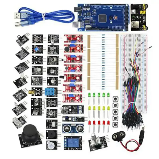
Stem Education for Arduino Mega Kit Atmega2560 MCU with Sensor Modules The Arduino Mega Kit electronic components packing list below: - 1 x KY-006 passive buzzer module - 1 x two colors module - 1 x Hit sensor module - 1 x Vibration switch module - 1 x Photo Resistance Module - 1 x Key switch module - 1 x Tilt switch module - 1 x 3-color full-color LED SMD modules - 1 x Infrared emission sensor module - 1 x 3-color LED module - 1 x Mercury open optical module - 1 x Yin Yi 2-color LED module 3 MM - 1 x active zoomer module - 1 x temperature sensor module - 1 x Automatic flashing colorful module - 1 x Mini reed magnetic modules - 1 x Hall magnetic sensor module - 1 x Infrared receiver sensor module - 1 x Class sensor magnetic Bihor - 1 x Magic Cup Light Module - 1 x encoder module - 1 x Broken Optical Module - 1 x Heartbeat Detection Module - 1 x Reed module - 1 x Obstacle avoidance sensor module - 1 x sensor module - 1 x Microphone sound sensor module - 1 x Laser sensor module - 1x5 V relay module - 1 x temperature sensor module - 1 x temperature sensor module - 1 x Linear Magnetic Salon Sensors - 1 x Flame sensor module - 1 x Sensitive Microphone Sensor Module - 1 x Temperature and humidity sensor module - 1 x XY-like joystick module - 1 x Metal Touch Sensor Module - 1x Development Board for Arduino Mega 2560 R3 - 1 x SR04 - 1 x MB-102 - 1x9v battery buckle - 1 x Bread plate electric source - 6x1 K - 6x10 K - 6x100 K - 6 x 220R - 5 x keys - 4 x LED yellow 5mm - 4 x LED Red 5mm - 4 x LED Green 5mm The atmega2560 mcu development board for arduino mega kit comes with exact parts list as piture show online. Note:We only provide hardware.Turtial or lesson is not provided,they are universal use everywhere from the internet. Other development kits,view here. If you are STEM education user,welcome contact us to talk the customzied hardware list. About Us: Shenzhen Chengsuchuang Technology Co.,Ltd. provide one stop supply solution to Arduino development board kits,including arduino uno,mega,nano etc.All of our products warranty is 1 year warranty default.We are in the electronics hardware since 2014. Read the full article
0 notes
Text
Choosing the Perfect Arduino Board for Your Project: Exploring MEGA 2560, Uno R3, and 3.3V Pro Mini
Arduino is an open-source electronics platform that has revolutionized the way we interact with the world around us. Arduino boards come in different shapes and sizes, each with unique features and capabilities. In this blog, we will discuss three different types of Arduino-compatible boards: MEGA 2560 R3 Board, Uno R3 CH340G Development Board with Micro USB port, and 3.3V 8M Pro Mini ATMEGA328P board.
MEGA 2560 R3 Board:

The MEGA 2560 R3 Board is an advanced Arduino board that is compatible with most shields designed for the Arduino Duemilanove and Diecimila boards. It is equipped with an Atmel ATmega2560 microcontroller and has 54 digital I/O pins, 16 analog inputs, and 4 UARTs (hardware serial ports). This board is ideal for projects that require a large number of inputs and outputs, such as robotics or automation projects. The MEGA 2560 R3 Board also has a USB interface that allows it to be connected to a computer for programming and debugging.
Uno R3 CH340G Development Board with Micro USB port:
The Uno R3 CH340G Development Board with Micro USB port is a compact and easy-to-use Arduino board. It features an Atmel ATmega328P microcontroller and has 14 digital I/O pins, 6 analog inputs, and 1 UART (hardware serial port). This board is great for beginners and hobbyists who want to learn and experiment with electronics and programming. The Uno R3 CH340G Development Board also has a micro USB port, which allows it to be easily connected to a computer for programming and power.
3.3V 8M Pro Mini ATMEGA328P board:

The 3.3V 8M Pro Mini ATMEGA328P board is a low-power and low-cost Arduino board. It features an Atmel ATmega328P microcontroller and has 14 digital I/O pins, 6 analog inputs, and 1 UART (hardware serial port). This board is ideal for projects that require low power consumption, such as battery-powered devices or remote sensors. The 3.3V 8M Pro Mini ATMEGA328P board is also very small and can be easily embedded into projects.
Conclusion
Arduino boards come in different shapes and sizes, each with unique features and capabilities. The MEGA 2560 R3 Board is ideal for projects that require a large number of inputs and outputs, the Uno R3 CH340G Development Board is great for beginners and hobbyists, and the 3.3V 8M Pro Mini ATMEGA328P board is ideal for low-power and small projects. Whatever your project may be, there is an Arduino-compatible board that will fit your needs.
0 notes
Photo
MEGA2560 Mega 2560 R3 REV3 ATmega2560-16AU CH340G AVR Board ON USB Cable Compatible For arduino Mega 2560 R3 Development Board (Discount 15 % ) #MEGA2560 #Mega #2560 https://bit.ly/2AVZy2e
0 notes
Photo

MEGA2560 Mega 2560 R3 REV3 ATmega2560-16AU CH340G AVR Board ON USB Cable Compatible For arduino Mega 2560 R3 Development Board (Discount 15 % ) #MEGA2560 #Mega #2560 https://bit.ly/38U6PMJ
0 notes
Text
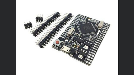
Microcontroller Arduino Mega 2560 Pro

In diesem Beitrag möchte ich dir den Arduino Mega 2560 Pro vorstellen. Dieser Microcontroller ist der kleine Bruder des Arduino Mega 2560 R3 welchen ich dir bereits im gleichnamigen Beitrag Arduino MEGA 2560 R3 – Übersicht vorgestellt habe und wird oft auch mit dem Zusatz "mini" vertrieben.
Bezug des Mega 2560 Pro
Den Microcontroller habe ich über ebay.de für knapp 7€ inkl. Versandkosten erstanden. Wenn du etwas mehr sparen möchtest so würde ich dir einen Blick zu aliexpress.com, banggood.com oder wish.com empfehlen dort findest du den Mega 2560 Pro noch günstiger (jedoch meist mit längeren Lieferzeiten). Solltest du nicht so lange auf deinen Microcontroller warten wollen so findest du diesen auch auf amazon.de, jedoch zu einem deutlich höheren Preis (meist mehr als das doppelte). Lieferumfang Zum Lieferumfang des Mega 2560 Pro gehören lediglich die Stiftleisten welche an den Microcontroller angelötet werden. Da das Board beidseitig beschriftet ist können diese Stiftleisten sowohl auf der Vorder- oder auf der Rückseite angelötet werden.
Vergleich Mega 2560 Pro & Arduino Mega 2560 R3
Der Arduino Mega 2560 Pro und der große Mega 2560 R3 besitzen den gleichen CPU somit sind sehr viele Eigenschaften der Boards identisch.

Arduino Mega 2560 R3 & Arduino Mega 2560 Pro Auf dem Bild kann man den Größenunterschied der beiden Microcontroller deutlich erkennen. Arduino Mega 2560 Pro Arduino Mega 2560 R3 CPU Typ ATMEGA2560-16AU CPU - Takt 16 MHz USB-UART Converter CH340G Speicher Flash 256 KB (8 KB für den Bootloader reserviert) SRAM 8 KB EEPROM 4 KB digitale / analoger Pins analoge Pins 16 digitale Pins 54 (davon 15 PWM) Betriebsspannung Vout 5V 800 mA 200 mA 3.3V 800 mA 50 mA Vin 7V bis 9V (max. 18V) 7V bis 12V (max. 20V) Stromverbrauch 200 mA keine Angaben Schnittstelle USB Micro USB Typ B Stromversorgung 9V Jack Adapter, 2,1mm Hohlstecker kein separater Anschluß vorhanden Abmaße L x B x H 52 mm x 38 mm x 15 mm 150 mm x 54 mm x 16 mm Wenn man auf die Technischen Daten des Mega 2560 Pro (mini) schaut, erkennt man sehr viele Gemeinsamkeiten mit dem großen Arduino Mega 2560 R3. Einzig die doppelreihige Stiftleiste ist schon etwas seltsam denn mit dieser hat man die Möglichkeit verbaut den Microcontroller auf ein Breadboard zu stecken.

Mega 2560 Pro mini größenvergleich mit einer 50 Cent Münze Im Onlineshop aliexpress.com gibt es auch ein Prototype Board mit welchem man die Pins etwas bequemer abgreifen kann, jedoch könnte man dann gleich zum großen Bruder greifen. Der Microcontroller verfügt über einen "normalen" Chip und hat abgesehen von den geringen Abmaßen keinerlei Besonderheiten gegenüber einem anderen Microcontroller. Es gestaltet sich also etwas schwierig ein Projekt speziell für den Mega 2560 Pro zu finden. Daher werde ich in meinen nächsten Projekten zu Sensoren & Aktoren für die Arduino Familie diesen kleinen Microcontroller verwenden. Read the full article
0 notes