#capacitive level sensor
Explore tagged Tumblr posts
Visit Tumblr Blog
Explore Tumblr blogs with no restrictions, modern design and the best experience.
Last Seen Tumblr Blogs


Fun Fact
Tumblr is used by 21% of adults online aged 18-29 years.
Text
Proximity Sensors: Enhancing Efficiency and Safety Across Industries
What are Proximity Sensors
Proximity sensors identify an object's presence even in the absence of physical touch. Without coming into direct touch with the item, they are made to recognize when it enters the sensor field. In a variety of manufacturing applications, proximity sensors are used to identify the proximity of metallic and non-metallic items.
How Do Proximity Sensors Function?
In the least complex terms, proximity sensors work by communicating information about the presence or movement of an item into an electrical sign. They yield an ON signal when the article enters their reach. There are a few critical contrasts in the manner that different closeness sensors work, as made sense below:
Capacitive Nearness Sensor Working Guideline Capacitive
Proximity sensors work by identifying changes in capacitance between the sensor and an item. Factors, for example, distance and the size of the article will influence how much capacitance. The sensor just recognizes any progressions in the limit produced between the two.
Inductive Nearness Sensor Working Standard
Inductive sensors work by recognizing vortex flows causing attractive misfortune, created by outer attractive fields on a conductive surface. The discovery curl produces an air conditioner attractive field, and impedance changes are distinguished because of the created whirlpool flows.
Attractive Vicinity Switches Working Rule Attractive
Proximity switches are similarly basic and clear. The reed end of the switch is worked by a magnet. At the point when the reed switch is enacted and ON, the sensor additionally turns ON.
It is additionally significant that proximity sensors are not impacted by the surface shade of the article identified. They depend simply on actual development and the movement of an item, so its tone doesn't assume a part in that frame of mind of the sensor.
The Role of Proximity Sensors in Modern Industries
Sensors have become indispensable in today's automated world, serving important functions such as tracking and positioning control. In this field, location and proximity sensors are reshaping several industries. By detecting nearby vehicles in the automotive industry and accurately tracking the location of delivered packages in production, these sensors show their versatility and potential in several fields.
Robotics
Both position and proximity sensors are used in many applications in the field of robotics. For example, linear position sensors are commonly used in robotics and industrial settings for object detection, part fixation, and machine control. These sensors play an essential role in detecting the location, distance, and proximity of moving objects and provide important information for robot navigation and manipulation.
Industrial Automation
Today many manufacturers use these sensors to improve work productivity and efficiency. Integrating position and proximity sensors into production systems enables accurate detection and tracking of objects on conveyor belts, robotic arms, and assembly lines. This combination enables precise object positioning and motion control in industrial processes.
Security systems
Combining proximity and location sensors, security systems can be used to track and control the movement of objects in a certain area. It is useful in surveillance, burglar alarms, and access control systems.
Automotive Applications
The combination of these position and proximity sensors can be used in parking systems to detect open spaces and nearby cars in a parking lot, and accurately track the location of a vehicle for parking assistance. These sensors are also used to improve the safety and performance of Advanced Driver Assistance Systems (ADAS) vehicles.
Smart Healthcare
Location and proximity sensors play a vital role in healthcare, facilitating the monitoring and management of various aspects of medical facilities. Wearable proximity sensors play an important role in both acute and chronic health conditions, as they allow non-contact detection and monitoring of physical movements and interactions.
Food and Beverage Industry
A proximity sensor for food is a type of sensor that is designed specifically for use in the food industry. It is used to detect the presence or absence of food items during various stages of food processing, packaging, and handling.
As technology advances, the integration of location and proximity sensors is expected to increase security, automation, and sensor innovation. based systems in various industries.
#proximity sensors#inductive proximity sensor#proximity sensor types#inductive sensor#what is proximity sensor#proximity sensor price#proximity sensor working#working of proximity sensor#omron proximity sensor#sensors working principle#magnetic proximity sensor#optical proximity sensor#proximity switch sensor#inductive sensor working principle#an inductive proximity sensor comprises#autonics proximity sensor#features of sensors#proximity sensor definition#proximity switch function#capacitive sensor#capacitive proximity sensor#capacitive level sensor#capacitive sensor working
0 notes
Text
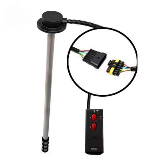
The working theory of the capacitance level sensor(CLS) uses capacitance that is created by liquid that fill in the positive and negative probe. With the change of the liquid level, the change of the capacitance will be converted to standard electrical output signal. The main component is the highly-integrated capacitance chips, by the exact temperature compensation and linear correction, the sensor has the advantage of high accuracy, high stability and continuous measurement.
4 notes
·
View notes
Text
Genset Electronic Controller and Sensors provider
UNI-TECH Automation Pvt. Ltd specializes in providing high-quality Genset Electronic Controller & Sensors, ensuring reliable performance and efficiency for your power generation needs.

#UL & CSA approved Cables India#Control Panel Suppliers Pune#Wiring harness manufacturer Pune#Sheet metal fabrication & Powder coating#Genset Electronic Controller & Sensors#Capacitive Fuel level sensors
0 notes
Text
Unitech: Genset Electronic Controller & Sensors provider
UNI-TECH Automation Pvt. Ltd specializes in providing high-quality Genset Electronic Controller & Sensors, ensuring reliable performance and efficiency for your power generation needs.

#UL & CSA approved Cables India#Control Panel Suppliers Pune#Wiring harness manufacturer Pune#Sheet metal fabrication & Powder coating#Genset Electronic Controller & Sensors#Capacitive Fuel level sensors
0 notes
Text

Green Thumb Trinkey springs into existence 🌱💧🌞
With recent work to improve our soil moisture sensing, it could be a nice time to design an 'all-in-one' board for plant and garden hacking. This board has a USB C, so you can plug it right into your computer and read the capacitance of the soil, as well as the ambient light level and temperature + humidity of the onboard AHT20. A QT sensor and 'standard Stemma QT' mounting holes mean you can plug in a VOC, CO2, UV, or PM.2 sensor. The SAMD21E18 can run Arduino or CircuitPython, but we'll also ship it with an example that just spits out CSV data over the serial port for instant interfacing. Coming soon.
#adafruit#trinkey#arduino#circuitpython#SAMD21E18#gardentech#plantcare#soilmoisture#smartgardening#usbctools#diygardening#sensorboard#plantmonitor#techforplants#hardwarehacking
6 notes
·
View notes
Text
SG-845 Digital Hygrometer | Humidity & Temperature
A SG-845 Digital Hygrometer with Comfort Humidity & Temperature is a gadget utilized to degree and show the relative mugginess (RH) level in the discuss you can discover cheapest cost in BD. Moreover, relative mugginess is a degree of the sum of dampness or water vapor show in the discuss compared to the most extreme sum it can hold at a given temperature. It is communicated as a percentage.
How SG-845 Digital Hygrometer is Utilized for Humidity & Temperature
Firstly, Digital hygrometer utilize electronic sensors to degree stickiness and show the comes about on a computerized screen, frequently in numerical shape. Besides, this electronic estimation and show strategy earned them the title “digital.” These sensors utilize different innovations like capacitive or resistive sensors to distinguish stickiness changes with precision.
Secondly, Digital hygrometer are commonly utilized in different applications. It makes a difference property holders and HVAC experts screen indoor mugginess levels to guarantee consolation and anticipate form development or over the top dryness. Another, fabricating forms, capacity offices, and research facilities utilize these hygrometers to control stickiness for item quality and security.
Additionally, exact mugginess control is basic to protect profitable craftsmanship, chronicled artifacts, and touchy records. Besides, ranchers and horticulturists utilize hygrometers to oversee mugginess levels in nurseries for ideal plant development. Hence, meteorologists utilize hygrometers as portion of climate stations to degree and track stickiness, which is vital for climate forecasting.
In This Digital hygrometer are regularly more exact and simpler to studied than conventional analog hygrometers, which utilize a pointer and a scale to show mugginess levels. On the other hand, they come in different sizes and plans, from versatile handheld models to bigger settled units.

2 notes
·
View notes
Text
iPhone 16 news

The upcoming iPhone 16 lineup, expected in September 2024, could bring several new features and improvements, both in design and internal specifications. Here’s a comprehensive look at what the rumors suggest for the iPhone 16 series:
1. New Processor: A18 Pro
The iPhone 16 Pro and Pro Max models are expected to be powered by the new A18 Pro processor, which is said to offer modest speed improvements and a significantly enhanced Neural Engine, designed to support Apple's AI efforts under the brand "Apple Intelligence." This new chip will continue to be based on the 3nm process, further optimizing power efficiency and performance. Meanwhile, standard models might receive a variant of the A18 to support some level of Apple Intelligence.
2. Capture Button for Pro Models
One of the standout features rumored for the iPhone 16 Pro models is the addition of a new "Capture button," which is expected to be located below the sleep/wake button. This button could function similarly to a shutter button on a digital camera, offering multiple functionalities like half-press to focus, press to capture, and swipe for zoom control. It could be capacitive or mechanical, with haptic feedback provided by two Taptic Engine motors.
3. Camera Upgrades: 48MP Ultra-Wide and Vertical Alignment
The iPhone 16 Pro models are rumored to feature a 48MP Ultra-Wide camera, enhancing the capabilities of the 0.5x and macro modes. This sensor upgrade could also improve spatial video capture and Portrait mode. Additionally, the base models may return to a vertical camera alignment, which was last seen in the iPhone 12, to enable 3D video recording for Apple Vision Pro.
2 notes
·
View notes
Text
How to Do a Load Bank Test on a Generator?|EMAX Load Bank
Generators are critical assets for businesses and homes, providing essential backup power during outages. To ensure that a generator will perform as needed during an emergency, it is crucial to conduct regular maintenance and testing. One of the most effective ways to test a generator's performance is through a load bank test. This comprehensive guide will walk you through the steps of performing a load bank test on a generator, ensuring optimal performance and reliability.

What is a Load Bank Test?
A load bank test involves using a device known as a load bank to simulate electrical loads that the generator might encounter during operation. The test ensures the generator can handle its full rated capacity and helps identify any issues that could affect performance. Load bank tests are essential for maintaining the health of standby generators, ensuring they can provide reliable power when needed.

Why Perform a Load Bank Test?
Performing a load bank test has several benefits:
Verification of Performance: Ensures the generator can handle its maximum load without issues.
Identifying Potential Problems: Helps detect issues like wet stacking in diesel generators, which occurs when the engine doesn't reach optimal temperature.
Improved Reliability: Regular testing ensures the generator is reliable and ready for emergencies.
Compliance with Regulations: Some industries require regular load testing to comply with safety and operational regulations.

Types of Load Bank Tests
There are three primary types of load bank tests:
Resistive Load Bank Test: Simulates real-world loads such as lighting and heating. It is the most common type of test.
Reactive Load Bank Test: Simulates loads that include inductive (motors, transformers) and capacitive (capacitors) components.
Combined Load Bank Test: Uses both resistive and reactive loads to simulate the most realistic operating conditions.

Preparation for Load Bank Testing
Before performing a load bank test, follow these preparatory steps:
1. Review Manufacturer Guidelines
Consult the generator’s manual for specific instructions and safety precautions related to load bank testing. Adhering to manufacturer guidelines is crucial to avoid voiding warranties or causing damage.
2. Inspect the Generator
Conduct a thorough visual inspection of the generator. Look for any signs of wear, leaks, or damage. Ensure that the fuel, oil, and coolant levels are adequate and that all connections are secure.
3. Ensure Adequate Ventilation
Load testing generates a significant amount of heat. Ensure that the testing area is well-ventilated to dissipate heat and prevent overheating.
4. Gather Necessary Equipment
Ensure you have the following equipment ready:
Load bank unit
Load cables
Personal protective equipment (PPE)
Monitoring devices (e.g., multimeters, temperature sensors)

Step-by-Step Guide to Performing a Load Bank Test
Step 1: Connect the Load Bank to the Generator
Safety First: Wear appropriate PPE, including gloves and safety glasses.
Shut Down the Generator: Ensure the generator is turned off before making any connections.
Connect Cables: Attach the load bank cables to the generator’s output terminals. Ensure that the connections are secure to prevent arcing or loose connections.
Verify Connections: Double-check all connections to ensure they are tight and correctly aligned.
Step 2: Start the Generator
Start-Up: Follow the standard procedure to start the generator.
Warm-Up Period: Allow the generator to run for a few minutes to reach its normal operating temperature. This helps in accurate load testing.
Step 3: Gradually Apply Load
Incremental Load: Begin by applying a small load incrementally using the load bank. This gradual increase helps prevent sudden surges that could damage the generator.
Monitor Parameters: As you increase the load, continuously monitor the generator’s parameters, such as voltage, current, frequency, and temperature.
Stabilize Each Load Level: Allow the generator to stabilize at each load level for a few minutes. This helps in identifying any potential issues early.
Step 4: Apply Full Load
Full Load Application: Once the generator has stabilized at incremental loads, apply the full rated load. This step is crucial as it tests the generator’s ability to handle its maximum capacity.
Continuous Monitoring: Keep monitoring all critical parameters. Look for any signs of overheating, abnormal vibrations, or unusual noises.
Step 5: Maintain Full Load
Duration: Maintain the full load for a specified duration, typically around 30 minutes to an hour. This duration helps in identifying any long-term issues.
Document Readings: Record all readings and observations during the test. This documentation is valuable for future reference and maintenance planning.
Step 6: Gradually Reduce Load
Incremental Reduction: Gradually reduce the load in small increments until the generator is running without any load.
Cooldown Period: Allow the generator to run without load for a few minutes to cool down gradually.
Step 7: Shut Down and Disconnect
Shutdown Procedure: Follow the standard shutdown procedure for the generator.
Disconnect Cables: Safely disconnect the load bank cables from the generator. Ensure that all connections are secure and the generator is back to its standby mode.

Post-Test Analysis and Maintenance
Review Test Data
Analyze the data collected during the test. Look for any anomalies or deviations from normal operating parameters. Identifying trends or issues early can prevent major problems later.
Inspect Generator
Conduct a post-test inspection of the generator. Look for any signs of stress or damage caused by the load test. Check for leaks, unusual wear, or any other abnormalities.
Perform Necessary Maintenance
Based on the test results and inspection, perform any necessary maintenance. This may include changing filters, topping off fluids, tightening connections, or addressing any identified issues.
Update Maintenance Records
Keep detailed records of the load bank test, including all readings, observations, and maintenance actions taken. This information is crucial for tracking the generator’s performance over time and planning future maintenance.

Safety Considerations
Safety is paramount when performing a load bank test. Here are some key safety considerations:
Follow Manufacturer Guidelines: Always adhere to the generator and load bank manufacturer’s safety instructions.
Use PPE: Wear appropriate personal protective equipment, such as gloves, safety glasses, and hearing protection.
Secure Connections: Ensure all electrical connections are secure and correctly made to prevent electrical hazards.
Monitor Continuously: Never leave the generator unattended during the test. Continuous monitoring is essential to identify and address issues promptly.
Adequate Ventilation: Ensure the testing area is well-ventilated to dissipate heat generated during the test.
Conclusion
A load bank test is an essential part of generator maintenance, ensuring that your generator is capable of handling its full rated capacity and ready to provide reliable backup power during emergencies. By following the steps outlined in this guide, you can perform a load bank test safely and effectively. Regular testing, combined with routine maintenance, will help extend the life of your generator and ensure its reliability when you need it most.
Maintaining detailed records of each load bank test, addressing any identified issues promptly, and adhering to safety protocols will contribute to the long-term performance and reliability of your generator. By investing time and effort into regular load bank testing, you can have peace of mind knowing that your generator is ready to perform at its best when it matters most.
2 notes
·
View notes
Text
Top Benefits of Using Capacitive Fuel Level Sensors in Fleets
Fuel management is a critical aspect of fleet operations, directly impacting efficiency, cost control, and overall performance. With fuel prices fluctuating and operational costs on the rise, accurate and reliable fuel monitoring has never been more essential. This is where Capacitive Fuel Level Sensors come into play. These advanced sensors are becoming the preferred choice for fleet managers who want to optimize fuel usage, prevent pilferage, and improve accountability. In this blog, we explore the top benefits of using Capacitive Fuel Level Sensors in fleets, with a focus on solutions provided by Indication Instruments.

What Are Capacitive Fuel Level Sensors?
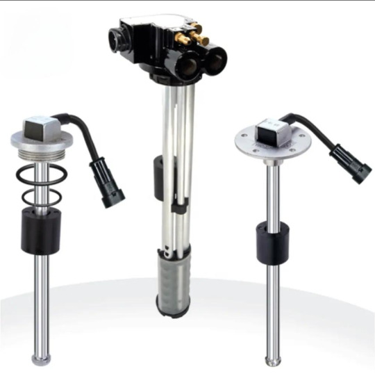
Capacitive Fuel Level Sensors are electronic devices used to measure the level of fuel in a tank using the principle of capacitance. Unlike traditional float-based sensors, which rely on mechanical movement, capacitive sensors detect fuel levels based on changes in electrical capacitance caused by the presence of fuel.
These sensors offer high precision and reliability, even in harsh environmental conditions, making them ideal for commercial fleets, trucks, buses, construction equipment, and more.
1. High Accuracy and Reliability
One of the primary benefits of Capacitive Fuel Level Sensors is their high accuracy. These sensors can detect even minute changes in fuel levels, providing real-time data that helps fleet managers track usage more effectively. Since there are no moving parts, the chances of mechanical failure are significantly reduced.
With solutions from Indication Instruments, fleet operators can expect consistent performance, whether the vehicles are operating in hot deserts, cold mountains, or humid environments.
2. Real-Time Fuel Monitoring
Capacitive Fuel Level Sensors support real-time monitoring of fuel levels. When integrated with telematics systems, they provide live updates on fuel usage, refueling events, and sudden drops that could indicate leakage or theft.
This real-time data allows managers to respond proactively to anomalies, ensuring better control over fleet operations. Indication Instruments offers sensors compatible with various GPS and fleet management systems, ensuring seamless integration.
3. Fuel Theft Prevention
Fuel theft is a significant concern for fleet operators, especially in remote areas or during overnight stops. Capacitive Fuel Level Sensors can instantly detect unauthorized fuel drainage by identifying abrupt fuel level drops.
By receiving immediate alerts, fleet managers can investigate and act swiftly to prevent further losses. Over time, this can lead to substantial savings and enhanced operational security.
4. Enhanced Fuel Efficiency
Understanding fuel consumption patterns is key to improving efficiency. Capacitive sensors help track how much fuel is being used per trip, per route, or per driver. This information can be used to train drivers, optimize routes, and reduce idling time.
By using data from Indication Instruments’ sensors, fleets can implement data-driven strategies to cut fuel waste and improve overall fuel economy.
5. Durability in Harsh Conditions
Fleet vehicles often operate in challenging environments — extreme temperatures, dust, vibration, and exposure to moisture. Capacitive Fuel Level Sensors are designed to withstand these conditions.
The robust build and corrosion-resistant materials used in Indication Instruments’ sensors ensure long service life with minimal maintenance, making them a cost-effective solution for long-term operations.
6. Ease of Installation and Calibration
Modern Capacitive Fuel Level Sensors are designed for straightforward installation. Many models from Indication Instruments offer flexible configurations to match various tank shapes and sizes. Calibration can also be done digitally, reducing downtime and ensuring accurate readings from day one.
This ease of setup is a significant advantage for fleet managers looking to implement a large number of sensors without disrupting operations.
7. Data-Driven Decision Making
Capacitive Fuel Level Sensors provide detailed insights into fuel usage, helping management make informed decisions. Whether it’s identifying underperforming vehicles, inefficient routes, or drivers with high consumption rates, the data empowers better planning and resource allocation.
With the analytics support from Indication Instruments, fleet managers can visualize trends and take corrective actions proactively.
8. Reduced Maintenance Costs
Traditional float-based sensors are prone to wear and tear, requiring frequent maintenance or replacement. Capacitive sensors, on the other hand, are solid-state devices with no mechanical parts, resulting in lower maintenance costs over time.
Choosing a trusted brand like Indication Instruments means you benefit from high-quality components, reducing the need for frequent service interventions.
9. Customizable and Scalable Solutions
Every fleet has unique needs based on vehicle types, fuel tank designs, and operational environments. Indication Instruments offers customizable Capacitive Fuel Level Sensors that can be tailored to fit specific requirements.
As your fleet grows, these systems are scalable, allowing easy expansion without overhauling the existing setup.
10. Environmental Benefits
Accurate fuel monitoring helps reduce unnecessary fuel consumption and associated emissions. By improving fuel efficiency and minimizing wastage, fleets contribute to a lower carbon footprint.
Indication Instruments supports eco-friendly fleet management through smart sensing solutions, helping businesses align with sustainability goals.
Why Choose Indication Instruments?
With years of experience in sensor technology, Indication Instruments is a trusted name in the field of fuel monitoring systems. Their Capacitive Fuel Level Sensors are engineered with precision, reliability, and compatibility in mind.
Key advantages of choosing Indication Instruments:
Proven track record across industries
High-accuracy sensing technology
Compatibility with popular telematics platforms
Customizable solutions for various tank types
Responsive customer support and technical assistance
Whether you manage a logistics fleet, construction vehicles, or public transportation, Indication Instruments delivers dependable fuel level monitoring solutions that drive efficiency and accountability.
Conclusion
Investing in Capacitive Fuel Level Sensors is a smart move for any fleet-focused business aiming to cut fuel costs, prevent theft, and enhance operational visibility. With accurate data, durable design, and seamless integration, these sensors have become an essential tool for modern fleet management.
Indication Instruments stands at the forefront of this technological advancement, offering fleet operators the tools they need to stay competitive, efficient, and secure. Make the switch today and take control of your fuel management like never before.
0 notes
Text
Understanding the Role of Hollow Shaft Rotary Encoders in Modern Robotics
Introduction to Rotary Encoders in Robotics
Rotary encoders are fundamental components in robotic systems, serving as critical feedback devices that measure the rotation, position, and direction of motor shafts. These sensors translate mechanical motion into electrical signals, which control systems then interpret to ensure precise movement. Among the various types of rotary encoders, hollow shaft rotary encoders have emerged as a key player due to their compact design, ease of integration, and high reliability. As robotics continues to permeate sectors like manufacturing, healthcare, logistics, and consumer electronics, understanding the specific contributions of hollow shaft rotary encoders becomes vital. Their importance lies not only in their functional capabilities but also in how they influence design flexibility and performance optimization in robotic applications. By integrating seamlessly into existing architectures, these encoders reduce mechanical complexity while improving feedback accuracy. This comprehensive examination will explore how these components are revolutionizing modern robotics, from their design advantages to their roles in various robotic subsystems.
Evolution of Rotary Encoders and Robotic Needs
The development of rotary encoders parallels the evolution of robotics itself. Early robotic systems relied on open-loop controls, often leading to inaccuracies and inefficiencies. As the demand for precision and repeatability grew, rotary encoders became indispensable. Initially, these sensors were bulky and susceptible to environmental interference. Over time, however, innovations in materials, signal processing, and miniaturization led to more robust and compact designs. Hollow shaft rotary encoders, in particular, emerged as a response to the need for space-saving yet highly accurate feedback devices. Robotics has evolved from simple pick-and-place machines to complex, autonomous entities requiring precise coordination across multiple axes. This shift necessitated encoders capable of delivering consistent, high-resolution feedback without contributing to design bulk. In mobile robots, surgical devices, and industrial arms, space is a premium commodity. Hollow shaft encoders allow engineers to route cables or mechanical shafts through the encoder's center, optimizing spatial configuration and reducing wear on moving parts. This evolution marks a significant turning point in the interplay between sensor technology and robotic capability.
Anatomy of a Hollow Shaft Rotary Encoder
At its core, a hollow shaft rotary encoder consists of a rotor, stator, and signal processing circuitry housed in a compact unit. What distinguishes it from other encoder types is the central hollow section through which a shaft or cabling can pass. This seemingly simple design offers substantial advantages. The rotor attaches directly to the rotating shaft, while the stator remains fixed to the structure. As the shaft turns, the encoder senses the angular displacement and transmits corresponding electrical signals. These signals may be digital or analog, depending on the encoder type and application. Typically, hollow shaft encoders utilize optical, magnetic, or capacitive technologies to detect movement. Optical encoders, for instance, use a light source and a photo-detector array to interpret interruptions in a coded disc. This method provides high-resolution data, essential for robotic operations requiring micrometer-level precision. Additionally, many hollow shaft encoders incorporate features like integrated bearings, multi-turn tracking, and error correction protocols, ensuring they maintain accuracy even under high-speed or high-vibration conditions.
Integration in Robotic Joint Systems
One of the primary applications of hollow shaft rotary encoders in robotics is within joint systems. Whether in humanoid robots or articulated industrial arms, joint movement must be monitored and controlled with utmost precision. Hollow shaft encoders facilitate this by being mounted directly onto the joint actuators, enabling real-time position feedback. Their hollow design allows power and data cables to pass through the joint axis, reducing external cabling and potential points of failure. This configuration not only enhances the mechanical efficiency of the joint but also simplifies maintenance and design. In collaborative robots, or cobots, where safety and fluid motion are paramount, these encoders help ensure smooth articulation and responsive behavior. They support closed-loop control systems that adjust motor output dynamically based on encoder feedback. This loop is crucial for tasks like pick-and-place operations, precision welding, or surgical manipulations, where even millimeter-level deviations can compromise functionality or safety. By offering a balance of compactness, accuracy, and reliability, hollow shaft rotary encoders are central to robotic articulation systems.
Enhancing Mobility in Autonomous Robots
Autonomous mobile robots (AMRs) require robust sensory systems to navigate complex environments accurately. Hollow shaft rotary encoders play an essential role in this context by providing reliable feedback on wheel or track rotation. Unlike incremental encoders that only track changes in position, absolute feedback systems offer the advantage of positional memory. This becomes crucial in navigation, where knowing the robot's exact orientation at any given time determines path planning and obstacle avoidance efficacy. In differential drive systems, for instance, encoders mounted on each wheel shaft measure relative speeds and directions, allowing for accurate steering and speed control. The compact nature of hollow shaft encoders is especially beneficial in mobile platforms, where every millimeter of space impacts battery size, payload capacity, or sensor load. Their integration also enhances durability since fewer external mechanical parts mean less exposure to dust, moisture, or mechanical wear. This synergy of design efficiency and functional robustness makes hollow shaft encoders indispensable in robotic mobility subsystems.
Role in Precision Tasks and Fine Manipulation
Modern robotics increasingly involves tasks requiring fine motor control, such as electronic assembly, 3D printing, and medical interventions. In these scenarios, the encoder’s resolution and responsiveness directly impact task accuracy. Hollow shaft rotary encoders contribute significantly by enabling micro-adjustments based on real-time positional data. In robotic arms used for electronic manufacturing, for instance, components must be placed with sub-millimeter accuracy. The encoder's feedback ensures that the tool tip follows the programmed path without deviation. Similarly, in 3D printing, layer consistency and nozzle positioning depend heavily on precise rotary feedback. Medical robotics, particularly in minimally invasive surgery, represents another frontier where precision is non-negotiable. Here, hollow shaft encoders are used in tool actuation systems, allowing surgeons to perform complex procedures remotely with high confidence in the robot's positional accuracy. The encoders’ inherent design also aids in sterilization and integration within tight surgical tool assemblies. Thus, their role extends from mechanical feedback to enabling new capabilities in high-precision robotic tasks.
Environmental Robustness and Industrial Viability
Robotic systems often operate in harsh environments—factories, outdoor settings, or hazardous locations. Devices integrated into such systems must exhibit resilience to temperature fluctuations, vibrations, dust, and moisture. Hollow shaft rotary encoders are increasingly engineered with these challenges in mind. Manufacturers offer variants with IP-rated enclosures, corrosion-resistant materials, and sealed optical systems. This robustness allows them to function reliably in automotive assembly lines, mining robots, or agricultural drones. In temperature-controlled warehouse automation, for example, encoders must perform consistently despite frequent exposure to cold or variable humidity levels. The absence of exposed cables and the encoder’s enclosed design minimize contamination risks and mechanical wear. These features contribute to lower maintenance demands and longer operational lifespans, which are critical in high-throughput industrial settings. Moreover, their compatibility with various communication protocols—such as EtherCAT, CANopen, and SSI—ensures that they can be integrated into diverse control architectures without extensive modification. This adaptability further cements their place in modern industrial robotics.
Supporting Safety and Redundancy Mechanisms
Safety is a fundamental concern in robotics, particularly in collaborative or human-facing environments. Encoders play a vital role in ensuring operational safety by providing accurate position feedback for motion verification and error detection. Hollow shaft rotary encoders are especially suited for redundant systems, where multiple sensors verify each other's outputs. This redundancy ensures that if one sensor fails, the system can continue operating safely or shut down in a controlled manner. In safety-rated robotic arms, encoders are often employed in tandem with other sensors to monitor limits and ensure compliance with predefined safety envelopes. Their high resolution and low latency make them ideal for such critical feedback loops. Additionally, their compact form factor allows for integration into secondary safety circuits without adding bulk. The feedback from these encoders also enables soft-limit programming, which prevents actuators from moving beyond safe zones. In service robots or exoskeletons, where human safety is paramount, this encoder-driven feedback becomes essential for real-time decision-making and reactive control.
Future Outlook: Smart Integration and Predictive Maintenance
As robotics evolves towards greater autonomy and intelligence, the role of feedback devices like hollow shaft rotary encoders is also transforming. Modern encoders are increasingly being equipped with smart features such as self-diagnostics, condition monitoring, and real-time data streaming. These capabilities feed into predictive maintenance systems, helping operators detect wear or misalignment before it causes failure. For example, by monitoring signal consistency or rotational anomalies, the encoder can alert the system to potential mechanical issues. This proactive approach reduces downtime and extends the life of robotic assets. Furthermore, as artificial intelligence becomes integral to robotics, encoder data can be used to train machine learning models for movement optimization and adaptive control. Smart encoders also support advanced communication standards that facilitate seamless integration into IoT-enabled infrastructures. This trend indicates a shift from passive sensing to active data contribution, where encoders not only report motion but also enhance system intelligence. Such evolution positions hollow shaft rotary encoders as foundational components in next-generation robotic ecosystems.
Precision Engineering Meets Practical Application
The intersection of precision engineering and practical robotic application is where hollow shaft rotary encoders demonstrate their full potential. As manufacturing tolerances tighten and robotic roles diversify, the demand for encoders that can deliver high-resolution feedback in compact, rugged packages continues to grow. These devices are not only vital for motion tracking but also contribute to reducing system complexity, enhancing safety, and enabling adaptive control. Their utility spans industries and use-cases, from autonomous warehouse robots to robotic-assisted surgery. As designers push the boundaries of what robots can achieve, they increasingly turn to encoders that offer a balance of size, accuracy, and integration flexibility. Among these, the hollow shaft rotary encoder stands out for its ability to combine mechanical elegance with technical performance. Its role in facilitating the compact, precise, and reliable movement is central to the continued advancement of robotics.
Enhancing Control Through Advanced Feedback Systems
In many robotic systems, especially those with complex kinematics, advanced feedback is necessary to synchronize multiple actuators. Here, the absolute rotary encoder proves instrumental. By providing unique position values that do not require recalibration after power loss, these encoders enhance system reliability and responsiveness. This becomes particularly valuable in automated systems that must resume operation immediately after interruptions. Their use simplifies control algorithms and reduces computational overhead, which in turn allows for more fluid and responsive robotic behavior. From industrial automation lines to mobile robotic platforms, absolute encoders bring consistency and predictability, even under dynamic load changes or complex trajectories. When integrated with real-time control loops, they enable smoother transitions, better torque management, and reduced mechanical stress. These benefits contribute to more agile and longer-lasting robotic systems.
Meeting Modern Demands with Cutting-Edge Solutions
The robotic landscape is shifting rapidly, driven by needs for flexibility, scalability, and intelligence. In this context, the absolute position encoder emerges as a critical component, especially in scenarios where exact positioning is non-negotiable. Whether it’s aligning robotic cameras, controlling prosthetic limbs, or managing the angular position of robotic grippers, these encoders deliver the granularity required for high-precision tasks. They also facilitate seamless feedback for AI-driven decisions, particularly in adaptive robotics that interact with unpredictable environments. The encoder's ability to provide exact position data without drift ensures consistent performance across repetitive tasks. In emerging sectors like robotics-as-a-service or modular robotics, where plug-and-play compatibility is essential, these encoders ensure that new modules or replacements can integrate smoothly and function reliably. As expectations for precision, speed, and autonomy grow, so too does the importance of dependable, high-performance feedback systems like the absolute position encoder.
0 notes
Text

Introduction In modern industry and scientific research, environmental simulation equipment plays a crucial role. These devices can precisely control key parameters such as temperature and humidity, providing a solid foundation for product development, testing, and quality assurance. The “LISUN Temperature and Humidity Test Chamber” stands out in the industry with its superior performance and technological advantages, becoming a trusted choice for many enterprises. This article will delve into various aspects of the LISUN Temperature and Humidity Test Chamber from technical principles, application scenarios, to real-world case studies. Technical Principles of Temperature and Humidity Test Chambers •Temperature Control:One of the core functions of a temperature and humidity test chamber is precise temperature control. This primarily relies on advanced heating and cooling systems. The LISUN Temperature and Humidity Test Chamber employs efficient PID (Proportional-Integral-Derivative) controllers to regulate temperature. The PID controller performs real-time calculations based on the difference between the set value and actual value, adjusting heating or cooling power accordingly to ensure stable and accurate temperatures within the chamber. Additionally, the LISUN Temperature and Humidity Test Chamber is equipped with high-precision temperature sensors such as platinum resistance thermometers (Pt100), providing real-time temperature feedback. These sensors not only have extremely high sensitivity but also maintain stable performance over a wide temperature range, ensuring the reliability of measurement results. GDJS-015B Temperature Humidity Chamber | Thermal Chamber •Humidity Control:Humidity control is equally important, especially in tests involving products sensitive to humidity. The LISUN Temperature and Humidity Test Chamber achieves precise humidity control through steam generators and dehumidification units. Steam generators produce pure water vapor, which is introduced into the chamber to increase the moisture content in the air; dehumidification units remove excess moisture by condensation to reduce humidity. To further enhance humidity control accuracy, LISUN uses intelligent humidity control systems. This system automatically adjusts the intensity of humidification and dehumidification based on changes in environmental conditions, ensuring that humidity remains within the set range. At the same time, humidity sensors (such as capacitive humidity sensors) are used to monitor humidity levels in real-time and feed data back to the control system for timely adjustments. •Chamber Design:Beyond temperature and humidity control systems, the design of the LISUN Temperature and Humidity Test Chamber is meticulously crafted. The chamber body is typically made of stainless steel, offering excellent corrosion resistance and durability. The internal space layout is rational, allowing different shelves and racks to be configured according to varying test requirements, making it convenient to place samples of different sizes. Moreover, the chamber is equipped with sealed doors and observation windows, ensuring the stability of the internal environment while allowing operators to check the test situation at any time. Some models also support remote monitoring functions, enabling users to obtain test data in real-time via network connections, significantly enhancing work efficiency. Application Scenarios of LISUN Temperature and Humidity Test Chamber •Electronic Product Testing:The performance of electronic products is often influenced by temperature and humidity. For example, consumer electronics like mobile phones and computers need to undergo rigorous environmental tests to ensure they function normally under extreme conditions. The LISUN Temperature and Humidity Test Chamber can simulate various environmental conditions including high temperature and high humidity, low temperature and low humidity, helping engineers identify potential design flaws and make improvements. •Materials Science:In materials science research, environmental factors play a critical role in material properties. The LISUN Temperature and Humidity Test Chamber can be used to study the aging, corrosion, expansion, and contraction characteristics of materials under different temperature and humidity conditions. This is significant for developing new materials and extending product life spans. •Agricultural and Food Industry:In agriculture and the food industry, environmental conditions directly impact crop growth and food preservation. The LISUN Temperature and Humidity Test Chamber can simulate climatic conditions of different seasons to study optimal planting schemes for crops and evaluate the impact of packaging materials on food shelf life. •Medical Devices:The safety and reliability of medical devices directly relate to patient health. Therefore, during the R&D process of medical devices, strict environmental adaptability tests must be conducted. The LISUN Temperature and Humidity Test Chamber can simulate actual usage environments such as hospital operating rooms and wards to test the long-term operational stability of devices, ensuring compliance with relevant standards. Real-World Case Studies •Aging Test of Electronic Product:A well-known electronics manufacturer needed comprehensive aging tests before launching a new product. Given that this product would be sold in multiple countries and regions worldwide, facing vastly different environmental conditions, the company chose the LISUN Temperature and Humidity Test Chamber for multiple rounds of testing. By setting different combinations of temperature and humidity, they simulated various extreme environments ranging from cold and dry northern winters to hot and humid southern summers. After several months of continuous testing, technicians identified several design weaknesses and promptly optimized them, ultimately ensuring the market competitiveness of the product. •Development of New Building Materials:A construction company was developing a new type of exterior wall insulation material aimed at improving building energy efficiency. To verify the performance of this material under different climatic conditions, they utilized the LISUN Temperature and Humidity Test Chamber for a year-long experiment. The results showed that this new material not only had excellent insulation properties but also maintained good physical properties under extreme conditions. Based on these research findings, the company successfully launched this innovative product and received widespread acclaim in the market. •Medical Device Certification:A medical device manufacturing company needed to submit a series of documents proving product safety and reliability when applying for CE certification. One critical component was an environmental adaptability test report. The company used the LISUN Temperature and Humidity Test Chamber to conduct six months of continuous testing, recording changes in key indicators. Ultimately, with detailed data support, they smoothly passed the certification audit, laying the groundwork for entering the European market. Future Prospects With advancements in technology and societal development, the demand for product quality continues to rise. In the future, temperature and humidity test chambers will evolve towards greater intelligence and efficiency. For instance, integrating IoT technology to achieve remote monitoring and management of equipment, utilizing big data analysis to predict potential issues and take preventive measures in advance, and even employing virtual reality technology to allow researchers to experience the testing process firsthand, thereby enhancing work efficiency and decision-making accuracy. As a leading brand in the industry, LISUN will continue to invest in R&D, continuously introducing more advanced and environmentally friendly products. It is believed that in the future, the LISUN Temperature and Humidity Test Chamber will play a significant role in more fields, contributing to greater achievements across various industries. Enhancing Efficiency Through Advanced Features •Remote Monitoring and Management:Modern LISUN Temperature and Humidity Test Chambers come equipped with remote monitoring capabilities, allowing users to access test data from anywhere in the world via network connections. Cloud integration allows secure storage and sharing of data, facilitating collaboration among teams located in different regions. This feature is particularly beneficial for multinational companies with distributed R&D centers. Remote monitoring also enables continuous monitoring of environmental conditions in real-world installations. For example, smart city initiatives could use networked test chambers to track the performance of outdoor equipment under various climatic conditions, detecting any issues and scheduling maintenance proactively. •Integration with AI and Automation:Future iterations of test chambers may incorporate artificial intelligence (AI) and automation. These advancements could enable self-calibration and fault-diagnosis capabilities, reducing the need for manual intervention. For example, AI algorithms could automatically analyze measurement data and suggest optimizations based on predefined criteria, streamlining the testing process. Virtual reality (VR) technology could also be integrated into the testing process, allowing users to virtually place test samples in different settings to evaluate their performance before physical prototypes are built, saving time and resources. •Big Data Analysis for Predictive Maintenance:By leveraging big data analytics, LISUN’s test chambers can collect vast amounts of data over time, analyzing trends and patterns to predict potential failures or degradation in performance. This predictive maintenance approach helps companies schedule maintenance activities more efficiently, minimizing downtime and extending the lifespan of both the test equipment and the products being tested. Case Study Expansions • Automotive Industry:In the automotive industry, components must withstand harsh environmental conditions, including extreme temperatures and humidity levels. A major car manufacturer utilized the LISUN Temperature and Humidity Test Chamber to test the durability of their vehicle parts. They exposed various components to cyclic temperature and humidity variations, simulating years of wear and tear in just weeks. This accelerated testing allowed the company to identify weak points in their designs early on, leading to improved product reliability and reduced warranty claims. • Pharmaceutical Research:Pharmaceutical companies rely on precise environmental controls to ensure the efficacy and stability of drugs during production and storage. The LISUN Temperature and Humidity Test Chamber played a vital role in studying the effects of temperature and humidity on drug formulations. Researchers were able to simulate different climate conditions to assess how various formulations responded, ensuring that medications remained effective throughout their shelf life. This contributed to better formulation strategies and enhanced product quality. • Aerospace Engineering:For aerospace applications, materials and components must endure extreme environmental conditions, including vacuum, radiation, and thermal cycling. The LISUN Temperature and Humidity Test Chamber, coupled with other specialized equipment, enabled aerospace engineers to test the resilience of materials under simulated space conditions. This rigorous testing helped ensure that spacecraft components could withstand the harsh realities of space travel, contributing to mission success. Conclusion In summary, the “LISUN Temperature and Humidity Test Chamber” demonstrates its value in modern industry and scientific research through its precise temperature and humidity control capabilities, flexible application scenarios, and numerous practical case studies. Whether in electronics, materials science, medical devices, or other fields, the LISUN Temperature and Humidity Test Chamber provides reliable solutions, helping companies improve product quality and enhance market competitiveness. Facing future challenges and opportunities, LISUN will continue to focus on technological innovation, driving the industry toward new heights. Through meticulous testing and analysis facilitated by tools like the LISUN Temperature and Humidity Test Chamber, we can expect continued improvements in product reliability, safety, and overall quality, paving the way for smarter and brighter futures. By incorporating advanced technologies and continuously refining their products, companies like LISUN contribute to the advancement of industries ranging from automotive to architecture, ensuring that testing solutions are not only functional but also sustainable and user-friendly. Read the full article
0 notes
Text
The working theory of the capacitance level sensor(CLS) uses capacitance that is created by liquid that fill in the positive and negative probe. With the change of the liquid level, the change of the capacitance will be converted to standard electrical output signal, The main component is the highly-integrated capacitance chips, by the exact temperature compensation and linear correction, the sensor has the advantage of high accuracy, high stability and continuous measurement.
4 notes
·
View notes
Text
Leading Automation Company in Pune | Expert Solutions
Top Automation Company in Pune, offering control panel suppliers, UL & CSA approved cables India, and capacitive fuel level sensors. Contact us today!

#UL & CSA approved Cables India#Control Panel Suppliers Pune#Wiring harness manufacturer Pune#Sheet metal fabrication & Powder coating#Genset Electronic Controller & Sensors#Capacitive Fuel level sensors
0 notes
Text
Top Automation Companies Near Me | Unitech Automation Pune
Find leading automation companies near me with Unitech Automation in Pune. Your trusted automation company Pune for advanced industrial solutions and expert services.

#UL & CSA approved Cables India#Control Panel Suppliers Pune#Wiring harness manufacturer Pune#Sheet metal fabrication & Powder coating#Genset Electronic Controller & Sensors#Capacitive Fuel level sensors
0 notes
Text
Powering the Future: Integrated Voltage Regulator Market to See Robust Growth Through 2031

The global Integrated Voltage Regulator (IVR) market was valued at US$ 5.6 billion in 2023 and is projected to expand at a compound annual growth rate (CAGR) of 6.6% between 2024 and 2031, reaching US$ 9.3 billion by the end of the forecast period. Integrated voltage regulators are critical power-management components that ensure stable and efficient voltage supply in modern electronic systems, from smartphones to electric vehicles.
Market Overview
Integrated Voltage Regulators (IVRs) combine semiconductor voltage regulation and pass components into a single integrated circuit (IC), reducing external components, improving efficiency, and minimizing PCB footprint. By streamlining power-management designs, IVRs replace complex PMIC solutions often dependent on discrete capacitors, resistors, and inductors offering manufacturers cost-effective, space-saving solutions for consumer electronics, automotive systems, industrial equipment, and more.
IVRs maintain constant output voltage amidst fluctuating input, supporting optimal device operation. Common applications range from laptop adapters and desktop motherboards to onboard automotive electronics and industrial automation controllers. As miniaturization accelerates and energy-efficiency requirements tighten, the adoption of IVRs is set to surge across multiple sectors.
Market Drivers & Trends
Miniaturization of Consumer Electronics: The consumer electronics market’s relentless push for thinner, lighter devices is driving demand for compact power-management ICs. IVRs, with minimal external components, enable portable electronics—smartphones, tablets, wearables—to shed bulk and reduce board complexity.
Automotive Electronics Proliferation: Electric and hybrid vehicles, advanced driver-assistance systems (ADAS), and infotainment platforms require stable, high-efficiency voltage regulation solutions. IVRs optimize battery management, reduce heat dissipation, and ensure consistent power delivery to critical safety and performance systems.
Power Efficiency and Thermal Management: Lower power consumption and improved thermal profiles are imperative for battery-powered devices. IVRs deliver high conversion efficiency, minimizing wasted energy and extending battery life in IoT endpoints, medical wearables, and handheld industrial instruments.
Industry 4.0 and IoT Expansion: The rise of smart factories and connected devices elevates the need for reliable power-supply modules. IVRs support distributed power architectures, providing precise voltage regulation across sensor networks, actuators, and edge-computing nodes.
Latest Market Trends
Hybrid Converter Designs: Manufacturers are blending inductive switching and switched-capacitor techniques to strike a balance between efficiency and size. Hybrid architectures leverage the low EMI of capacitive regulators and high efficiency of inductive designs for optimized performance.
Digital Control and Programmability: Digitally adjustable on-the-fly voltage scaling and fault-protection features are becoming standard. Programmable IVRs allow system designers to tailor voltage rails dynamically, improving transient response and system reliability.
Embedded Inductor Integration: Advanced packaging techniques now embed inductors directly within the IC substrate. Such Fully Integrated Voltage Regulators (FIVRs) reduce external BOM and improve power density, as demonstrated by recent 3D-stacked chiplet architectures.
Automotive-Grade Qualification: Stringent AEC-Q100 certification requirements are pushing IVR vendors to deliver parts qualified for extreme temperature, vibration, and reliability needs of automotive applications.
Key Players and Industry Leaders
The global IVR market is moderately consolidated, with leading semiconductor firms and specialized power-IC vendors competing on efficiency, integration level, and feature set. Prominent players profiled in the latest market report include:
Analog Devices, Inc.
Empower Semiconductor, Inc.
Globaltech Semiconductor Co., Ltd.
Infineon Technologies AG
Intel Corporation
Microchip Technology Inc.
Nisshinbo Micro Devices Inc.
NXP Semiconductors N.V.
Qualcomm Incorporated
Renesas Electronics Corporation
Semtech Corporation
STMicroelectronics N.V.
Texas Instruments Incorporated
Vishay Intertechnology, Inc.
Other Key Players
Recent Developments
January 2023: Nisshinbo Micro Devices launched the NR1600 series LDO regulators, supporting up to 500 mA output and 6.5 V input rating for consumer and industrial applications.
March 2022: Empower Semiconductor introduced the EP71xx quad-output step-down IVR series, offering up to 12 A per channel with digitally controlled dynamic voltage scaling, eliminating the need for external passives.
June 2022: Intel unveiled its FIVR architecture featuring embedded inductors and self-trimmed, digitally controlled ON-Time DCM approaches, achieving up to 37.6% higher efficiency than traditional LDOs in 22 nm 3D-TSV stacked packages.
March 2020: ABLIC Inc. released the S-19310/S-19315/S-19316 automotive LDO regulator series with integrated voltage monitoring, targeting safety-critical in-vehicle systems.
Market Segmentation
By Component: LDO, Inductive Switching (buck-boost), Switched-Capacitor, Hybrid, Pure.
By Input Voltage: Low (<7 V), Mid (7–30 V), High (>30 V).
By Packaging: 2.5D, Flip Chip, WLCSP, 3D IC, FOWLP, Hybrid Bonding, SiP, Others.
By Application: Automotive (Infotainment, ADAS, Battery Management), Consumer Electronics (Wearables, Computing, Home Appliances), Energy & Utility (Energy Meters, Solar), Industrial (HMI, HVAC, Motor Drives), IT & Telecom (Base Stations, Data Centers), Aerospace & Defense, Others (Healthcare, Oil & Gas).
By Geography: North America, Europe, Asia Pacific, Central & South America, Middle East & Africa.
Access key findings and insights from our Report in this sample - https://www.transparencymarketresearch.com/sample/sample.php?flag=S&rep_id=86198
Regional Insights
Asia Pacific (APAC): Dominant market with 42.2% share in 2023, driven by China’s consumer electronics manufacturing, expanding IoT deployment in Southeast Asia, and robust industrial automation investment in South Korea and Japan.
North America: Strong foothold with rapid adoption in automotive electronics and edge data-center power supplies. The U.S. market benefits from Intel, Texas Instruments, and Analog Devices’ R&D hubs.
Europe: Growth fueled by stringent energy-efficiency regulations and electrification of transport. Germany and France lead in automotive and industrial power-management uptake.
Central & South America, MEA: Emerging opportunities in telecom infrastructure, renewable-energy inverters, and mining automation projects.
Market Opportunities
Electric Vehicle (EV) Expansion: As EV penetration accelerates globally, the need for high-efficiency, automotive-grade IVRs for battery management and auxiliary systems grows exponentially.
5G Infrastructure Rollout: Telecom base stations and small cells require multi-rail power supplies with fast transient response—an apt use case for digitally controlled IVRs.
Wearable and Medical Electronics: Regulatory approval and miniaturization demands create niches for ultra-small, low-noise LDO and buck-boost IVRs in health-monitoring devices.
Renewable Energy Systems: Distributed solar inverters and microgrid controllers benefit from compact, high-current IVRs that can manage variable DC inputs from photovoltaic panels.
Future Outlook
The integrated voltage regulator market is poised for sustained growth through 2031, underpinned by continuing device miniaturization, rising automotive electrification, and the digital transformation of industrial systems. Continued R&D into new materials, monolithic magnetic integration, and AI-driven control algorithms will further boost regulator efficiency and functionality, unlocking fresh applications across emerging sectors.
Why Buy This Report?
Comprehensive Data: In-depth analysis of historical data (2017–2022) and forward-looking forecasts to 2031.
Strategic Insights: Detailed chapter on Porter’s Five Forces, value-chain mapping, and regulatory environment.
Competitive Intelligence: Profiles of 15+ key players, including market share analysis and strategic roadmaps.
Segmentation Analysis: Cross-segment and regional breakdowns highlight high-growth pockets.
Actionable Recommendations: Expert perspectives on technology trends, investment hotspots, and risk mitigation strategies.
Flexible Formats: Delivered in PDF and fully editable Excel formats for custom data querying.
Explore Latest Research Reports by Transparency Market Research: Photonic Integrated Circuits (PIC) Market: https://www.transparencymarketresearch.com/photonic-integrated-circuit.html
Non-volatile Memory Express (NVMe) Market: https://www.transparencymarketresearch.com/non-volatile-memory-express-nvme-market.html
E-Beam Wafer Inspection System Market: https://www.transparencymarketresearch.com/e-beam-wafer-inspection-system-market.html
Filtered Connectors Market: https://www.transparencymarketresearch.com/filtered-connectors-market.html
About Transparency Market Research Transparency Market Research, a global market research company registered at Wilmington, Delaware, United States, provides custom research and consulting services. Our exclusive blend of quantitative forecasting and trends analysis provides forward-looking insights for thousands of decision makers. Our experienced team of Analysts, Researchers, and Consultants use proprietary data sources and various tools & techniques to gather and analyses information. Our data repository is continuously updated and revised by a team of research experts, so that it always reflects the latest trends and information. With a broad research and analysis capability, Transparency Market Research employs rigorous primary and secondary research techniques in developing distinctive data sets and research material for business reports. Contact: Transparency Market Research Inc. CORPORATE HEADQUARTER DOWNTOWN, 1000 N. West Street, Suite 1200, Wilmington, Delaware 19801 USA Tel: +1-518-618-1030 USA - Canada Toll Free: 866-552-3453 Website: https://www.transparencymarketresearch.com Email: [email protected]
0 notes
Text
Unlock the Power of Electronics Design in Cooking Robot Hygiene
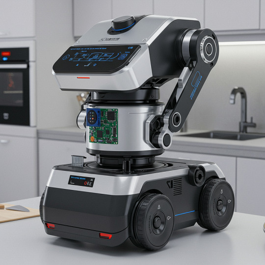
Table of Contents
Why Hygiene Matters in a Cooking Robot
How Electronics Design Improves Cooking Robot Hygiene
Sensor Integration for Real-Time Hygiene Monitoring
Sealed PCB Design for Wash-Down Protection
Built-In Cleaning Automation
Touchless Control Systems
Real-World Scenario: Electronics Design Enabling Hygiene
Meeting Global Food Safety Standards
What’s Next: Future of Hygiene in Cooking Robots
Key Takeaways
Conclusion
Smart electronics design plays a critical role in maintaining hygiene in a cooking robot. From precision control to built-in sanitation systems, advanced electronics ensure that cooking robots meet the highest cleanliness and food safety standards. Whether it’s managing temperature, automating cleaning, or preventing contamination, the secret to hygienic food automation lies in how the electronics are designed.
If you’re exploring how modern cooking robots stay clean, safe, and food-ready, the answer begins with smart, reliable electronics design. Let’s break down how this works — and why it matters.
Why Hygiene Matters in a Cooking Robot
In commercial kitchens, food factories, or even smart homes, a cooking robot handles critical tasks like chopping, frying, stirring, or mixing. Because they come into direct contact with food, hygiene isn’t just about cleanliness — it’s vital for health, compliance, and preventing cross-contamination.
Contamination risks may include:
Leftover food residues
Cross-contact between raw and cooked items
Improper temperature management
Bacteria buildup in hard-to-clean areas

How Electronics Design Improves Cooking Robot Hygiene
1. Sensor Integration for Real-Time Hygiene Monitoring
Smart sensors integrated into the cooking robot help monitor:
Surface cleanliness
Sanitization temperatures
Moisture levels that signal bacterial growth
These sensors help the robot take action — whether it’s sounding alerts or starting cleaning cycles — making electronics design a key part of hygiene management.
2. Sealed PCB Design for Wash-Down Protection
In hygiene-sensitive environments, the electronics design includes:
Waterproof PCB coatings
Isolated high-voltage components
IP67+ enclosures for safe wash-downs
This allows the cooking robot to be cleaned externally without damaging the electronics, maintaining both hygiene and reliability.
3. Built-In Cleaning Automation
Electronics power intelligent hygiene functions like:
Pre-programmed cleaning schedules
Motor control for rotating brushes and sprayers
Hot water and detergent dispensers
These automated systems reduce manual intervention and improve hygiene consistency across every cooking cycle.
4. Touchless Control Systems
Modern cooking robots feature touchless controls to avoid surface contamination. These include:
Gesture or voice recognition
Infrared sensors for non-contact operation
Capacitive proximity-based interfaces
Such innovations are only possible through thoughtful electronics design that enhances hygiene while improving user experience.
Real-World Scenario: Electronics Design Enabling Hygiene
Imagine a robotic kitchen unit preparing soups:
Sensors detect residue inside the container
A cleaning cycle is triggered automatically
Electronics control nozzles, heat, and drainage
Sealed circuits protect the system during cleaning
Here, hygiene, automation, and electronics design work together to ensure safe and sanitary operation.
Meeting Global Food Safety Standards
HACCP guidelines
FDA and EU food-grade equipment regulations
NSF/ANSI safety standards
A strong electronics design not only automates hygiene but helps manufacturers log cleaning activity and prove compliance with regulations.
What’s Next: Future of Hygiene in Cooking Robots
Emerging electronics design trends are pushing hygiene even further:
AI-Powered Hygiene Monitoring: Adaptive cleaning schedules and anomaly detection
IoT for Hygiene Reports: Remote access to logs, diagnostics, and alerts
Self-Cleaning Tech: UV light modules and antimicrobial surfaces managed by electronics
These innovations promise a future where cooking robot hygiene becomes smarter, faster, and more autonomous.
Key Takeaways
Hygiene is a critical factor in every cooking robot application
Smart electronics design enables better hygiene through sensors, automation, and protective enclosures
Sealed systems, real-time detection, and automated cleaning are only possible through modern electronics
Investing in better design reduces contamination risk and ensures compliance with food safety standards
Conclusion
A cooking robot is only as clean as its electronics allow it to be. By integrating cutting-edge sensors, sealed PCBs, and automated cleaning capabilities, electronics design plays a central role in ensuring hygiene in robotic kitchens. As the demand for automation in food preparation rises, smarter electronics will remain the backbone of safe, hygienic cooking technologies.
Hygiene isn’t optional — it’s a core feature that defines the success of any cooking robot. And it starts with smarter electronics design.
Whether you’re building the next generation of kitchen robotics or optimizing hygiene in automated food systems, the right design partner helps you move from idea to market with precision and safety built-in.
Discover how advanced electronics design can elevate hygiene in cooking robots. 🔗 Learn more at www.auckam.com
0 notes