#code arduino digital lock
Explore tagged Tumblr posts
Visit Tumblr Blog
Explore Tumblr blogs with no restrictions, modern design and the best experience.
Last Seen Tumblr Blogs


Fun Fact
Tumblr’s website traffic is steadily declining.
Text
Price: [price_with_discount] (as of [price_update_date] - Details) [ad_1] The Arduino is a cheap, flexible, open source microcontroller platform designed to make it easy for hobbyists to use electronics in homemade projects. With an almost unlimited range of input and output add-ons, sensors, indicators, displays, motors, and more, the Arduino offers you countless ways to create devices that interact with the world around you.In Arduino Workshop, you'll learn how these add-ons work and how to integrate them into your own projects. You'll start off with an overview of the Arduino system but quickly move on to coverage of various electronic components and concepts. Hands-on projects throughout the book reinforce what you've learned and show you how to apply that knowledge. As your understanding grows, the projects increase in complexity and sophistication.Among the book's 65 projects are useful devices like:– A digital thermometer that charts temperature changes on an LCD–A GPS logger that records data from your travels, which can be displayed on Google Maps– A handy tester that lets you check the voltage of any single-cell battery– A keypad-controlled lock that requires a secret code to openYou'll also learn to build Arduino toys and games like:– An electronic version of the classic six-sided die– A binary quiz game that challenges your number conversion skills– A motorized remote control tank with collision detection to keep it from crashingArduino Workshop will teach you the tricks and design principles of a master craftsman. Whatever your skill level, you'll have fun as you learn to harness the power of the Arduino for your own DIY projects.Uses the Arduino Uno board Publisher : No Starch Press; 1st edition (13 May 2013) Language : English Paperback : 392 pages ISBN-10 : 1593274483 ISBN-13 : 978-1593274481 Item Weight : 726 g Dimensions : 17.98 x 2.31 x 23.5 cm Country of Origin : USA [ad_2]
0 notes
Text
Introduction to Internet of Things (IoT) Programming

The Internet of Things (IoT) is revolutionizing the way we interact with devices, allowing everyday objects to connect to the internet and share data. From smart homes and wearables to industrial automation, IoT is reshaping the world. In this post, we'll dive into the basics of IoT programming and how you can start creating your own smart applications.
What is IoT?
IoT refers to a network of physical devices embedded with sensors, software, and other technologies to connect and exchange data with other devices and systems over the internet.
Key Components of IoT Systems
Devices/Sensors: Physical components that collect data (e.g., temperature sensors, motion detectors).
Connectivity: Wi-Fi, Bluetooth, Zigbee, LoRa, or cellular networks to transmit data.
Data Processing: Microcontrollers or cloud services process the incoming data.
User Interface: Web/mobile applications to monitor and control devices.
Popular IoT Hardware Platforms
Arduino: An open-source electronics platform based on simple microcontrollers.
Raspberry Pi: A small, affordable computer ideal for more powerful IoT applications.
ESP8266/ESP32: Low-cost Wi-Fi-enabled microchips widely used in IoT projects.
Languages Used in IoT Programming
C/C++: Commonly used for low-level programming on microcontrollers like Arduino.
Python: Popular for Raspberry Pi and edge computing due to its simplicity.
JavaScript (Node.js): Useful for IoT dashboards and server-side applications.
MicroPython: A lightweight version of Python optimized for microcontrollers.
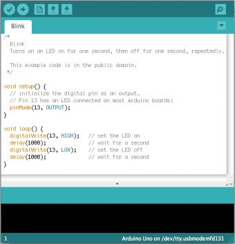
Example: Blinking an LED with Arduino
void setup() { pinMode(13, OUTPUT); // Set digital pin 13 as output } void loop() { digitalWrite(13, HIGH); // Turn the LED on delay(1000); // Wait for 1 second digitalWrite(13, LOW); // Turn the LED off delay(1000); // Wait for 1 second }
IoT Data Handling and Cloud Integration
Once your devices are collecting data, you'll need to store and analyze it. Here are some common platforms:
ThingSpeak: A simple platform for IoT data logging and visualization.
Firebase: Real-time database ideal for mobile IoT applications.
AWS IoT Core: Scalable cloud service for managing IoT devices.
MQTT Protocol: Lightweight messaging protocol used for IoT device communication.
Popular IoT Projects to Try
Smart door lock controlled by a mobile app
Home temperature monitor with alerts
Motion detection security camera
Plant watering system based on soil moisture levels
Fitness tracker using accelerometers
Best Practices for IoT Programming
Use lightweight protocols and efficient code to conserve resources.
Secure your devices with strong authentication and encryption.
Plan for over-the-air (OTA) updates to patch software bugs.
Reduce power consumption for battery-powered devices.
Test in real-world conditions to ensure reliability.
Conclusion
IoT programming opens the door to endless possibilities for innovation and automation. Whether you're just blinking LEDs or building a smart home system, learning IoT programming will give you the skills to bring physical objects to life through code. Start simple, keep exploring, and gradually build smarter and more connected projects.
0 notes
Video
youtube
Examination Room Guide using FINGER PRINT, RFID with Arduino and GSM-SMS Alert Jumbling System EXAMS | Examination Guide using RFID and Fingerprint Module for Jumbling System with Arduino | examination room guidance system using rfid and Arduino | examination room guide using rfid | fingerprint based bank locker system using arduino | fingerprint based electronic voting machine using arduino ppt | automated attendance system with finger print and gsm | attendance management with biometric and sms alerts | automatic ration distribution system using gsm and rfid.***********************************************************If You Want To Purchase the Full Working Project KITMail Us: [email protected] Name Along With You-Tube Video LinkWe are Located at Telangana, Hyderabad, Boduppal. Project Changes also Made according to Student Requirementshttp://svsembedded.com/ https://www.svskits.in/ http://svsembedded.in/ http://www.svskit.com/M1: 91 9491535690 M2: 91 7842358459 We Will Send Working Model Project KIT through DTDC / DHL / Blue Dart / First Flight Courier ServiceWe Will Provide Project Soft Data through Google Drive1. Project Abstract / Synopsis 2. Project Related Datasheets of Each Component3. Project Sample Report / Documentation4. Project Kit Circuit / Schematic Diagram 5. Project Kit Working Software Code6. Project Related Software Compilers7. Project Related Sample PPT’s8. Project Kit Photos9. Project Kit Working Video linksLatest Projects with Year Wise YouTube video Links157 Projects https://svsembedded.com/ieee_2022.php135 Projects https://svsembedded.com/ieee_2021.php 151 Projects https://svsembedded.com/ieee_2020.php103 Projects https://svsembedded.com/ieee_2019.php61 Projects https://svsembedded.com/ieee_2018.php171 Projects https://svsembedded.com/ieee_2017.php170 Projects https://svsembedded.com/ieee_2016.php67 Projects https://svsembedded.com/ieee_2015.php55 Projects https://svsembedded.com/ieee_2014.php43 Projects https://svsembedded.com/ieee_2013.php1100 Projects https://www.svskit.com/2022/02/900-pr...***********************************************************1. RFID Based Access Control System Using Arduino | Arduino to Excel Communication (PLX-DAQ) | Library,2. DIY Smart Auto Billing Shopping Trolley Using Arduino Automated Shopping Cart with Add/Delete ITEMS,3. Smart Door Locks Security System using ESP32-CAM with QR Code,4. Digital Temperature Controller | Temperature Controlled Fan Using 8051,5. GSM Based Smart Energy Meter with Arduino Project,6. Arduino Based Automatic Engine Locking System for Drunken Drivers,7. Medicine Reminder System | Smart Medicine Pill Reminder Project,8. Smart E - Agriculture Monitoring Based on Arduino With Android App
0 notes
Text
Tutorial ESP32 Kunci Pintu 3in1 Fingerprint Keypad 4x3 dan RFID PN532
Tutorial ESP32 Kunci Pintu 3in1 Fingerprint Keypad 4×3 dan RFID PN532
Kunci pintu digital atau digital door lock merupakan projek yang banyak diminati oleh banyak orang, dan kali ini saya akan membuat kunci pintu digital yang di akses dengan tiga jenis sensor ESP32, Keypad 4×3, Fingerprint dan RFID PN532. Solenoid door lock yang saya gunakan adalah modul digital lock yang ada dipasaran seharga 40 ribu rupiah an, sedangkan untuk driver nya saya menggunakan modul…

View On WordPress
#arduino digital door lock#code arduino digital lock#digital door lock keypad#digital lock esp32#projek digital door lock fingerprint#projek digital door lock rfid#proyek kunci pintu digital
0 notes
Text
Arduino 1.8.5 themes

It generates the clock, acts like a serial port, acts like a disk drive, and so on. The little computer project uses a real Z80 chip and uses an ATMega32A for almost all the support functions. In another way, it is very difficult because the tools want to help you so badly. How hard can it be to update the buffer? In one way, it is trivial. It did seem to work with the default 64-byte buffer, but XModem sends more data than that and it would be easy to imagine it getting overrun. But the upshot was that for XModem transfers, felt like the default Arduino serial buffer wasn’t big enough to be reliable. Details are available in a discussion on Hackaday.io, if you really want to follow it. I won’t bore you with the details about getting the board to work since you will only care if you have one. The Issue: Arduino Serial Buffer Size Limit It’s a trick worth knowing as it will come in handy beyond this single problem. What I ended up with is a way to make your own menus in the Arduino IDE to set compiler options based on the target hardware for the project. I wanted better, and that sent me down a Saturday morning rabbit hole. It looked like the best bet was to do Intel hex files and transfer them copy and paste across the terminal. The only problem was there were not many good options for transferring data back and forth to the PC. But I finally found time to finish it and had CP/M booted up. I got the PCB and - you guessed it - it sat some more, partially assembled. The parts sat partially assembled for a while and then a PCB came out for it. I rarely have time to build things I write about, but I really wanted to try this little computer. A while back I’d written about the $4 Z80 computer by. No matter how you craft your personal environment, the minute your code hits the Internet, someone will try to use it in the IDE. But when you produce things for other people to use, you almost can’t ignore it. On the other hand, I was impressed with how extensible it was if you can dig out the details of how it works internally.įirst, you might wonder why I use the IDE. On the one hand, I despise the lackluster editor for hiding too much detail from me and providing little in the way of useful tools. The solution I arrived at might help you do some other things, so even if you don’t need that exact feature, you still might find it useful to see what I did.įollowing this experience I am genuinely torn. I realized just how much heartburn the other day when I wanted to something very simple: increase the receive buffer on an ATmega32 serial port. But the original IDE always gives me heartburn.
Granted, these days you have more options with the pro IDE and Platform IO, for example. It is pretty well-known that I’m not a big fan of the Arduino infrastructure. Locks and security are our bread and butter, so enjoy some physical key appreciation and digital lock love. We are in advanced territory now, but keep this inspiration train going and drop us a tip to share something you make with this miniature deadbolt. You will be compiling your sketch in Arduino’s IDE, but uploading through ST-Link across some wires you will have to solder. There are a couple of tables for the controller pins and header for your convenience.
The Github upload instructions are illustrated, and you know we appreciate documentation. Three, it’s a piece of (minimal) security hardware, but who knows where that can scale. Two, someone saw a tool they wanted to control and made it happen.
One, the Arduino banner covers a lot of programmable hardware, and it is a powerful tool in a hardware hacker’s belt. connected a Rothult unit to the Arduino IDE in response to Ripping up a Rothult. We are continuously inspired by our readers which is why we share what we love, and that inspiration flows both ways.
0 notes
Text
How to Repair a Car Computer
You may be wondering what your car's computer is and how to fix it. You can learn about the engine control module, the Analog-to-Digital converter, the CANbus network, and the 32-bit processor by reading this article. Once you understand these components, you can easily repair your car computer. You can also read more about the different components of the car computer by going to Solo Auto Electronics. The company has step-by-step instructions that are easy to follow.
Engine control module (ECU)
What is the function of the Engine Control Module (ECU) in your car? The ECM controls the function of the entire engine, including the air-fuel mixture, anti-lock brake system, and other systems. This computer receives information from several sensors and regulates their function, as well as allowing the engine to function properly. If you're having trouble with your vehicle's ECU, you may want to read on to learn more about it.
An ECU controls many different systems in the engine, including the ignition system and the fuel injection system. The ECU records its own information and can control the timing of a spark to ignite the fuel. It also regulates the opening angle of the electronic throttle body to maintain the proper idle speed. Some models have the ability to control the radiator cooling fan and the engine's air-conditioning system. The ECU is an extremely sophisticated part of the car computer, and it is the most important part of the car computer.
Analog-to-digital converters
An analog-to-digital converter (ADC) is a device used to convert an analog phenomenon into a digital signal that can be processed by a computer. Today, virtually all music is digitized and distributed over the internet, and almost all scientific instruments are digitized. Analog outputs of sensors are converted to digital signals for display, recording, and analysis. The technology behind ADCs can be found in most cars.
A typical analog-to-digital converter converts an analogue signal to a digital value by sampling the analog signal on a rising or falling edge of the sample clock and then converting the signal to a corresponding digital value. The output is then approximated to a fixed level of precision. The accuracy of the digitized output is determined by two factors: the sampling rate and the quantization level.
32-bit processor
Compared to the current generation of car CPUs, which are largely eight-bit devices, a 32-bit car computer processor is more sophisticated and can offer more features to the driver. Among them are complete climate control through graphics and a locking facility. Other features include audio and video systems and interactive navigation systems. The next step in the evolution of car computing is to create 32-bit car computers with higher processing speeds.
Embedded systems, like the one used in most cars, consist of multiple microcontrollers. These are used to automate car parts and increase their efficiency. Most ECUs have one or more microcontroller CPUs. Infineon, for example, makes 32-bit car microcontrollers with embedded flash memory. For these systems, a 32-bit car computer processor is the ideal solution. Its high-speed operation can support applications such as autonomous driving and connected services automation.
CANbus network
The CAN bus network is a series of bus lines that are interconnected in the vehicle computer to transmit data between devices. This data is referred to as CAN bus. Different types of CAN bus systems may use different data formats and IDs, but they all share the same data. The smallest image of a CAN bus message is referred to as the "frame" and is the layout of useful data within the message. The Arduino demo code outputs this smallest image.
CAN buses are available in different speeds. Low-speed versions are used for seat and window controls. High-speed versions are used for the engine, anti-lock brakes, and cruise control. A vehicle may have two or three CAN bus networks. Some vehicles may have one dedicated for safety. In general, the CAN bus is backwards compatible with CAN 2.0, which is the standard used in many modern cars.
0 notes
Text
A Future Where Everything Becomes a Computer Is as Creepy as You Feared
By Farhad Manjoo, NY Times, Oct. 10, 2018
More than 40 years ago, Bill Gates and Paul Allen founded Microsoft with a vision for putting a personal computer on every desk.
No one really believed them, so few tried to stop them. Then before anyone realized it, the deed was done: Just about everyone had a Windows machine, and governments were left scrambling to figure out how to put Microsoft’s monopoly back in the bottle.
This sort of thing happens again and again in the tech industry. Audacious founders set their sights on something hilariously out of reach--Mark Zuckerberg wants to connect everyone--and the very unlikeliness of their plans insulates them from scrutiny. By the time the rest of us catch up to their effects on society, it’s often too late to do much about them.
It is happening again now. In recent years, the tech industry’s largest powers set their sights on a new target for digital conquest. They promised wild conveniences and unimaginable benefits to our health and happiness. There’s just one catch, which often goes unstated: If their novelties take off without any intervention or supervision from the government, we could be inviting a nightmarish set of security and privacy vulnerabilities into the world. And guess what. No one is really doing much to stop it.
The industry’s new goal? Not a computer on every desk nor a connection between every person, but something grander: a computer inside everything, connecting everyone.
Cars, door locks, contact lenses, clothes, toasters, refrigerators, industrial robots, fish tanks, sex toys, light bulbs, toothbrushes, motorcycle helmets--these and other everyday objects are all on the menu for getting “smart.” Hundreds of small start-ups are taking part in this trend--known by the marketing catchphrase “the internet of things”--but like everything else in tech, the movement is led by giants, among them Amazon, Apple and Samsung.
For instance, Amazon last month showed off a microwave powered by Alexa, its voice assistant. Amazon will sell the microwave for $60, but it is also selling the chip that gives the device its smarts to other manufacturers, making Alexa connectivity a just-add-water proposition for a wide variety of home appliances, like fans and toasters and coffee makers. And this week, both Facebook and Google unveiled their own home “hub” devices that let you watch videos and perform other digital tricks by voice.
You might dismiss many of these innovations as pretty goofy and doomed to failure. But everything big in tech starts out looking silly, and statistics show the internet of things is growing quickly. It is wiser, then, to imagine the worst--that the digitization of just about everything is not just possible but likely, and that now is the time to be freaking out about the dangers.
“I’m not pessimistic generally, but it’s really hard not to be,” said Bruce Schneier, a security consultant who explores the threats posed by the internet of things in a new book, “Click Here to Kill Everybody.”
Mr. Schneier argues that the economic and technical incentives of the internet-of-things industry do not align with security and privacy for society generally. Putting a computer in everything turns the whole world into a computer security threat--and the hacks and bugs uncovered in just the last few weeks at Facebook and Google illustrate how difficult digital security is even for the biggest tech companies. In a roboticized world, hacks would not just affect your data but could endanger your property, your life and even national security.
Mr. Schneier says only government intervention can save us from such emerging calamities. He calls for reimagining the regulatory regime surrounding digital security in the same way the federal government altered its national security apparatus after the Sept. 11, 2001, attacks. Among other ideas, he outlines the need for a new federal agency, the National Cyber Office, which he imagines researching, advising and coordinating a response to threats posed by an everything-internet.
“I can think of no industry in the past 100 years that has improved its safety and security without being compelled to do so by government,” he wrote. But he conceded that government intervention seems unlikely at best. “In our government-can’t-do-anything-ever society, I don’t see any reining in of the corporate trends,” he said.
Those trends are now obvious. It used to be difficult to add internet connectivity to home devices, but in the last few years the cost and complexity of doing so have plummeted. Today, off-the-shelf minicomputers like the Arduino can be used to turn just about any household object “smart.” Systems like the one Amazon is offering promise to accelerate the development of internet-of-things devices even further.
At a press event last month, an Amazon engineer showed how easily a maker of household fans could create a “smart” fan using Amazon’s chip, known as the Alexa Connect Kit. The kit, which Amazon is testing with some manufacturers, would simply be plugged into the fan’s control unit during assembly. The manufacturer also has to write a few lines of code--in the example of the fan, the Amazon engineer needed just a half-page of code.
And that’s it. The fan’s digital bits (including security and cloud storage) are all handled by Amazon. If you buy it from Amazon, the fan will automatically connect with your home network and start obeying commands issued to your Alexa. Just plug it in.
This system illustrates Mr. Schneier’s larger argument, which is that the cost of adding computers to objects will get so small that it will make sense for manufacturers to connect every type of device to the internet.
Sometimes, smarts will lead to conveniences--you can yell at your microwave to reheat your lunch from across the room. Sometimes it will lead to revenue opportunities--Amazon’s microwave will reorder popcorn for you when you’re running low. Sometimes smarts are used for surveillance and marketing, like the crop of smart TVs that track what you watch for serving up ads.
Even if the benefits are tiny, they create a certain market logic; at some point not long from now, devices that don’t connect to the internet will be rarer than ones that do.
The trouble, though, is that business models for these device don’t often allow for the kind of continuing security maintenance that we are used to with more traditional computing devices. Apple has an incentive to keep writing security updates to keep your iPhone secure; it does so because iPhones sell for a lot of money, and Apple’s brand depends on keeping you safe from digital terrors.
But manufacturers of low-margin home appliances have little such expertise, and less incentive. That’s why the internet of things has so far been synonymous with terrible security--why the F.B.I. had to warn parents last year about the dangers of “smart toys,” and why Dan Coats, the director of national intelligence, has identified smart devices as a growing threat to national security.
Connecting everything could bring vast benefits to society. But the menace could be just as vast. Why not go slowly into the uncertain future?
1 note
·
View note
Text
Create your own crack the code game with an Arduino-controlled safe

Michael Klements’ Arduino Uno-controlled “safe” may not be the most secure model that you can find, but it certainly looks like a very entertaining puzzle.
Users can place whatever “treasure” they want hidden inside, shut the door, and press a rotary encoder button to lock it via a micro servo. They then must decipher a randomly generated four-digit code to get it open again.

Number guesses are input using the encoder dial on the front, which are displayed by a small OLED I2C screen. Green and red LEDs provide feedback as to how many digits are correct and if they’re in the right position, eventually letting users figure out where everything goes by a process of elimination.
youtube
Create your own crack the code game with an Arduino-controlled safe was originally published on PlanetArduino
0 notes
Text
[Something awesome] iteration #6 [FINAL]
This is my last blog about my awesome project. There were so many problems happened along the way before I finished this blog. My Raspberry Pi got bricked 3 hours after I had finished integrating hardware and software components together. So I had no chance to record the video of it.
I spent fully 2 and days to reinstall the and set things up in my spare raspberry pi (As I mentioned in #5.5). However, it did not turn out as I had expected. Raspbian Buster, the latest version of the raspberry pi operating system, created for Raspberry Pi 4 which is the new model, is not 100% compatible with my model B+ and causes so many trouble while installing OpenCV module which takes 2-3 hours each time. It kept ending with error installation around 88-100% of the installation. I tried 5 different versions of this module (3.4, 3.4.1, 3.2.0, 4.0.0, 4.0.1) but all of them failed. I felt kind of regret that I did not take a video of my project before it got brick.
Fortunately, Last night at 3am, I decided to move on and looking for a way to make my software run in Arduino UNO in order to have some simulation to be shown in the presentation. Thanks to my Thai electrical engineering friend that guided me through this. So apart from how to do GPIO programming in python (for Raspberry Pi), I would write about how to control Arduino UNO through pyFirmata (module for python3) as another extension that was not mentioned in the proposal.
Redesigned Circuit

This is my new circuit connection. One more LED diode has been added and move the 5V DC source to NC side of the relay module. This would make the circuit to have 2 led color that can indicate door being locked or unlocked.
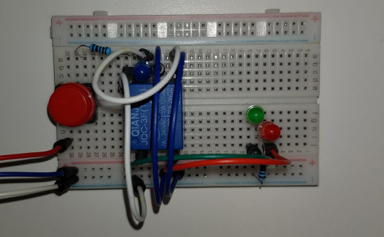
This is what it looks like in the real connection. It becomes way cleaner than the previous one having very messy wires and jumpers.

The green light indicates that the door is unlocked, while red is the opposite way.
GPIO programming for Raspberry Pi
Example of GPIO programming on Raspberry Pi
After I have both software and hardware prepared good enough to be put together, the time that I have been waiting for so long is here!
Let’s put them together and create a really cool facial recognition doorknob system. What I have to do is just set the digitalWrite signal to enable the relay module once my face is detected.
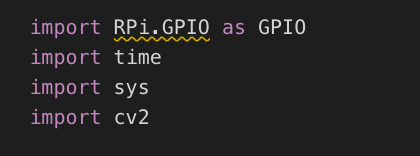
Firstly, the GPIO module is needed if this software is going to run on Raspberry Pi. It basically allows you to access all the pin on the board.
Next step is about to pick one pin as an output. The code below takes care of that.
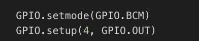
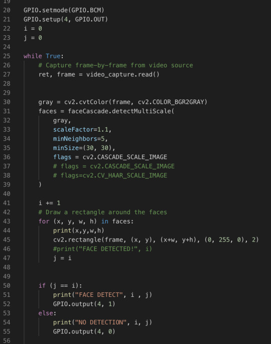
Then add a couple line of codes to make the pin to send digital output to the GPIO port in our circuit. A new code including line 22, 23, 41, and 50 to 55. It is very basic logic.
pyFirmata programming for Arduino UNO
This section is an additional one from having bricked Raspberry Pi. It is just to test that software and hardware can run together correctly because all of the computational parts are done by the laptop connected to Arduino. So the board is basically just a tool to send a digital signal to the circuit, no computation stuff at all.

So a module taking care of controlling the output pin in this time is pyFirmata. To do this you need to upload a standard program of Firmata into the Arduino board.

Arduino software provides you this program. You do not even have to learn how to code about this. PyFirmata is a program that changes your Arduino, that usually perform a software part, this burden is pushed to the high-level programming side (python in this time). So we can do everything, for example, reading and writing the pins.

The codes above have to be added into the main program of the recognition. It just specifies the port address connecting to the board, sets input and output pins.
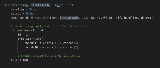
The first method is the detect. It is almost exactly the same as in iteration #5. The only difference is that I changed i and j into the boolean flags.
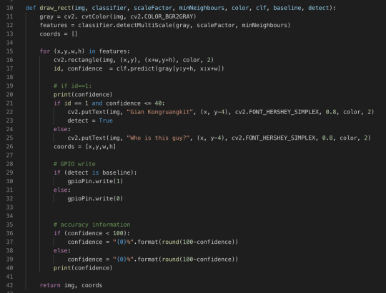
This is pretty much the same as last iteration’s code as well. Lines 28 to 32 are added. Just only 4 lines of code, we can have our system run on Arduino UNO! Isn’t it cool?
Running the program!
After all the time I spent on this project, this is the moment I have been waiting for. The facial recognition system that I created myself, got out of my comfort zone to build it from the scratch and researched heaps of self-learning. This video below could describe everything.
Video of the final result
Conclusion
This is a very long journey for me. I have learned a lot and my perspective of computer vision technology has been completely changed as well. I was really excited and proud of myself in the presentation today when I tested my program and shown it in the class. The reaction of everyone in the tutorial class made me feel like all the hard work paid off. Although my ways of explaining things are not that good, I hope you enjoy my blog and can gain at least some new knowledge from it. Cheers!
0 notes
Text
2 weeks in - Bringing our ideas together
We are 2 weeks in and our project’s general theme and direction has been decided and agreed by the team. We have settled on using an attic on campus and the team inspected the site today. Our plans are definitely coming together, with each member of the team bringing different skills. Johnny - our music expert is currently playing with the sound to fit our theme. He will be working on down-sampling and bit crushing with loops and granular synthesis. A good idea raised by Johnny was to enhance the experience by using the player’s voice and distort it which could really hit the fan when it comes to gradually raising the bar of creepiness. Rees’ work on emulating Facebook’s and Twitch’s web pages are coming along very nicely, imitating every element of those websites to perfection. Tod - bringing creative computing to our project, currently working on a concept idea around using pointillism which slowly draws the player’s picture to gradually reveal them at the end as well as designing some of the room’s aesthetics with articles and breaking news images, with the use of Photoshop to create a creepy crime related theme. Bobby - our physical computing guy has been putting together well thought ideas in regards to the hardware we could use for the puzzles involved in this project, from the mechanic of using an old rotary phone to a locked chest box being unlocked with a player accessing a shredder which could hold the dramatic ending to our piece.
Some general rules/ideas we’re bringing together :
No longer than 20 minute per player’s session.
Single player experience
Countdown timer displayed for the player.
Sound includes a degraded theme and old digital transferred data sound.
The lighting could indicate the mood and the time remaining, hopefully to be able to control real-time.
Emulated Facebook to update the profile of the player and their status.
The use of pointillism to reveal the players face at the end.* - Tod
A mannequin head attached to a servo that follows a player around using infrared sensors and an Arduino. * - Bobby
CCTV camera where a player session could be recorded and shown to the player as well, but to overwrite it with old recordings (maybe for clues)
For aesthetic effects, there can be many screens in the room (imitating stalking) and a pin board where we can place clues for the players
An old recording camera and the rotating dial phone should also give a chilling sensation.
The puzzles are yet finalised and we are reminded by Sarah that the element of creepiness should gradually elevate as each puzzle is solved throughout the 20 minutes. There should also be a reason behind everything which we will keep in mind when designing puzzles.
Puzzle to possibly include a padlock (or any lock device) to have the code as the player’s DOB.
Ending right now is the shredder which we plan to have the player shred information which are so easily obtained by us of them, conveying a message about data privacy.
* These contain elements of past projects by our team members and will be considered for use for additional aesthetic purposes for the experience rather than core puzzles.
- Tod
0 notes
Text
Virtual Arduino Project

In order for my project to meet all the requirements I added a moving part, the servo which represents a lock. Once a person is close to the sensor the alarm will sound and one will be given the opportunity to enter the 3-digit code and unlock the door.
0 notes
Text
UOttaHack3 Challenge: Leveraging Solace PubSub+ to Power a Smart Delivery System
uOttaHack is Ottawa’s largest hackathon that takes place every year at Ottawa University. This year’s event welcomed over 400 students from a variety of backgrounds to collaborate, participate, and innovate! As a prime sponsor of the uOttaHack3 event, Solace challenged students to leverage the PubSub+ Event Broker: Cloud technology to create something truly unique.
A group of three students from Concordia University worked together to build a smart delivery system to deter people from stealing packages and enable real-time delivery notifications.
Jay Wreh – one of the three students on the project – describes their project in detail below:
The Solace Challenge Winner – SmartBox Delivery System
At uOttaHack 3, a student hackathon hosted at uOttawa, we built the SmartBox Delivery System. Our project won the Solace Challenge for the best use of Solace PubSub+ Event Broker: Cloud.
SmartBox Delivery is an end-to-end system that allows independent couriers to easily and securely deliver their parcels and packages, making porch pirates and missed delivery notices a thing of the past!
How It Works
Scanning a package in the app.
At the sorting facility, a delivery agent scans a customer’s package through the SmartBox Delivery app. This will automatically reserve an available SmartBox that is the nearest to the customer. When it comes time for the delivery, the package is placed inside the allocated box, after which it will automatically close and lock once the delivery person marks the items as delivered.
When the customer is ready for pickup, they simply scan the SmartBox containing their package and the box will automatically unlock and open for them to retrieve their order. Customers can also choose to subscribe to notifications through various channels, including smart assistants like Alexa!
Under the Hood
The system is comprised of three main components: the mobile application, the backend service, and the external clients (which includes the SmartBoxes themselves).
By leveraging Solace PubSub+ Platform as a messaging service, the backend and external clients are able to instantly communicate through an event-driven architecture. More specifically, Solace PubSub+ Platform was used to publish events for the SmartBoxes to listen and react to. For instance, a ‘PO_BOX_RESERVE_REQUEST_EVENT’ is published by the backend service once a delivery agent is ready to start a delivery of one or more packages:
/* * Starting a delivery agent's trip */ const addTrip = async (request, h) => { try { let succesful = []; let failed = []; let poBoxes = []; for (const orderId of orderIds) { try { const order = await getCustomerOrder(orderId); const box = await reservePOBox(order); // Publish event for target box to messagingClient.publish(PO_BOX_RESERVE_REQUEST_EVENT, JSON.stringify({ boxId: box.id })); // Record reserved SmartBoxes poBoxes = [...poBoxes, box]; // Record orders that were successfully assigned a SmartBox succesful = [...succesful, order]; } catch (error) { // Record any orders that the system was unable to assign a SmartBox failed = [...failed, order]; } } const id = await addTrip({ userId, succesful }); return h.response({ id, failed, poBoxes }).code(200); } catch (error) { return h.response({ message: error.message }).code(500); } }
The SmartBox, which is subscribed to that event, will then glow red and mark itself as reserved once the event is received.
Here is an example of a code snippet for the SmartBox controller listening for the event:
RESERVE = "PO_BOX_RESERVE_REQUEST_EVENT" ... # Subscribe to events def on_connect(client, userdata, flags, rc): ... client.subscribe(RESERVE) ... ... # When an event is received via Solace def on_message(client, userdata, msg): payload = json.loads(msg.payload.decode()) if (payload['boxId'] == PO_BOX_ID): if msg.topic == RESERVE: # The value '1' indicates the reserved state arduino_message = 1 ... ... # Send the command to the microcontroller arduinoOut.write(str(arduino_message).encode()) ...
Once the delivery agent deposits the package into its respective SmartBox and confirms its delivery, a `PACKAGE_DELIVERED_EVENT`event is published:
const deliverOrder = async (request, h) => { try { const { boxId } = request.params; const box = await getPOBox(boxId); // Update order status to delivered let { order } = box; order.status = 'DELIVERED'; await updateOrder(order); // Publish delivery event for corresponding box to close messagingClient.publish(PACKAGE_DELIVERED_EVENT, JSON.stringify({ boxId })); return h.response({ message: `Order with id=<${order.id}> was successfully delivered` }).code(200); } catch(error) { return h.response({ message: error.message }).code(500); } }
On reception of the event, the SmartBox reserved for the specific customer order closes and locks. A similar sequence of events occurs at the final step, when the customer goes to retrieve their package.
Inside the SmartBox
The delivery system was based on a wonderful proof of concept of the SmartBox hardware, built out of a used, resilient, and durable cardboard box. The “Smart” in the SmartBox is an Arduino Uno, connected to a computer using a serial communication channel. This allows commands to be sent to the box upon reception of events.
Two micro servos, along with an extension connected to a pivot system on the latches served to open and close the box on demand. Another micro servo was used to raise a flag attached to the box; this one being activated when an object broke an IR beam installed inside. These sensors were sensitive and accurate and allowed for instantaneous feedback when the package was placed in the SmartBox.
Finally, we had a digital RBG LED strip attached to the front to display the state of the system tothe user. An example of this would be to glow green when the box is available for reservation.
What we learned
We learned so much during our time at uOttaHack 3 including how easy it is to configure a message broker within Solace PubSub+ Platform. Integrating our backend with the cloud message broker was really simple thanks to Solace’s Node.js and Python starter examples. Through discussions with Solace representatives, we were also able to solidify our understanding of event-driven architecture and why it is so useful. In our case, we found that communication between various IoT devices was a perfect use case for Solace PubSub+ Platform.
Final Thoughts
Solace’s PubSub+ Event Broker is an amazing way to integrate real-time scalable messaging to any project. For us, it helped to abstract and simplify the communication of our backend service to IoT devices such as the SmartBox we built and Amazon Alexa.
Thank you to the Solace team at uOttaHack 3 for taking interest in our project and helping us bring our ideas from our heads into the real world!
You can explore more of the SmartBox Delivery System code on GitHub.
The post UOttaHack3 Challenge: Leveraging Solace PubSub+ to Power a Smart Delivery System appeared first on Solace.
UOttaHack3 Challenge: Leveraging Solace PubSub+ to Power a Smart Delivery System published first on https://jiohow.tumblr.com/
0 notes
Text
Inquiries & Troubleshooting/6th Lab/Midterm
Inquiries/Troubleshooting
I L.O.V.E music and as a visual artist I knew that I wanted to incorporate color and music into this project; because I already double checked that I had the correct resistors and LED light with my Prof. I had all faith & hopes that I would successfully be able to execute my idea. I figured since I’m a master procrastinator, it’s not best to approach my project piece by piece; forgetting what discoveries were made from the day prior and losing the flow of creativity and vigor. My bright idea was to lock myself away for three whole days, immersing myself into the P5_computing_coding world and come out with a groundbreaking project piece…BIG MISTAKE!!!
LED-TO-BREADBOARD
· For my 1st attempt at the project, I couldn’t connect the led to the resistor; I recalled previously, times where even the professor wasn’t sure how the set-up wasn’t able to function, my remedy was to test the led light individually. I’ve found that a quick way to see if the issue may be the led light; connecting the positive side to the ground area. Swiveling the led would make the light turn on if its fully functioning.
o I noticed that the TX & RX section of the ground area for digital inputting stopped lighting up altogether; is it possible that the led light somehow damaged the socket considering only jumper cables are usually inserted?
o The led turns only when swiveled at a certain angle and held, I’m wondering if the socket may be damaged, hence ground is damaged?
P5 SKETCH-ILLUSIONS
· FRUSTRATION is the only word that continues to pop into my mind. I could not save my new file if my life depended on it. I googled solutions, skimmed P5s pages of user reference, I was able to save the other files previously but unable to tinker back-and-fro with various experiments because I was unable to save given files. Why am I unable to save my files?
· I logged in and out of P5 as a method of a quick-fix or reboot to no avail. None of the previous files from my P5 account that was previously shared and saved were able to be refurbished, what happened to these files?
LED-GUI
· Although the code for Arduino was accurate, it was unable to process the values to light up the led, I downloaded processor after I believed perhaps it was the order of operation, yet nothing happened?
· Although I ran the GUI (Arduino + processing), there was no action; I installed several variables to visually suggest uniformity yet there was always a syntax even when the code was immediately sampled as an exemplar to see if the code worked. I forward-double slashed everything yet was unable, even without that layer indirectly, to load the code to an actionable format.
· The error syntax states that there is an “unexpected declaration before ‘}’ token” I tinkered with various valuables to insert and remove yet there was always a form of a letter…back to the drawing board and more digging to do.
P5 SKETCH-SYNESTHESIA
· Recamán's Sequence was the perfect way to execute my idea, but the lining of numerals was challenging. I often used the forward slashes to see the layers of activity in sequence but there were times where I wasn’t sure the order of which to view or remove? Does sequence matter when viewing previous activity or the removal process?
· I wasn’t sure if using other shapes were messing with the integrity of the sequence, but I tried several shapes and numerical points for none-curvilinear or organic-like shapes and was unable to fully execute a free-flowing sketch. Kandinsky included overlapping lines and more edged shapes, how may I map this within the piece rather than layer a drawing an element over the canvas broadly?
· I tried to do opposite mathematical functions and inversed placement and computations of set numerals but mostly there were syntaxes errors, are the Recamán's Sequence only for even and more perfect mathematics?
· I included no fill in order to see the sketched rhythm being drawn along with the song yet I figured to include colorful strokes but the page fills way too quickly (even when the diameter was dived into the radius for example); I decided on the example and went with the arc, sliced at the diameter by pi to completely see the drawn sketch. Missing one bracket may leave the components open. I must admit, this reminds me of my failing days in math class where missing one decimal or forgetting the placement or placement value may completely render a unit of problem wrong. There were many times where I had to backtrack if the diameter evened out with the count of numbers (I had to move the count up to two or ++ in order to keep the rhythm.
· I was confident enough to attempt the midterm on my own (I wanted to challenge myself to learn the tasks before reaching out) as previously stated but didn't note such a "DUHH" factor of missing the last class because I was out sick. I didn't realize that I was missing a major component in simulating an interface that was interactive...the serial output. I assumed that the led lights and the breadboard would substitute well enough, I have a component of elements that I wanted interactive with sounds and visuals building off my previous creation of one of my favorite Artists Vassily Kandinsky but I wasn’t able to build on all shapes or use a mic to interact with the given sounds.
· Although I love that copies are made and git and github is made to save steps of activity, its really difficult to save and reopen files, I searched and google and for some reason, it seams that ill have to retype the script or completely render a new one; why is that sometimes we are and are not able to open or save a file on P5 unless copied?
· I wanted to load my own music; I tried to load the sound-file with my script and a path through .mp3 but the only options to do so I saw was in Java, is P.5 able to load personal musical sounds instead of the Java route?
· I never thought I would be doing such intense number crunches and problem word solving with theoretical problems; its really cool to see how my 7th grade…
Question: “why do I need to know about X & Y axis; when on earth am, I ever going to use this?
Answer: “Creative Computing Masters Course!!!”
P5 SKETCH-SYNESTHESIA II
· Because wavelength is on JavaScript, is that the reason I’m not able to visually load the signal from series?
· I decided to load the mouse variable “X” to draw the soundwaves since I was unable to layer and overlap different scripts
· I was unable to get the mouse moving on the top layer, which was the same issue that I had with my first sketches, I had to blind certain layer to see the process in action. I incorporated mouse X to draw along with the
***I wanted to load a Kandinsky picture as the canvas peripherals but the sketch file wouldn’t allow me to convert the file into a jpg***
P5 (Experiment)
https://www.youtube.com/watch?v=aKYlikFAV4k (SOUND MAZE)
https://www.youtube.com/watch?v=Mm2eYfj0SgA (SOUND FLOW)
https://www.youtube.com/watch?v=OAcXnzRNiCY (DANCING AS WELL)
https://www.youtube.com/watch?v=l__fEY1xanY (“)
https://www.youtube.com/watch?v=Cl_Gjj80gPE
https://www.youtube.com/watch?v=ZI1dmHv3MeM (“)
https://www.youtube.com/watch?v=4hA7G3gup-4 (DANCING WORDS)
https://www.youtube.com/watch?v=bqF9w9TTfeo vectors)
https://www.youtube.com/watch?v=pYnaBVBN QgnARQ (making sound)
https://www.youtube.com/watch?v=3noMeuufLZY (images that can run across screen in a loop)
https://www.youtube.com/watch?v=TaN5At5RWH8&list=PLRqwX-V7Uu6Zy51Q-x9tMWIv9cueOFTFA&t=0s (using mouse to make/movable objects)
https://www.youtube.com/watch?v=nfmV2kuQKwA&list=PLRqwX-V7Uu6Zy51Q-x9tMWIv9cueOFTFA&t=306s (random dots populating)
https://www.youtube.com/watch?v=nicMAoW6u1g&list=PLRqwX-V7Uu6Zy51Q-x9tMWIv9cueOFTFA&t=22s (Colour changes with dot mouse)
https://www.youtube.com/watch?v=RnS0YNuLfQQ&list=PLRqwX-V7Uu6Zy51Q-x9tMWIv9cueOFTFA&t=0s (Painting on canvas)
Java
https://www.youtube.com/watch?v=c6K-wJQ77yQ (loop of Perlin noise)
https://www.youtube.com/watch?v=fAsaSkmbF5s (NA)
https://www.youtube.com/watch?v=ccYLb7cLB1I (NA)
https://www.youtube.com/watch?v=hbgDqyy8bIw (N/A)
Other Resources
https://www.youtube.com/watch?v=4sTZQ0fa09c
https://tutorial.cytron.io/2019/07/26/simple-gui-to-control-led-on-arduino-with-processing/
Kandinsky art (Inspiration)
https://www.youtube.com/watch?v=rO6M5hj0V-o&list=PLRqwX-V7Uu6Zy51Q-x9tMWIv9cueOFTFA&t=219s
0 notes
Text
“You’ve Got Mail!” for the 19th Century
As mailboxes proliferated, inventors rushed to devise electrically enhanced versions
Photo: National Postal Museum/Smithsonian Institution
Photo: National Postal Museum/Smithsonian Institution
During the 1870s and ’80s, inventors filed more than a dozen patent applications in the United States for electrical improvements to letter boxes. But why did mailboxes and letter slots, surely among the simplest mechanical devices, have to be electrified? It was primarily a matter of convenience, for people who wanted to know exactly when the mail had arrived and didn’t want to waste time checking.
Free home delivery of the mail had begun in the United States in 1863, but mailboxes were not yet standard. Instead, a postman would knock on the door (perhaps with a handheld wooden knocker), wait for someone to answer, and then hand over the mail. If no one was home, the carrier returned later or the next day. Although this created great trust in the system, it wasn’t very efficient. In 1909, postal officials calculated that on a typical day, carriers made 360 stops and spent an average of 15 seconds per delivery, or an hour and a half a day, simply waiting.
Photos: National Postal Museum/Smithsonian Institution
A Smarter Mailbox: Ephraim E. Weaver’s electric mailbox [front and interior shown here] came with a key that the delivery person could use to ring a bell, signaling that a package had arrived.
Beginning in the 1880s, the U.S. Post Office Department began encouraging people to install a mailbox or letter slot, although they didn’t become a requirement until 1923. (For a nice concise history of the U.S. Postal Service, see The United States Postal Service: An American History 1775–2006 [PDF].)
And so, many of the early patents for electrical indicators for letter boxes tried to replace or augment the postman’s knock. Inventor Henry R. David thought that large office and apartment buildings in cities had a particular problem. His 1875 U.S. patent [PDF] detailed a system of circuits that would inform people in far-flung corners of the building that mail was waiting for them at the main entrance.
Many of the electric letter boxes, including the device that William H. Rodgers described in an 1879 patent [PDF], worked by closing a battery-powered circuit when the postman deposited letters in the box. The circuit would ring a bell inside the house. Sometimes, though, the weight of a single letter wasn’t enough to engage the circuit, as Rodgers noted in another patent that same year [PDF]. The inventor’s improved design engaged the circuit when the postman opened the box. The circuit, after ringing the distant bell, stayed locked in the on position, until the box was reopened. Obviously, Rodgers never imagined that pranksters might repeatedly open and close the box to set off the mail bell.
Charles H. Carter did spot this problem, claiming in his 1880 patent [PDF] that owners of such mailboxes were inconvenienced by “any person raising the lid or inserting any unimportant circular.” In his design, the postman would sound an alarm by means of a skeleton key. Unfortunately for Carter, the Post Office Department issued standards that required mailboxes to, among other things, allow carriers to withdraw and deposit mail “without delay.” A design that required a separate key to indicate delivery was unlikely to be approved.
Carter applied for another mailbox patent that introduced a visual indicator [PDF]. Once a letter closed the circuit, a configuration of electromagnets would expose a flap labeled “mail.” Carter suggested that the flap could also have numbers or other visual cues to call attention to the change in status.
Despite the many patented designs for electric mailboxes, Alice H. Ewing clearly believed there was room for improvement when she applied for a U.S. patent in 1915. Patent 1,228,193 [PDF], issued to Ewing two years later, opted not for a bell or flap but for an electric light. A convenient push button next to the light would reset the circuit.
A great benefit of reviewing the history of invention through patents is that all of the technical details are well documented. But a century or more after the fact, historians often struggle to determine whether a particular idea was ever put into production, unless there is additional supporting evidence. In the case of Ephraim E. Weaver’s 1885 patent [PDF], a surviving mailbox does exist [top photo], at the Smithsonian National Postal Museum, in Washington, D.C. (Full disclosure: I used to work as a curator at the museum.) Weaver’s patent was for an indicator for items that didn’t fit in the box and thus didn’t trigger the bell. His electric mailbox came with a key that the delivery person could use to close the circuit and ring the bell.
The box in the museum’s collection doesn’t conform exactly to its patent drawing. Curator Lynn Heidelbaugh reports that it has no external handle like the one labeled “E” in the patent drawing below:
Image: U.S. Patent and Trademark Office
Change of Plans: Weaver’s patent for his electric mailbox included an external handle (which he called a “circuit-closing key”), but the actual mailbox didn’t have one.
For now, the inconsistencies will remain a mystery because this particular mailbox was found in the museum’s collections without any associated information. Curators don’t know where it was used or for how long, or whether its owners found it useful. Just as there are limits to the information that can be gleaned from a patent, physical evidence doesn’t always want to give up its story either.
Although electric mailboxes never became mainstream, the idea has recently resurfaced as a playful exercise to teach basic circuit design. For example, Electronics Hub, a website that posts DIY projects and tutorials, has an Electronic Letter Box Project Circuit that uses blinking LEDs as the indicator. Instead of physically closing a circuit, as all of the 19th-century inventions did, this one uses an LDR (light dependent resistor). When a letter blocks the photoresistor, the circuit registers that you have mail.
SparkFun, a company dedicated to electronics literacy, upped the ante with an interactive letterbox for Valentine’s Day cards. It relies on an infrared transmitter to count the number of letters that pass through the mail slot. Upload a bit of code to your Arduino, and the LED counter shows how many letters have been received.
Meanwhile, the U.S. Postal Service has introduced Informed Delivery, which sends customers scanned images of the letters they can soon expect along with notifications of packages. Multiple people at the same address can sign up for individual notifications. The service isn’t yet available everywhere, and it’s not always 100 percent accurate. Critics of the system say it poses potential security risks.
Personally, I still love walking down my driveway to check my mailbox. And on sunny days, when I am looking to procrastinate, I have no problem making that trip more than once. Compare that to my first email account, which currently has over 106,860 unread messages. My work email inbox is marginally better, with 6,067 unread messages. Long ago I turned off any digital indicator announcing the arrival of a new email. There is simply too much. In the prescient patent of Charles Carter, I too prefer not to be annoyed by all those “unimportant circulars.”
An abridged version of this article appears in the June 2018 print issue as “A Better Mailbox.”
Part of a continuing series looking at photographs of historical artifacts that embrace the boundless potential of technology.
About the Author
Allison Marsh is an associate professor of history at the University of South Carolina and codirector of the Ann Johnson Institute for Science, Technology & Society there.
“You’ve Got Mail!” for the 19th Century syndicated from https://jiohowweb.blogspot.com
0 notes
Text
Escape room Project- Music Box
Initial Team: Gabby, Raphael, and myself (Toby)
Aim
To create a musical keyboard, where you had to recreate a tune to then unlock a box.
My Jobs
To create a keyboard, implement code that activates when a particular musical sequence is presssed, and collaborate with Raphael on the Servo lock mechanism.
Abstract
With our project head going to part time we had to downscale the project slightly, using only a few keys/ notes for the musical combination (four notes in total).
We used a servo motor to rotate revealing the code to the padlock, the idea was to find a message from another puzzle “C-E-F-D”, above the keyboard are the musical notes scratched into the box, and they would have to realise that the code was a musical note to be played.
I think the project came together although couldn’t be implemented into the main puzzleroom because of time constraints
4 musical note inputs, with musical output from the speaker and conected.
youtube
Code Finished
#include <Arduino.h> #include <Wire.h> #include <SoftwareSerial.h> #include <Servo.h>
Servo servo1;
double angle_rad = PI/180.0; double angle_deg = 180.0/PI;
int code; boolean code1 = false; boolean code2 = false; boolean code3 = false; boolean code4 = false; int password[4]= {2,4,5,3}; int numpassword = 0; boolean passwrong = false; boolean passfinish = false; boolean puzzledone = false;
int servopos = 0;
void setup(){ pinMode(2,INPUT); pinMode(10,OUTPUT); pinMode(3,INPUT); pinMode(4,INPUT); pinMode(5,INPUT); pinMode(6,INPUT); servo1.attach(7); servo1.write(0);
//To print on the command line. Check what stages the code completes
Serial.begin(9600); } void loop(){
//Talks to Speaker. Each tone is a musical note
//Determine if the input in wrong order. If inncorrect, the array countdown will reset
if(digitalRead(2)==HIGH){ if(numpassword != 0){ passwrong = true; Serial.println("true"); } numpassword++; tone(10,262,250); // write to buzzer delay(250);
} if(digitalRead(3)==HIGH){
if(numpassword != 3){ passwrong = true; Serial.println("true"); } else{ passfinish = true; Serial.println("buena!"); } numpassword++; tone(10,294,250); // write to buzzer delay(250);
} if(digitalRead(4)==HIGH){ if(numpassword != 1){ passwrong = true; Serial.println("true"); } numpassword++; tone(10,330,250); // write to buzzer delay(250);
} if(digitalRead(5)==HIGH){ if(numpassword != 2){ passwrong = true; Serial.println("true"); } numpassword++; tone(10,349,250); // write to buzzer delay(250);
}
//Serial.println(numpassword);
if(passwrong == true){ numpassword = 0; passwrong = false; }
//Celebration- Reward and muscial tune to confirm if(passfinish == true){ tone(10,392,250); // write to buzzer delay(250); tone(10,392,250); // write to buzzer delay(250); tone(10,392,250); // write to buzzer delay(250); tone(10,392,250); // write to buzzer delay(250);
//Servo Opens
servo1.write (90); delay(6000); //wait 60 seconds servo1.write (90); passfinish = false; } else { servo1.write(0); } }
Journey
I used both Arduino’s own compiler and mBlock a visual node based coder. I first created the musical keyboard using mBlock, using a forever node, similiar to a Voidloop in Arduino compiler. The notes could be programmed to the exact notes and duration (to the proper musical notes found in traditional music). I can see thaty this software would be better for less technical artists.


Arduino
I then copied the code produced into arduino to create a system to input a code.
I used an array to count up to for, with the wromng passwords resetting the count. I uses a not statement (!=), which determins if the input was played outside it’s designated order. Digital read 2 bellow is the C key which is first, the !=0 means if it is not pressed first (the array starts at 0), and I use a boolean, passwrong, to reset the array.
if(digitalRead(2)==HIGH){ if(numpassword != 0){ passwrong = true; Serial.println("true"); }
2,3,4,5 digital out were used for the keyboards (the fifth note was cut due to while the 10th was used for the speaker.
Box
We wanted to play around with the cold war, low tech asthetic and create something rough and harsh. I found a box on google and asked the group what they thought.

People like the idea of getting a box and roughing it up. Gabriela still in the chat helped us out and looked a the shops for a box and the group decided on this box

Me and Ralph drew on the box, planning openings with pencil. We needed
A hole to plug the circuit into the wall
A hole for the servor to reveal the code
A bigger hole to place the buttons
We looked at a way of implementing the buttons on the outside of the case, and decided to plant the buttons on a thin bread board. We really wanted to create a rough and worn box, and so used electric drills to create holes in the box, deforming the box in a vice, sanding the sides and scrapping the words to be less legible. I even threw it on the floor, stamped it and stood on it to further its aesthetic. We were all very pleased with the look.


Challenges
As an artist based group we faced many issues with the code. The keyboard was easy to do myself but I found the secret password hard, and had to ask Raphael for help, and gain advice from others in the group. We also had trouble with the servo, but with last minuite adjustments was corrected. The last issue we had was the tempermental nature of teh circuit, that to start with could beep constantly when a wire was nudged slightly. This issue seemed to dissapear when putting the wires in the box.
Alternative Hint
One possible hint for the code was that we’d hook another speaker to an arduino and make it play the combination somewhere else in the room (The keyboard wouldn’t work using the same board). I created the code for the tune using the keyboard’s code and the victory tune played after completing the task.
#include <Arduino.h> #include <Wire.h> #include <SoftwareSerial.h> #include <Servo.h>
Servo servo1;
double angle_rad = PI/180.0; double angle_deg = 180.0/PI;
int code; boolean code1 = false; boolean code2 = false; boolean code3 = false; boolean code4 = false; int password[4]= {2,4,5,3}; int numpassword = 0; boolean passwrong = false; boolean passfinish = false; boolean puzzledone = false;
int servopos = 0;
void setup(){ pinMode(2,INPUT); pinMode(10,OUTPUT); pinMode(3,INPUT); pinMode(4,INPUT); pinMode(5,INPUT); pinMode(6,INPUT);
} void loop(){
//Celebration- Reward
tone(10,262,250); // write to buzzer delay(400); tone(10,330,250); // write to buzzer delay(400); tone(10,349,250); // write to buzzer delay(400); tone(10,294,250); // write to buzzer delay(10000);
}
youtube
0 notes
Text
An Arduino As A PLL
At the heart of many amateur radio and other projects lies the VFO, or Variable Frequency Oscillator. Decades ago this would have been a free-running LC tuned circuit, then as technology advanced it was replaced by a digital phase-locked-loop frequency synthesiser and most recently a DDS, or Direct Digital Synthesis chip in which the waveform is produced directly by a DAC. The phase-locked loop (PLL) remains a popular choice due to ICs such as the Si5351 but is rarely constructed from individual chips as it once might have been. [fvfilippetti] has revisited this classic circuit by replacing some of its complexity with an Arduino (Spanish language, Google Translate link).
The internals of a PLL frequency synthesiser. Image by Chetvorno – CC0
A PLL is a simple circuit in which one oscillator is locked to another by controlling it with a voltage derived from comparing the phase of the two. Combining a PLL with a set of frequency dividers creates a frequency synthesiser, in which a variable frequency oscillator can be locked to a single frequency crystal with the output frequency set by the division ratios. The classic PLL chip is the CMOS 4046 which would have been combined with a pile of logic chips to make a frequency synthesiser. The Arduino version uses the Arduino’s internal peripherals to take the place of crystal oscillator, dividers, and phase comparator, resulting in an extremely simple physical circuit of little more than an Arduino and a VCO for the 40 metre amateur band. The code can be found on GitLab, should you wish to try for yourself.
It would be interesting to see how good this synthesiser is at maintaining both a steady frequency and minimal phase noise. It’s tempting to think of such things as frequency synthesisers as a done deal, so it’s always welcome to see somebody bringing something new to them. Meanwhile if PLLs are new to you, we have just the introduction for you.
An Arduino As A PLL was originally published on PlanetArduino
0 notes