#drawText
Explore tagged Tumblr posts
Visit Tumblr Blog
Explore Tumblr blogs with no restrictions, modern design and the best experience.
Last Seen Tumblr Blogs


Fun Fact
1,644 Tumblr posts in 1 second.
Text
Oh no.
#my brain has connected the drawtextives with the cap quartet#do the characterizations work? no! but im making connections
0 notes
Text
The Object-Oriented Syntax Of Small Basic
Object - Method - Argument

Small Basic and its object-oriented Syntax
GraphicsWindow is an object built into Small Basic that takes text input and sends text output to your screen. DrawText() is a method of the GraphicsWindow object. This method displays the data passed to it in the output window. When you use GraphicsWindow.DrawText(), you tell the the GraphicsWindow object to execute its DrawText method. This is known as <dot notation> because of the dot between the object and method. Dot notation is used to access an object's method and follows this format:
ObjectName.MethodName(Arguments)
In this example "Hello World!" is an argument to the DrawText() method. It tells the method exactly what you want to write.
< Marji & Price >
Post #194: The OOP-Syntax of Small Basic, 2024.
#programming#coding#programmieren#small basic#coding for kids#education#microsoft#i love small basic#oop#object oriented programming#small basic for ever
4 notes
·
View notes
Text
Canvas 入門 その8
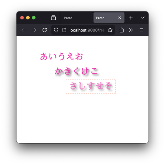
なんで、指定していないのに「さしすせそ」にまで影がついてくるんだろう?「かきくけこ」もフォント指定していないけどなぁ、と首をかしげてたんだけど。 …なるほど。 Canvas のコンテストオブジェクトのうち、「Canvas2D コンテキスト」は、1つだけということなのか、と。 以下のように、(ctx、ctx2 などなどと)変数をボコボコ作ってみたところで、見ているオブジェクト(Canvas2D コンテキスト)は同じモノ、ということだったのか、と。 ;;=================== (defn drawText [ctx text x y color w] (do (set! (.-fillStyle ctx) color) (.fillText ctx text x y w))) (defn drawText2 [ctx text x y color w] (do (set! (.-strokeStyle ctx) color) (.strokeText ctx text x y w))) ;;=================== (defn render7 [name] (let [canvas (.querySelector js/document.body name) ctx (.getContext canvas "2d") ctx2 (.getContext canvas "2d")] (set! (.-font ctx) "bold 30px cursive") (set! (.-textBaseline ctx) "alphabetic") (set! (.-textAlign ctx) "start") ;; 描画1 (drawText ctx "あいうえお" 50 50 "#ff00aa" 150) ;; 「影」についての情報 (set! (.-shadowBlur ctx2) 5) (set! (.-shadowColor ctx2) "#666666") (set! (.-shadowOffsetX ctx2) 5) (set! (.-shadowOffsetY ctx2) 5) ;; 描画2 (drawText ctx2 "かきくけこ" 100 100 "#ff00aa" 150) ;; 明示的に初期化しないと、前に設定した値が引き継がれる ;; (set! (.-shadowBlur ctx) 0) ;; (set! (.-shadowOffsetX ctx) 0) ;; (set! (.-shadowOffsetY ctx) 0) ;; 描画3 (drawText2 ctx "さしすせそ" 150 150 "#ff00aa" 150) ))
;;===================
0 notes
Text
Lưu ý với hàm drawText() trong Android
Ví dụ có đoạn khởi tạo như sau: textPaint = new TextPaint(); textPaint.setColor(Color.parseColor("#000000")); textPaint.setStyle(Paint.Style.FILL); textPaint.setTextAlign(Paint.Align.LEFT); textPaint.setAntiAlias(true); textPaint.setTextSize(33); Lưu ý: Paint.Align.LEFT sẽ xác định mỏ neo bên trái và vẽ từ bên trái vẽ sang tính từ điểm (x,y)Paint.Align.CENTER sẽ xác định mỏ neo ở giữa và vẽ từ…

View On WordPress
0 notes
Text
How to add Watermark on UIImage in swift
Learn Swift programming
Hello, Today we are going to learn how to add watermark(Text/ Sign) on UIImage. This is a simple way to add text in particular position. Implement this function in UIImage extension #01 Implement Add Text on Image // MARK: - Adding texts/ Water mark on image func addTextOnImage(drawText text: String, atPoint point: CGPoint? = nil) -> UIImage { let textColor = UIColor.white let textFont =…
View On WordPress
#Developer#Development#how to make an ios app#Ios#kathir#ktrkarthir#ktrkathir#swift#Tutorial#Tutorials#watermark#Xcode
0 notes
Text
Retro Gadgets Built In Font How to use

Welcome to our Retro Gadgets Built In Font How to use guide. Quick guide how to use the Built-In font and draw it to a screen (because the dev documentation is slightly wrong). #RetroGadgets
Retro Gadgets Built In Font How to use
Quick guide how to use the Built-In font and draw it to a screen (because the dev documentation is slightly wrong) How to use? In the developer provided documentation, it shows an incorrect way of calling the built in font. This is how it's actually done. In the pictures I've highlighted the code that we'll be using. Please disregard the rest of it as it's part of a project I'm working on. (feel free to use it if you want to though!) ------------------------------------------------------------------------------------------------------------------------------------ If you just want the built in font: local fontBasic = gdt.ROM.System.SpriteSheets ------------------------------------------------------------------------------------------------------------------------------------ You'll need a video chip assigned to the screen if you wish to draw to the screen. You'll also need a ROM chip installed. NOTE: Steps 1 and 2 will need to be placed ABOVE the update function. Step 3 will need to be placed INSIDE the update function (or whatever function you're using for the screen) Step 1: Code: - local vid = gdt.VideoChip0 "vid" can be named whatever you want. If you have more than one Video Chip you'll need to make sure it's the right one. Step 2: Code: - local fontBasic = gdt.ROM.System.SpriteSheets The "fontBasic" can be named whatever you want it to be.

Now, to draw it to a screen you simply do this (highlighted section)

Step 3: Code: - vid.DrawText(vid, vec2(0,0),fontBasic,"volume",color.red,color.blue) So first we call the Video Chip with vid. (or whatever you named it in Step 1). Then DrawText is the command to, well, draw text onto the screen. Inside the parentheses() you call the Video Chip with vid (or whatever you named it in Step 1). Then we choose where on the screen it will go with vec2(0,0). The numbers are X and Y co-ordinates. Since I want it in the top left, I simply put 0,0. Next we call the font of the text that we want. We'll just use the built in font by calling fontBasic (or whatever you named it in Step 2). Then we type out what we want to be displayed in " " For this example I just want it to say "volume" on the screen. Then we choose the color of the font, and lastly the color of the background. If your text is something that will update (a volume number for example) you'll want to make sure that it clears the old text before writing new text. Otherwise it will keep drawing over top of itself. This is simply done with:

Code: - vid.Clear(vid,color.blue) vid - Once again calling the Video Chip. .Clear - Clears the text. (vid,color.blue) - Calling the Video Chip (no idea why this has to be done twice) then a background color.

Now when we power it on we can see the red "volume" text being displayed in the top left of the screen with a blue background. Read the full article
0 notes
Text
Oxocard Galaxy - Teil 2 - programmieren in OxoScript

In diesem zweiten Teil zur Oxocard Galaxy möchte ich dir zeigen, wie du diese in dem online Editor OxoScript programmierst.

Oxocard Galaxy - Teil 2 - programmieren in OxoScript Im ersten Teil Oxocard Galaxy – Teil 1 – Einrichten habe ich dir bereits gezeigt, wie du diese Karte einrichtest und ein erstes kleines Programm auf dieses lädst. Ich gehe also hier davon aus, dass diese Karte bei dir bereits eingerichtet ist. Der Online-Editor OxoScript befindet sich derzeit in der BETA Version (Stand 22.10.2022) und daher kann es vorkommen, dass einige Punkte, welche ich hier anspreche / zeige ggf. entfallen oder an einer anderen Stelle später zu finden sind. https://youtu.be/jrIcdBIFvrg
Aufbau der Oberfläche von OxoScript
Du findest das Tool unter https://editor.oxoscript.com/ und kannst es ohne Anmeldung verwenden.

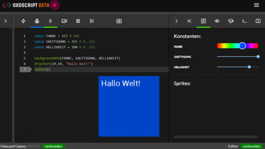
Oberfläche des Online-Editors OxoScript

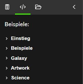
Toolbar für die Datei / Script Verwaltung Auf der Linken Seite findest du die Schaltflächen für - Meine Geräte, - Beispiele, - Meine Scripts, - Menü einklappen

Toolbar zum ausführen / debuggen von Code In der Mitte befindet sich der Bereich wo der Quellcode geschrieben / angezeigt wird und dort findest du ebenfalls eine Toolbar mit den Schaltflächen - Code ausführen, - Code debuggen, - Debug ausführen, - Beobachten, - Pause, - Schritt, - zum Breakpoint ausführen, - Bildschirmfoto aufnehmen

Toolbar mit nützlichen Tools für Hilfe/ Tutorials etc. Auf der rechten Seite findest du Tools, welche dir bei der Entwicklung helfen können - Konstanten, - Variablen, - Tutorial, - Terminal, - Dokumentation, sowie - die beiden Schaltflächen zum Erweitern / Einklappen des Menüs
Beispiele für die verschiedenen Karten
Du findest in diesem Tool eine Vielzahl von Beispielen zu jeder verfügbaren Karte. Wobei einige Beispiele für alle Karten funktionieren. Denn alle derzeit verfügbaren Modelle besitzen zumindest ein TFT Display.


Hilfe & Tutorials
Du findest auf der rechten Seite die beiden Schaltflächen, um zur offiziellen Dokumentation sowie zur Hilfe zu gelangen. Die Dokumentation ist sehr gut und du findest zu den Befehlen & Funktionen ein Beispiel, welches du durch einen kleinen Hyperlink kopieren und verwenden kannst. Es wird jedoch hier speziell auf die Eigenschaften der einzelnen Karten eingegangen, echte Tutorials zur Programmierung in Python findest du dort leider nicht, aber im Internet wirst du sicherlich findig.
Ein kleines Beispiel
Wollen wir zunächst ein kleines Beispiel programmieren, welches wir Stück-für-Stück ausbauen und benutzen wollen, um die verschiedenen Funktionen kennenzulernen. background(255,0,0) drawText(10,10, "Hallo Welt!") update() Es ist ein einfaches kleines "Hallo Welt!" wie man es bereits von diversen Beiträgen kennt, aber genau hier kann man so einiges machen, aber siehe gleich selber. Zunächst wollen wir die Hintergrundfarbe des Displays ändern, dazu fügen wir pro Feld in der Funktion "background" eine Konstante hinzu. Eigentlich gibt es in Python keine Konstanten, aber hier wurde die Programmiersprache deutlich aufgebohrt und dieses ist eines davon. const RED = 149 # 0..255 const GREEN = 0 # 0..255 const BLUE = 0 # 0..255 background(RED,GREEN,BLUE) drawText(10,10, "Hallo Welt!") update() Wenn eine Konstante wie nachfolgend deklariert wird (inkl. Kommentar) dann wird ein Slider erstellt, welcher von min. bis max. der Range, welche in dem Kommentar genannt wird erzeugt. const RED = 149 # 0..255 In meinem Fall habe ich pro Farbwert einen Slider und kann somit den RGB Wert bequem über die Slider einstellen.

Aber noch einfacher geht es natürlich mit einem Slider für Farben. const FARBE = 157 # HUE const SAETTIGUNG = 255 # 0..255 const HELLIGKEIT = 200 # 0..255 backgroundHSV(FARBE, SAETTIGUNG, HELLIGKEIT) drawText(10,10, "Hallo Welt!") update()
Eine boolesche Konstante erzeugt einen kleinen Schalter, welchen wir nutzen können, um bestimmten Code zu durchlaufen. const FARBE = 157 # HUE const SAETTIGUNG = 255 # 0..255 const HELLIGKEIT = 200 # 0..255 const SHOW_TEXT = true # true, false backgroundHSV(FARBE, SAETTIGUNG, HELLIGKEIT) if SHOW_TEXT: drawText(10,10, "Hallo Welt!") update() Read the full article
1 note
·
View note
Note
YOU WATCH DRAWTEXTIVES TOO?!?!?!! YESSSSSSS
AW YEAH I DO!!!! IT'S SO GOOD
1 note
·
View note
Text
FFmpeg Drawtext Filter for Overlays, Scrolling Text, Timestamps on Videos
https://ottverse.com/ffmpeg-drawtext-filter-dynamic-overlays-timecode-scrolling-text-credits/ Comments
0 notes
Video
youtube

custom writer
About me
Pdf Printer
Pdf Printer The PDF File Writer has a number of PdfContents methods supporting text annotation. The annotation space is a rectangle space defined by absolute coordinates relative to the bottom left corner of the page. To add an internet hyperlink call AddWebLink method of the PdfPage class. Therefore, the primary method above must encode the string from sixteen bit characters to byte array. The destination is outlined as a location marker. Location marker must have a novel name, a scope , and document location . NamedDest Scope can be used for either doc hyperlink or for named destination or each . Many links can point to the identical location marker. There are 5 strategies to outline a brush for all functions. The initial document show controls the appearance of your document when it is displayed by the PDF viewer . Adobe Acrobat viewer has navigation panels on the left side of the display. Adding a chart to a PDF doc is four steps course of. This step prompts bookmarks in your doc and returns the basis node. The OtherExample.cs supply code has an example of bookmarks. At one location there is a hierarchy of three levels. You can see the result in OtherExample.pdf file. Drawing web link within TextBox is a two step course of. First you add the textual content and the net link string to the field utilizing one of many AddText methods of TextBox class. Second you draw the TextBox to the page contents using one of the DrawText strategies of PdfContents. It will calculate font size based mostly on chart's resolution. The documentation for building a chart is past the scope of this text. Next you create a PdfChart from the Chart created above. The recommended method to create a chart is to use a static technique of PdfChart object. To view particular person glyph press view or double click. You can view the file with a textual content editor however you can't open it with PDF reader. The Test methodology below demonstrates the six steps described in the introduction for making a PDF file. The method might be executed whenever you press on the “Article Example” button of the demo program. The following subsections describe in detail each step. If a PDF document uses layers, the layers management switches might be displayed in this panel. The person can display or hide gadgets that had been connected to those layer controls. The PDF reference handbook has full description of permissions. For more information about named locations please discuss with Adobe PDF file specification “PDF Reference, Sixth Edition, Adobe Portable Document Format Version 1.7 November 2006”. Document links enable PDF doc customers to click on on the hyperlink and leap to a different a part of the document. All of those methods will set the brush opacity on the identical time. There are three strategies to outline a brush for WPF purposes. If System.Windows.Media reference just isn't available (i.e. your application is Windows Form), you have to add PresentationCore and WindowsBase assemblies to your software. They are calculated from the size in pixels and resolution of the chart. PdfChart has a CreateFont technique to simplify the creation of fonts.
0 notes
Note
okay last workflow question I promise. what options do you use to add text w ffmpeg? or is that a different post-processing step?
i’m going to be honest i don’t remember what most of this stuff does but here’s a generated command from my awful autogif.py:
C:/Users/█████████/Downloads/ffmpeg/bin/ffmpeg.exe -start_number 52 -framerate 25 -i "C:\Users\█████████\Videos\gifworkspace\thatwouldbeveryrude/0/%05d.png" -i "C:\Users\█████████\Videos\gifworkspace\thatwouldbeveryrude/0/palette.png" -lavfi "scale=-1:1080, crop=in_w-320:in_h, eq=contrast=1.04:saturation=1.2 ,hqdn3d, unsharp=5:5:1:3:3:0, drawtext="fontfile=/Windows/Fonts/Roboto-Medium.ttf:fontsize=80:text="That would be very rude":fontcolor=#F689BD:borderw=10:x=(w-text_w)/2:y=(h-90)-50",scale=540:-1, eq, drawtext="fontfile=/Windows/Fonts/consolab.ttf:fontsize=10:text="estufar":fontcolor=0xffffff60:bordercolor=0x00000060:borderw=1:x=3:y=h-12" [x]; [x][1:v] paletteuse=dither=sierra2" -y "C:\Users\█████████\Videos\gifworkspace\thatwouldbeveryrude/0.gif"
#i hope that this blob of a command helps#i also hope that the quote marks don't get converted into curly quotes#ffmpeg#nightpool
1 note
·
View note
Video
tumblr
This is a pretty simple terminal; it has a byte[], width, height, and byte color for drawing.
The byte color holds the background color index 0-15 in the high order bits (1111 0000) and the foreground color index 0-15 in the low order bits (0000 1111). When I do a DrawText(x,y,string) call, it just iterates the string, casts its char value to a byte, and copies the value in. Every other byte in the array holds a copy of the drawing color (which is a byte, above). Basically every text character is 2 bytes of data so its pretty lightweight.
Because it’s just plain old data in an array, I can poke values and change them randomly as seen in the video. If I want to change the background or text color, I just have to set the appropriate bits. It’s kind of cumbersome to fiddle with specific bits, though, but it’s possible to do so.
The big bottleneck comes from rendering the terminal itself. I kept the rendering completely separate from the display/writing to it. While it’s drawn to its own texture, I’m currently iterating the whole thing every frame (40x30). An improvement here would be to cache a number of display regions, then only redraw those parts to the texture; no display region updates means the texture isn’t updated, and only drawn to the main screen so it would be very fast in that case.
6 notes
·
View notes
Text
Прежде чем приступить к экспериментам, приведем основные функции класса Canvas для рисования графических примитивов. В таблице 3.12 приведены основные методы для рисования с помощью Canvas.
МетодНазначение
drawARGB()/drawRGB()/drawColor()Заполняет холст сплошным цветом
drawArc()Рисует дугу между двумя углами внутри заданной прямоугольной области
drawBitmap()Рисует растровое изображение на холсте
drawCircle()Рисует окружность с определенным радиусом вокруг заданной точки
drawLine(s)()Рисует линию (или последовательность линий) между двумя точками
drawOval()Рисует овал на основе прямоугольной области
drawPaint()Закрашивает весь холст с помощью заданного объекта Paint
drawPath()Рисует указанный контур, используется для хранения набора графических примитивов в виде единого объекта
drawPicture()Рисует объект Picture внутри заданного прямоугольника
drawPoint()Рисует точку в заданном месте
drawRect()Рисует прямоугольник
drawText()Рисует текстовую строку на холсте
rotate() и restore()Вращение холста
scale() и translate()Изменение и перемещение координатной системы
Табл. 3.12.
Более подробно с инструментами класса Canvas можно ознакомиться в офи��иальной документации.
Пример 3.7
Как было сказано выше, вся работа с графикой происходит в методе onDraw() класса. Для начала установим цвет холста, на котором будем рисовать, пусть это будет белый цвет. При желании можно установить любой другой.
Для этого сразу после строчки super.onDraw(canvas) напишем код:
Paint paint = new Paint(); // Выбираем кисть paint.setStyle(Paint.Style.FILL); // Белый цвет кисти paint.setColor(Color.WHITE); // Закрашиваем холст canvas.drawPaint(paint);
0 notes
Video
tumblr


Radar Sensor
Description of Project
The aim of this project is to create radar sensor which will provide red line pattern in the graphic when an object or human appears to the radar field of view. However, we can always make the sensor more usable by increasing the field of view. In this project, we have used 2cm field of view to show that the radar sensor is working. This device can detect anything in the room such as obstacles, Humans and object. On the other hand, servo motor turns 180 degrees from one side to another for detection.
Codes
#include<Servo.h>
int trigPin=2;
int echoPin=3;
long duration;
int distance;
Servo servo;
void setup()
{
pinMode(trigPin, OUTPUT);
pinMode(echoPin, INPUT);
Serial.begin(9600);
servo.attach(9);
}
void loop()
{
for(int i=15;i<=165;i++)
{
servo.write(i);
delay(100);
distance=calculateDistance();
Serial.print(i);
Serial.print(",");
Serial.print(distance);
Serial.print(".");
}
for(int i=165;i>15;i--)
{
servo.write(i);
delay(100);
distance=calculateDistance();
Serial.print(i);
Serial.print(",");
Serial.print(distance);
Serial.print(".");
}
}
int calculateDistance()
{
digitalWrite(trigPin,LOW);
delayMicroseconds(2);
digitalWrite(trigPin,HIGH);
delayMicroseconds(10);
digitalWrite(trigPin,LOW);
duration=pulseIn(echoPin,HIGH);
distance=duration*0.034/2;
return distance;
}
Processing
import processing.serial.*;
import java.awt.event.KeyEvent;
import java.io.IOException;
Serial myPort;
String angle="";
String distance="";
String data="";
String noObject;
float pixelsDistance;
int iAngle,iDistance;
int index1=0,index2=0;
PFont orcFont;
void setup()
{
size(1496,900);
smooth();
myPort=new Serial(this,"COM3",9600);
myPort.bufferUntil('.');
orcFont=loadFont("OCRAExtended-30.vlw");
}
void draw()
{
fill(98,245,31);
textFont(orcFont);
noStroke();
fill(0,4);
rect(0,0,width,1010);
fill(98,245,31);
drawRadar();
drawLine();
drawObject();
drawText();
}
void serialEvent(Serial myPort)
{
data=myPort.readStringUntil('.');
data=data.substring(0,data.length()-1);
index1=data.indexOf(",");
angle=data.substring(0,index1);
distance=data.substring(index1+1,data.length());
iAngle=int(angle);
iDistance=int(distance);
}
void drawRadar(){
pushMatrix();
translate(760,800);
noFill();
strokeWeight(2);
stroke(98,245,31);
arc(0,0,1400,1400,PI,TWO_PI);
arc(0,0,1100,1100,PI,TWO_PI);
arc(0,0,800,800,PI,TWO_PI);
arc(0,0,500,500,PI,TWO_PI);
line(-760,0,760,0);
line(0,0,-760*cos(radians(30)),-760*sin(radians(30)));
line(0,0,-760*cos(radians(60)),-760*sin(radians(60)));
line(0,0,-760*cos(radians(90)),-760*sin(radians(90)));
line(0,0,-760*cos(radians(120)),-760*sin(radians(120)));
line(0,0,-760*cos(radians(150)),-760*sin(radians(150)));
line(-760*cos(radians(30)),0,760,0);
popMatrix();
}
void drawObject() {
pushMatrix();
translate(760,800); // moves the starting coordinats to new location
strokeWeight(9);
stroke(255,10,10); // red color
pixelsDistance = iDistance*22.5; // covers the distance from the sensor from cm to pixels
// limiting the range to 40 cms
if(iDistance<40){
// draws the object according to the angle and the distance
line(pixelsDistance*cos(radians(iAngle)),-pixelsDistance*sin(radians(iAngle)),750*cos(radians(iAngle)),-750*sin(radians(iAngle)));
}
popMatrix();
}
void drawLine()
{
pushMatrix();
strokeWeight(9);
stroke(30,250,60);
translate(760,800);
line(0,0,750*cos(radians(iAngle)),-750*sin(radians(iAngle)));
popMatrix();
}
void drawText()
{
pushMatrix();
if(iDistance>40)
{
noObject="Out ofRange";
}
else{
noObject="In Range";
}
fill(0,0,0);
noStroke();
rect(0, 1010, width, 1080);
fill(98,245,31);
textSize(25);
text("10cm",1180,990);
text("20cm",1380,990);
text("30cm",1580,990);
text("40cm",1780,990);
textSize(30);
text("Object: " + noObject,15,100);
text("Angle: " + iAngle +" °",400, 50);
text("Distance: ", 13,50);
if(iDistance<40) {
text(" " + iDistance +" cm",30,50);
}
textSize(15);
fill(98,245,60);
translate(761+760*cos(radians(30)),782-760*sin(radians(30)));
rotate(-radians(-60));
text("30°",0,0);
resetMatrix();
translate(754+760*cos(radians(60)),784-760*sin(radians(60)));
rotate(-radians(-30));
text("60°",0,0);
resetMatrix();
translate(745+760*cos(radians(90)),790-760*sin(radians(90)));
rotate(radians(0));
text("90°",0,0);
resetMatrix();
translate(735+760*cos(radians(120)),803-760*sin(radians(120)));
rotate(radians(-30));
text("120°",0,0);
resetMatrix();
translate(740+760*cos(radians(150)),818-760*sin(radians(150)));
rotate(radians(-60));
text("150°",0,0);
popMatrix();
}
Components
· Arduino optional board
· Ultrasonic Sensor
· Servo motor
· Wires
Improvements
This project has significant amount of capacity for improvements. For instance, further improvements could including by increasing radar field of view, adding sound ( sensor will beep when radar detects anything in the room) and LED lights ( LED will light red when sensor detects anything, otherwise LED will light green).
References
Ultrasonic Ranging Using Arduino and Processing (2018) https://create.arduino.cc/projecthub/bharathrao64/ultrasonic-ranging-using-arduino-and-processing-radar-4091b4?ref=tag&ref_id=embedded&offset=13
Accessed on 10/04/18
0 notes
Text
Como criar um Radar com o Arduino? [Video]

Hoje vamos ver como podemos criar um fantástico Radar como nos filmes! O nosso componentes principal que nos vai permitir criar um radar será o Sensor de Distância Ultrasónico HC-SR04. Desta vez para criarmos o intarface animado em tempo real, vamos utilizar uma ferramenta nova o Processing. Podem fazer download e saber mais informações no site oficial: www.processing.org Mais uma vez vamos explicar como fazer este projeto. Abaixo poderão encontrar a lista de materiais utilizados, esquema de montagem e o código para o Arduino.
# Esquema de montagem:

# Código Utilizado no Arduino IDE:
#include . // Defines Tirg and Echo pins of the Ultrasonic Sensor const int trigPin = 10; const int echoPin = 11; // Variables for the duration and the distance long duration; int distance; Servo myServo; // Creates a servo object for controlling the servo motor void setup() { pinMode(trigPin, OUTPUT); // Sets the trigPin as an Output pinMode(echoPin, INPUT); // Sets the echoPin as an Input Serial.begin(9600); myServo.attach(12); // Defines on which pin is the servo motor attached } void loop() { // rotates the servo motor from 15 to 165 degrees for(int i=0;i0;i--){ myServo.write(i); delay(30); distance = calculateDistance(); Serial.print(i); Serial.print(","); Serial.print(distance); Serial.print("."); } } // Function for calculating the distance measured by the Ultrasonic sensor int calculateDistance(){ digitalWrite(trigPin, LOW); delayMicroseconds(2); // Sets the trigPin on HIGH state for 10 micro seconds digitalWrite(trigPin, HIGH); delayMicroseconds(10); digitalWrite(trigPin, LOW); duration = pulseIn(echoPin, HIGH); // Reads the echoPin, returns the sound wave travel time in microseconds distance= duration*0.034/2; return distance; }
# Código Utilizado no PROCESSING:
import processing.serial.*; // Importa as bibliotecas para comunicação de Seriew import java.awt.event.KeyEvent; // Importa as bibliotecas para ler a informação da entrada de serie import java.io.IOException; Serial myPort; // define o objeto Serial // define as variaveis String angle=""; String distance=""; String data=""; String noObject; float pixsDistance; int iAngle, iDistance; int index1=0; int index2=0; PFont orcFont; void setup() { size (1280, 720); // **Mudar isto para a sua resolução** smooth(); myPort = new Serial(this,"COM3", 9600); // Começa a comunicação Serie myPort.bufferUntil('.'); // Lê o Serial Monitor até ao ponto final orcFont = loadFont("OCRAExtended-30.vlw"); } void draw() { fill(98,245,31); textFont(orcFont); // Simula o movimento das linhas noStroke(); fill(0,4); rect(0, 0, width, height-height*0.065); fill(98,245,31); // green color // Chama as funções Radar, line, Object, Text drawRadar(); drawLine(); drawObject(); drawText(); } void serialEvent (Serial myPort) { // Começa a ler a informação de Serie // lê a informação de Serie até ao caracter '.', esta informação é atribuida a uma string chamada "data". data = myPort.readStringUntil('.'); data = data.substring(0,data.length()-1); index1 = data.indexOf(","); // angle= data.substring(0, index1); distance= data.substring(index1+1, data.length()); // Converte as variaveis string em Integer iAngle = int(angle); iDistance = int(distance); } void drawRadar() { pushMatrix(); translate(width/2,height-height*0.074); // Move as coordenadas iniciais para outro local noFill(); strokeWeight(2); stroke(98,245,31); // Desenha os semicirculos arc(0,0,(width-width*0.0625),(width-width*0.0625),PI,TWO_PI); arc(0,0,(width-width*0.27),(width-width*0.27),PI,TWO_PI); arc(0,0,(width-width*0.479),(width-width*0.479),PI,TWO_PI); arc(0,0,(width-width*0.687),(width-width*0.687),PI,TWO_PI); // Desenha as linhas dos angulos line(-width/2,0,width/2,0); line(0,0,(-width/2)*cos(radians(30)),(-width/2)*sin(radians(30))); line(0,0,(-width/2)*cos(radians(60)),(-width/2)*sin(radians(60))); line(0,0,(-width/2)*cos(radians(90)),(-width/2)*sin(radians(90))); line(0,0,(-width/2)*cos(radians(120)),(-width/2)*sin(radians(120))); line(0,0,(-width/2)*cos(radians(150)),(-width/2)*sin(radians(150))); line((-width/2)*cos(radians(30)),0,width/2,0); popMatrix(); } void drawObject() { pushMatrix(); translate(width/2,height-height*0.074); // Move as coordenadas iniciais para outro local strokeWeight(9); stroke(255,10,10); // red color pixsDistance = iDistance*((height-height*0.1666)*0.025); // cobre a distancia entre o sensor e o objeto // limiting the range to 40 cms if(iDistance40) { noObject = "Out of Range"; } else { noObject = "In Range"; } fill(0,0,0); noStroke(); rect(0, height-height*0.0648, width, height); fill(98,245,31); textSize(25); text("10cm",width-width*0.3854,height-height*0.0833); text("20cm",width-width*0.281,height-height*0.0833); text("30cm",width-width*0.177,height-height*0.0833); text("40cm",width-width*0.0729,height-height*0.0833); textSize(40); text("Object: " + noObject, width-width*0.875, height-height*0.0277); text("Angle: " + iAngle +" °", width-width*0.48, height-height*0.0277); text("Distance: ", width-width*0.26, height-height*0.0277); if(iDistance Read the full article
0 notes