#embeddedsystem esp32
Explore tagged Tumblr posts
Visit Tumblr Blog
Explore Tumblr blogs with no restrictions, modern design and the best experience.
Last Seen Tumblr Blogs


Fun Fact
Tumblr is available in 18 languages.
Text
ESP32 ItsyBitsy is in final testing zOne!
OK, after a long hiatus, the ESP32 Itsy Bitsy prototypes are built and ready for testing! We first designed this board Feb 20, 2020 - and it's been waiting oh so patiently for its turn. The ESP32 Pico module packs 8 MB of flash and 2 MB of PSRAM. Despite its small size this board can handle fairly complex programs. This board is very small but has lots of pins, with a USB-serial converter, NeoPixel, reset and user button, Stemma QT connector, and a 5V-logic output specifically for driving NeoPixels. to do my final 'all in one' test we're reading temperature and humidity from an I2C sensor, sending it to IO, then reading back the onboard NeoPixel color from the dashboard. It's an excellent way to make sure the whole thing is working the way we like. Last up, we'll do a low-power test, and then it'll be ready for fabrication!
#espressif#esp32#adafruit#ItsyBitsy#NeoPixel#hardwaretesting#pcbdesign#micropython#iotprojects#embeddedsystems#prototyping#makersmovement#technologyinnovation#electronicengineering#diyelectronics
8 notes
·
View notes
Text
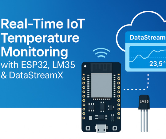
Building a Real-Time IoT Temperature Monitoring System with ESP32, LM35 & DataStreamX
In a world driven by smart technology, real-time data monitoring has become essential — not just in industrial systems, but even in basic IoT applications like temperature sensing.
This post shows you how to build a complete IoT data pipeline using:
📟 ESP32 microcontroller
🌡️ LM35 temperature sensor
☁️ Cloudtopiaa’s DataStreamX — a powerful real-time data streaming engine
Whether you’re a beginner in IoT development or exploring edge computing for enterprise systems, this guide blends hardware, firmware, and cloud data streaming into one cohesive solution.
Project Overview: What We’re Building
We’ll build a real-time IoT system that:
Reads temperature using an LM35 sensor
Transmits it via MQTT protocol
Processes the data using DataStreamX (on Cloudtopiaa’s infrastructure)
Displays it on a live IoT dashboard
Use Cases: Industrial IoT Environmental monitoring Smart homes Embedded systems requiring real-time response
Components Required
ComponentDescriptionESP32 BoardWi-Fi-enabled microcontroller for IoTLM35 Temperature SensorAnalog sensor with linear outputJumper WiresFor connectionsBreadboardFor prototypingDataStreamX PlatformReal-time streaming and visualization
Hardware Setup
Connect LM35 to ESP32:
VCC → 3.3V
GND → GND
VOUT → Analog pin (e.g., GPIO34)
Power up your ESP32
Firmware: Code for ESP32
The ESP32 will:
Read analog voltage from the LM35 sensor
Convert it into Celsius
Publish the readings to DataStreamX every 5 seconds using MQTT
temperature = (analogRead(34) * 3.3 / 4095.0) * 100.0; // LM35 conversion
What is DataStreamX?
DataStreamX is a low-code, real-time data pipeline platform built into Cloudtopiaa’s cloud infrastructure. It helps developers to build resilient, scalable IoT systems easily.
Key Features:
MQTT Adapter for IoT sensors
Real-time dashboards
Event-based alerts
Edge-cloud synchronization
Secure data routing
Cloudtopiaa + DataStreamX = Instant, Scalable IoT
Setting Up DataStreamX on Cloudtopiaa
To set it up:
Log into: https://cloudtopiaa.com
Go to the DataStreamX dashboard
Create a new MQTT Adapter
Define:
Input Stream: Temperature sensor topic
Logic: (e.g., Trigger an alert if temp > 40°C)
Output Stream: Live dashboard visualization
Live Visualization: Monitor in Real-Time
Once your ESP32 starts publishing:
View real-time temperature plots
Monitor averages, minimum, and maximum values
Visualize it instantly on the Cloudtopiaa dashboard
Bonus: Trigger Smart Actions
You can create rules like:
If temperature > 50°C → Send an email alert
If temperature > 60°C → Automatically activate a cooling fan
Security & Scalability
Cloudtopiaa ensures:
🔒Encrypted communication
🔑 Role-based access control
🧾 Audit logs for compliance
📈 Scalability from 10 to 10,000+ sensors
Perfect for smart factories, research labs, and large-scale IoT deployments!
Real-World Applications
Smart Homes: Thermal alerts & automation Healthcare IoT: Patient room temperature monitoring Environmental Monitoring: Greenhouses & weather stations Industry 4.0: Machine cooling and predictive maintenance Education: STEM IoT projects with ESP32
What’s Next? Intelligent Automation
Cloudtopiaa is working to add AI feedback loops inside DataStreamX soon, enabling:
Predict overheating events
Auto-adjust environmental controls
Optimize energy consumption in real-time
Start Your IoT Journey Today
You don’t have to be a cloud architect or hardware expert to create an IoT system today. With Cloudtopiaa’s low-code dashboard, you can:
Connect your devices
Set data logic
Visualize everything in real-time!
Build with DataStreamX → Start Now
#IOT#TemperatureMonitoring#ESP32#LM35#RealTimeData#DataStreamX#Cloudtopiaa#SmartTechnology#EdgeComputing#IoTProjects#EmbeddedSystems#MQTT
0 notes
Text
ESP32-WROOM-32: The Tiny Powerhouse for Your Next IoT Project! 🚀🔧
Looking for a microcontroller that packs a punch? The ESP32-WROOM-32 is your best bet! 💡 This Wi-Fi + Bluetooth-enabled module is perfect for IoT, robotics, and home automation. With its dual-core processor, low power consumption, and tons of GPIO pins, it's a maker's dream. Whether you're building a smart gadget or diving into edge computing, this little beast can handle it all!
🔥 Why choose ESP32-WROOM-32? ✅ Dual-core performance ✅ Built-in Wi-Fi & Bluetooth ✅ Low power consumption ✅ Tons of connectivity options
What cool projects are you making with it? Let’s discuss! 🛠️✨ #ESP32 #IoT #DIYTech
#ESP32#Microcontroller#IoT#EmbeddedSystems#ESP32WROOM32#Electronics#DIYProjects#Arduino#WiFiModule#Bluetooth#SmartDevices#HomeAutomation#ESP32Projects#Tech#CircuitDesign
0 notes
Text
Micropython - Adjusting for Daylight Savings and Updating the RTC of the SBC
A simple micropython function to adjust the time for DST.
So you are using ‘ntptime.settime()’ in Micropython to update the time in your script for whatever purpose you are using it for and you want to adjust for Daylight Savings. Micropython doesn’t support in the ntptime module handling that automatically, so here is a short work around to adjust the time appropriately for your RTC. Here’s my time sync function that I use, it’s pretty self…
#embedded-development#embeddedsystems#ESP32#learn-application-development#micropython#programming#Raspberry Pi#software-development
0 notes
Text
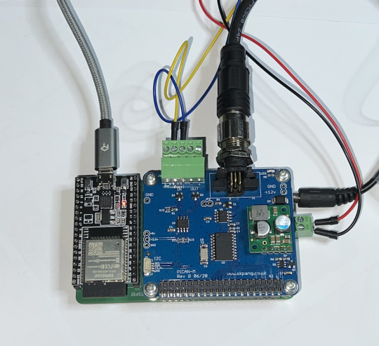
ESP32 with NMEA 2000 & NMEA 0183 Port
In this post I will describe the communication between the espBerry board with the integrated PICAN-M HAT. Due to the nature of the HAT, there are two sections: 1. The NMEA 0183 port and sketch and 2. the NMEA 2000 port and sketch.
1 note
·
View note
Text
Setting Up a Web Server on ESP32
This time we gonna set up a web server on ESP32 to control output that is 2 external LEDs.
Our goal is to control those LEDs only with giving simple switch input via web browser we have opened in device connected within the same network as the ESP32.
Things we need:
ESP32 ( NodeMCU-32S dev board used in this project)
2 LEDs
2 330 ohm resistors
Breadboard
Jumper wires

source: https://randomnerdtutorials.com/esp32-web-server-arduino-ide/
Connect all of those like the schematic shown above.
This is what it looks like on ours.
Therefore, you can open ArduinoIDE and setup code like this.

/********* Rui Santos Complete project details at http://randomnerdtutorials.com *********/ // Load Wi-Fi library #include <WiFi.h> // Replace with your network credentials const char* ssid = ""; const char* password = ""; // Set web server port number to 80 WiFiServer server(80); // Variable to store the HTTP request String header; // Auxiliar variables to store the current output state String output26State = "off"; String output27State = "off"; // Assign output variables to GPIO pins const int output26 = 26; const int output27 = 27; void setup() { Serial.begin(115200); // Initialize the output variables as outputs pinMode(output26, OUTPUT); pinMode(output27, OUTPUT); // Set outputs to LOW digitalWrite(output26, LOW); digitalWrite(output27, LOW); // Connect to Wi-Fi network with SSID and password Serial.print("Connecting to "); Serial.println(ssid); WiFi.begin(ssid, password); while (WiFi.status() != WL_CONNECTED) { delay(500); Serial.print("."); } // Print local IP address and start web server Serial.println(""); Serial.println("WiFi connected."); Serial.println("IP address: "); Serial.println(WiFi.localIP()); server.begin(); } void loop(){ WiFiClient client = server.available(); // Listen for incoming clients if (client) { // If a new client connects, Serial.println("New Client."); // print a message out in the serial port String currentLine = ""; // make a String to hold incoming data from the client while (client.connected()) { // loop while the client's connected if (client.available()) { // if there's bytes to read from the client, char c = client.read(); // read a byte, then Serial.write(c); // print it out the serial monitor header += c; if (c == '\n') { // if the byte is a newline character // if the current line is blank, you got two newline characters in a row. // that's the end of the client HTTP request, so send a response: if (currentLine.length() == 0) { // HTTP headers always start with a response code (e.g. HTTP/1.1 200 OK) // and a content-type so the client knows what's coming, then a blank line: client.println("HTTP/1.1 200 OK"); client.println("Content-type:text/html"); client.println("Connection: close"); client.println(); // turns the GPIOs on and off if (header.indexOf("GET /26/on") >= 0) { Serial.println("GPIO 26 on"); output26State = "on"; digitalWrite(output26, HIGH); } else if (header.indexOf("GET /26/off") >= 0) { Serial.println("GPIO 26 off"); output26State = "off"; digitalWrite(output26, LOW); } else if (header.indexOf("GET /27/on") >= 0) { Serial.println("GPIO 27 on"); output27State = "on"; digitalWrite(output27, HIGH); } else if (header.indexOf("GET /27/off") >= 0) { Serial.println("GPIO 27 off"); output27State = "off"; digitalWrite(output27, LOW); } // Display the HTML web page client.println("<!DOCTYPE html><html>"); client.println("<head><meta name=\"viewport\" content=\"width=device-width, initial-scale=1\">"); client.println("<link rel=\"icon\" href=\"data:,\">"); // CSS to style the on/off buttons // Feel free to change the background-color and font-size attributes to fit your preferences client.println("<style>html { font-family: Helvetica; display: inline-block; margin: 0px auto; text-align: center;}"); client.println(".button { background-color: #4CAF50; border: none; color: white; padding: 16px 40px;"); client.println("text-decoration: none; font-size: 30px; margin: 2px; cursor: pointer;}"); client.println(".button2 {background-color: #555555;}</style></head>"); // Web Page Heading client.println("<body><h1>ESP32 Web Server</h1>"); // Display current state, and ON/OFF buttons for GPIO 26 client.println("<p>GPIO 26 - State " + output26State + "</p>"); // If the output26State is off, it displays the ON button if (output26State=="off") { client.println("<p><a href=\"/26/on\"><button class=\"button\">ON</button></a></p>"); } else { client.println("<p><a href=\"/26/off\"><button class=\"button button2\">OFF</button></a></p>"); } // Display current state, and ON/OFF buttons for GPIO 27 client.println("<p>GPIO 27 - State " + output27State + "</p>"); // If the output27State is off, it displays the ON button if (output27State=="off") { client.println("<p><a href=\"/27/on\"><button class=\"button\">ON</button></a></p>"); } else { client.println("<p><a href=\"/27/off\"><button class=\"button button2\">OFF</button></a></p>"); } client.println("</body></html>"); // The HTTP response ends with another blank line client.println(); // Break out of the while loop break; } else { // if you got a newline, then clear currentLine currentLine = ""; } } else if (c != '\r') { // if you got anything else but a carriage return character, currentLine += c; // add it to the end of the currentLine } } } // Clear the header variable header = ""; // Close the connection client.stop(); Serial.println("Client disconnected."); Serial.println(""); } }
Source : https://raw.githubusercontent.com/RuiSantosdotme/ESP32-Course/master/code/WiFi_Web_Server_Outputs/WiFi_Web_Server_Outputs.ino
Do not forget to replace the SSID and password with your own network credentials.
After that upload the code to the board, and open serial monitor immediately as the code has been succesfully uploaded to the board.

We can access the web server from IP address shown on serial monitor. That time, ours were 192.168.43.226 . Thus from web browser we can open that IP address to open the LED controller dashboard. It going to be like graphics show below.

Hope this post useful for you guys.
Me right here signing out.
Ooh sorry, i forgot a thing. There is one more thing....
I have to tell you guys about this.
At the time I wrote this, in Indonesia currently we have COVID-19 pandemic and that make us ITB students to study from home. My colleagues in this project are Hardy and Abbel and we are separated while we don’t have complete module. Thus to solve this problem we collaborate online. Each of us doing things that we can do by ourself and we share it to make the project complete.
I hope that this pandemic can be away as fast as possible.
0 notes
Video
instagram
#esp32 and #bc24 at work in #palm springs. Worlds best night light! #wifi enabled. #switchdoclabs #makersgonnamake #science #embeddedsystems #stem https://www.instagram.com/p/BsUIVEZnRSJ/?utm_source=ig_tumblr_share&igshid=1b3c6y30eynr2
2 notes
·
View notes
Photo

Photo without effects. 🙋 This is not mini computer, it is just a good nema17 tmc2130 stepper motor driver with feedback. MORE JOKES, WIN'S AND FAIL'S 👉 @aelmaker #diyhome #diytutorial #iotdevices #iotsolutions #diyelectronics #embeddedsystem #aelmaker #electronics #nema #drivers #electronics #esp32 #m5stack @m5stack (Boka Chika Karibian) https://www.instagram.com/p/CSIKhNSjCp1/?utm_medium=tumblr
#diyhome#diytutorial#iotdevices#iotsolutions#diyelectronics#embeddedsystem#aelmaker#electronics#nema#drivers#esp32#m5stack
0 notes
Photo

Tiny Machine Learning (TinyML) is the latest embedded software technology that moves hardware into that almost magical realm, where machines can automatically learn and grow through use, like a primitive human brain. TinyML as the latest trend in building product intelligence. Arduino, the company best known for open-source hardware is making TinyML available for millions of developers. Together with Edge Impulse, they are turning the ubiquitous Arduino board into a powerful embedded ML platform, like the Arduino Nano 33 BLE Sense and other 32-bit boards. With this partnership you can run powerful learning models based on artificial neural networks (ANN) reaching and sampling tiny sensors along with low-powered microcontrollers. - - Source: Techcrunch - - #machinelearning #ml #arduino #arduinonano #arduinouno #arduino #embedded #iot #sensor #nodemcu #tinyml #esp32 #stm32 #sbc #electronics #developmentboard #raspberrypi #raspberrypi4 #fpga #zigbee #embeddedsystems #raspberrypi3 https://www.instagram.com/p/CBH5LKSn2RC/?igshid=1b1bqjdtz6l3x
#machinelearning#ml#arduino#arduinonano#arduinouno#embedded#iot#sensor#nodemcu#tinyml#esp32#stm32#sbc#electronics#developmentboard#raspberrypi#raspberrypi4#fpga#zigbee#embeddedsystems#raspberrypi3
0 notes
Photo
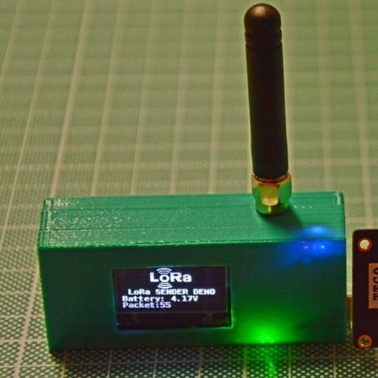
The second part of the article about the @ttgo_by_lilygo #TTGO #LORA32 is arrived! In this article there is a *complete* working example. #sourcecode is about a point-to-point #lora communication but with some extra features added letting anyone use the full capabilities of this board: both transmitter and receiver do a log file on the #sdcard If attached and the #battery voltage is monitored. I've explained all the issues about the usage of the two user-available SPI peripherals and about the battery/USB/external power usage. Thanks to #digitspace for giving me those board to experiment with. Read the full article in the bio. You must had read the previous article in order to understand perfectly: it's linked in the article you can reach from the bio. . . . . . . . . . . . . #wireless #esp32 #esp8266 #espressif #wifi #lorawan #lpwan #sigfox #loraalliance #semtech #arduinoide #smarthome #iot #automation #homeautomation #3dprinting #domotica #embeddedsystems #maker #coding #programmer https://www.instagram.com/p/CC-p2nZqPC9/?igshid=zoffk7v5mdmc
#ttgo#lora32#sourcecode#lora#sdcard#battery#digitspace#wireless#esp32#esp8266#espressif#wifi#lorawan#lpwan#sigfox#loraalliance#semtech#arduinoide#smarthome#iot#automation#homeautomation#3dprinting#domotica#embeddedsystems#maker#coding#programmer
0 notes
Text
Understanding ESP32 Pin Configuration: A Developer's Guide
The ESP32 microcontroller has become a cornerstone of IoT development, thanks to its versatility and powerful features. One of the most crucial aspects of working with ESP32 is understanding its pin configuration and capabilities. Let's dive into the essential aspects of ESP32 pins that every developer should know.

GPIO Pins Overview
The ESP32 boasts up to 34 GPIO (General Purpose Input/Output) pins, but not all are available for use in most development boards. Some key points about ESP32 pins:
GPIO 6-11: Reserved for internal SPI flash connection
GPIO 34-39: Input-only pins with no internal pull-up/pull-down resistors
ADC Capabilities: Two 12-bit SAR ADCs, supporting 18 measurement channels
Touch Sensors: Up to 10 capacitive touch GPIOs
Special Function Pins
Several pins serve dual purposes or have specific functions:
Boot Mode Pins GPIO 0: Bootloader mode when pulled low during reset GPIO 2: Connected to on-board LED in many development boards
UART Pins GPIO 1 (TX) and GPIO 3 (RX): Default UART0 communication Often used for flashing and debugging
SPI Pins VSPI: GPIO 5 (CS), 18 (CLK), 19 (MISO), 23 (MOSI) HSPI: GPIO 14 (CLK), 12 (MISO), 13 (MOSI), 15 (CS)
Best Practices for Pin Usage
Strapping Pins Always check the strapping pin status before using GPIO 0, 2, 4, 5, 12, and 15. These pins may affect boot behavior if incorrectly configured.
Input-Only Pins When designing sensor interfaces, prefer GPIO 34-39 for analog inputs as they're input-only and less susceptible to noise.
Pull-up/Pull-down Configuration
ADC Usage ADC1: Can be used with Wi-Fi/Bluetooth active ADC2: Only available when Wi-Fi/Bluetooth is disabled
Common Pitfalls to Avoid
Don't use GPIO 6-11 in your projects as they're connected to the internal SPI flash.
Avoid using strapping pins for critical functions that can't be changed during boot.
Remember that GPIO 34-39 don't have internal pull-up/pull-down resistors.
Be cautious with voltage levels - ESP32 pins operate at 3.3V.
Conclusion
Understanding ESP32 pinout is fundamental for successful project development. By following these guidelines and best practices, you can avoid common issues and make the most of your ESP32's capabilities. Remember to always consult the official ESP32 technical reference manual for detailed specifications and updates.
#ESP32 #PinConfiguration #DevelopersGuide #Microcontrollers #EmbeddedSystems #IoT #Programming #Hardware #Electronics #Arduino #ESP32S2 #ESP32C3 #ESP32C2 #ESP32C6 #ESP32S3 #ESP32H2 #ESP32P1
#ESP32#microcontroller#pinconfiguration#GPIO#ADC#DAC#I2C#SPI#UART#PWM#analog#digital#input#output#microcontrollers#embeddedsystems#IoT#InternetOfThings#electronics#hardware#software#programming#development#Arduino#ESP8266#RaspberryPi#microcontrollerprogramming#embeddedprogramming#IoTdevelopment#electronicdesign
1 note
·
View note
Text
Micropython - Adjusting for Daylight Savings and Updating the RTC of the SBC
A simple micropython function to adjust the time for DST.
So you are using ‘ntptime.settime()’ in Micropython to update the time in your script for whatever purpose you are using it for and you want to adjust for Daylight Savings. Micropython doesn’t support in the ntptime module handling that automatically, so here is a short work around to adjust the time appropriately for your RTC. Here’s my time sync function that I use, it’s pretty self…
#embedded-development#embeddedsystems#ESP32#learn-application-development#micropython#programming#Raspberry Pi#software-development
0 notes
Text

IoT ESP32 tutorial now available in imakestudio electronics
Download now in play store: https://tinyurl.com/ybqayjyf.
#arduinouno #arduino #robot #robotics #microcontroller #diyprojects #diyelectronics #diy #electronicsprojects #electronics #engineering #electricalprojects #iotprojects #iot #makerfaire #embeddedsystems #bot #ai #instadaily #follow #likeforlikes #follow4followback #esp32
0 notes
Text
ESP32 ❤️ LCD ❤️ Bluetooth Serial
Di post yang lalu kita telah berhasil menampilkan input dari serial monitor Arduino IDE ke LCD via mikrokontroler ESP32. Kali ini kita akan mencoba tantangan baru. Masih dengan perangkat yang sama, namun ada sesuatu yang berbeda. Dari yang sebelumnya input dari serial monitor, kini akan menerima input dari mesin Linux secara serial via bluetooth.
Yang kita butuhkan untuk proyek kali ini.
ESP32 (Node MCU 32S)
MicroUSB to USB cable
LCD Display
Jumper Cable
Linux/ PC/ ponsel android yang bisa menerima koneksi bluetooth serial
Pada kesempatan kali ini kami mencoba untuk menghubungkannya dengan komputer ber OS Linux (Ubuntu). Sebenarnya hal itu sangat sulit untuk dilakukan. Ada cerita dibalik proses berdarah-darah itu yang lengkapnya bisa dilihat di blog teman saya Hardy di pranala berikut https://medium.com/@18218004/devlog-7-lcd-and-bluetooth-12317838f583 . Dengan tweaknya kami berhasil mengirimkan input via terminal Ubuntu.
Dengan rangkaian yang sama dengan proyek di pranala ini https://hudanwidzamil.tumblr.com/post/190869474954/esp32-lcd . Kita bisa menggunakan kode seperti berikut yang merupakan hasil tweak untuk mengatasi hal-hal yang belum ada sebelumnya.
#include "BluetoothSerial.h" #include <LiquidCrystal_I2C.h> #if !defined(CONFIG_BT_ENABLED) || !defined(CONFIG_BLUEDROID_ENABLED) #error Bluetooth is not enabled! Please run `make menuconfig` to and enable it #endif int lcdColumns = 16; int lcdRows = 1; BluetoothSerial SerialBT; LiquidCrystal_I2C lcd(0x27, lcdColumns, lcdRows); String message = ""; char incomingChar; void setup() { lcd.init(); lcd.backlight(); Serial.begin(115200); SerialBT.begin("ESP32HardyHudanAbbel"); //Bluetooth device name } void loop() { if (SerialBT.available()){ char incomingChar = SerialBT.read(); if (incomingChar != '\n'){ lcd.clear(); message += String(incomingChar); } else { message = ""; } lcd.setCursor(0, 0); lcd.print(message); delay(20); } }
Setelah itu koneksikan dan pasangkan bluetooth pada esp32 dengan perangkat yang akan mengirim data serial.
Dengan komputer linux dan jerih payah yang dilakukan maka dapat dilihat hasil sebagai berikut

Hasil dapat berbeda jika ESP32 dikoneksikan dengan ponsel Android dengan aplikasi Serial Bluetooth Terminal..
Me here signing out once again
0 notes
Video
youtube
This channel is your #1 source for IoT, Voice AI, Embedded Systems, Bloc...
0 notes
Text
Micropython - Adjusting for Daylight Savings and Updating the RTC of the SBC
So you are using ‘ntptime.settime()’ in Micropython to update the time in your script for whatever purpose you are using it for and you want to adjust for Daylight Savings. Micropython doesn’t support in the ntptime module handling that automatically, so here is a short work around to adjust the time appropriately for your RTC. Here’s my time sync function that I use, it’s pretty self…
#embedded-development#embeddedsystems#ESP32#learn-application-development#micropython#programming#Raspberry Pi#software-development
0 notes