#exporting DWG to PDF
Explore tagged Tumblr posts
Visit Tumblr Blog
Explore Tumblr blogs with no restrictions, modern design and the best experience.
Last Seen Tumblr Blogs


Fun Fact
Tumblr posted its first advertisements in May 2012 and subsequently earned $13M in revenue.
Text
The Lifecycle of a Patent Drawing: From Concept to Filing
Patent drawings are an indispensable part of a successful patent application. Whether you’re applying for a utility patent to protect functionality or a design patent to protect appearance, drawings help communicate your invention in a way that words alone cannot. But what’s the journey like from initial concept to the final version that’s submitted to a patent office?
In this article, we’ll walk through the complete lifecycle of a patent drawing, from the first sketch to the final, legally compliant illustration that supports your patent claim.
1. Conceptualising the Invention
Every patent drawing begins with a core idea: the invention itself. This is the stage where inventors:
Define the invention’s purpose and functionality
Identify its unique elements
Consider how to visually represent these features
At this point, inventors might use rough hand-drawn sketches, photos of prototypes, or digital mockups. These early visuals serve as a blueprint for the professional drafts that follow.
2. Gathering Reference Materials
Before engaging a patent drawing service, inventors or patent attorneys compile all necessary reference materials, such as:
Hand sketches or digital renderings
Engineering diagrams or CAD files
Product photos or 3D models
Notes about key features or moving parts
The more detailed and organised this material is, the more accurate and efficient the drawing process will be.
3. Choosing the Right Drawing Type
There are two major types of patent drawings, and the process varies slightly depending on the one you’re preparing:
Utility Patent Drawings: These focus on how the invention works. Views often include cutaways, cross-sections, and exploded diagrams.
Design Patent Drawings: These focus on how the invention looks. Multiple perspective views (top, bottom, front, rear, left, right, and isometric) are typically required.
Determining which type you're filing for helps define the visual approach, level of detail, and drawing style needed.
4. Hiring a Professional Patent Drawing Service
While some inventors attempt to create patent drawings themselves, most rely on professionals for a few good reasons:
Compliance with USPTO, EPO, or WIPO guidelines
Technical drawing expertise
Knowledge of required line weights, margins, labelling, and formatting
Professional illustrators use software such as AutoCAD, Adobe Illustrator, SolidWorks, or CorelDRAW to produce high-precision, legally compliant drawings.
5. Drafting the Initial Illustrations
The first formal version of the patent drawing is created based on the materials provided and in consultation with the inventor or patent attorney. This initial draft typically includes:
All required views (perspective, sectional, exploded, etc.)
Annotations or labels as needed
Appropriate line styles (solid, dashed, broken) to represent different features
This stage focuses on accuracy and completeness, with the goal of visually representing the invention in its entirety.
6. Review and Revisions
After the initial drawings are delivered, the inventor or attorney reviews them carefully to:
Ensure all features are represented correctly
Check compliance with patent office requirements
Request revisions or additional views if needed
Most professional services offer at least one or two free revision rounds. This collaborative phase ensures that the drawing effectively supports the written claims and specification.
7. Finalisation and Formatting
Once approved, the drawings are finalised. This step involves:
Applying consistent line thickness and shading
Adding proper figure numbers and labels
Ensuring spacing, margins, and dimensions meet submission standards
Exporting in correct formats (e.g., PDF, TIFF, DWG)
At this stage, the drawing is ready for submission and is often integrated into the patent application package by the patent attorney.
8. Submission with the Patent Application
The completed patent drawings are submitted alongside the patent specification and claims to the relevant patent office. Depending on the jurisdiction, the drawings must:
Be printed on specific paper sizes (like A4 or letter)
Include identification data (inventor name, application number)
Be in black and white, unless colour is explicitly requested and justified
Compliance at this stage is crucial; non-compliant drawings can lead to office actions, delays, or outright rejection.
9. Post-Filing Updates or Revisions (If Needed)
Sometimes, the patent examiner may request changes or clarifications after reviewing the application. This may include:
Adding new views
Correcting labelling errors
Enhancing clarity or removing unnecessary details
In such cases, updated drawings must be submitted promptly and in the same compliant format.
In a Nutshell
The lifecycle of a patent drawing is a structured, collaborative, and highly technical process. What starts as a rough sketch or idea must be transformed into a professional, legally acceptable illustration that supports the core of your patent claims.
Understanding this process ensures fewer delays, better compliance, and a stronger patent application for first-time inventors and seasoned professionals alike. Investing in high-quality patent drawing services can make all the difference between rejection and protection.
0 notes
Text
VeryUtils DWG to PDF Converter SDK for Developers Royalty Free
VeryUtils DWG to PDF Converter SDK for Developers Royalty Free.
https://veryutils.com/dwg-to-pdf-converter-sdk
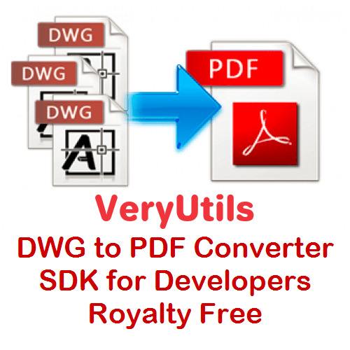
VeryUtils AutoCAD DWG to PDF Converter SDK is a DWG, DXF and DWF to PDF Conversion DLL Library for Developers. You can use it to convert DWG to PDF, DXF to PDF and DWF to PDF directly without the need for AutoCAD. This software swiftly and effortlessly converts DWG, DXF and DWF files into high-quality PDF files. VeryUtils DWG to PDF Converter SDK is a SDK that you can integrate it into your software for redistribution after purchasing the royalty-free license.
VeryUtils DWG to PDF Converter SDK provides you with flexibility and robust functionality to convert DWG, DXF and DWG files to PDF files on the fly. It's the best SDK software for converting AutoCAD files to PDF files on server and client systems. AutoCAD VeryUtils DWG to PDF Converter SDK is a control component that allows you to convert DWG to PDF, DXF to PDF, and DWF to PDF directly, without requiring AutoCAD.
✅ VeryUtils DWG to PDF Converter SDK Key Features:
Convert thousands of files while maintaining folder structure.
Batch combine multiple DWG files into a single PDF (requires PDF Split-Merge Software).
Create a .bat file to reuse conversion settings.
Send prompts directly within the SDK environment.
Stand-alone software; AutoCAD is NOT required.
Supports all versions of AutoCAD DWG, DXF, DWF files.
PDF encryption and password protection.
Supports SDK operation; you can call it from a script or your application.
Batch conversion supported; you can call it from a .bat file.
Supports all Windows systems, including both 32-bit and 64-bit systems.
Convert all DWG and DXF files to PDF files in a folder and its sub-folders recursively with one SDK.
Support for all versions of DWG, DXF and DWF formats.
Set page size directly or choose predefined sizes quickly.
Support for AutoCAD pen sets file (*.ctb).
Automatically adjust output paper size with layout settings.
Export layer and raster image objects to PDF.
Support for 3D objects hidden line removal.
Support for searchable text entities and hyperlinks.
Export arc/circle objects to true arc/circle objects in PDF.
Support for pen width and destination colors settings; settings can be exported/imported.
Convert model space, all layouts, all paper space, or the last active layout to PDF.
Export to compressed PDF file format.
Automatically create bookmarks with layout and file names.
Adjust PDF file quality with DPI parameter.
Encrypt outputted PDF files with PDF security options.
Support for "true colors," "gray," and "white/black" color modes.
Easy-to-use and powerful software.
Supports DWG, DXF, and DWF versions from R2.5 to 2019.
Create PDF files with or without model space.
Create individual PDF files per layout.
Support for all standard and customizable output paper sizes.
Batch mode supported.
Stand-alone utility - AutoCAD NOT required: This full-featured DWG to PDF Control Component is a completely standalone utility and does not require any products from AutoDesk to use this converter.
Embedding Control to Your Own Product: AutoCAD VeryUtils DWG to PDF Converter SDK is a DLL Library that you can embed into your software to add the feature to convert DWG, DXF, and DWF files to PDF files. With a distribution license, you can distribute the software to other users.
Supports Multiple Programming Languages: The AutoCAD VeryUtils DWG to PDF Converter SDK is a standard Windows DLL Library developed in VC++. It is compatible with all Windows-based development environments, such as Visual C++, VB, C#, VB.NET, ASP.NET, Delphi, FoxPro, VBScript, JavaScript, etc.
Batch Process: This control allows you to convert a single drawing file (DWG, DXF, or DWF) to a PDF file directly. Even complete folders can be converted in one go; batch processing is available.
0 notes
Text
Scope Computers
AutoCAD Training
(Admission Open Come & join Now)
AutoCAD is a comprehensive computer-aided design (CAD) software developed by Autodesk. It is widely used by architects, engineers, drafters, and designers to create precise 2D and 3D drawings. AutoCAD's robust toolset and versatility make it a preferred choice for various design and drafting applications.
### Key Features:
1. **2D Drafting and Drawing:**
- **Drawing Tools:** Lines, arcs, circles, polygons, and more.
- **Annotation:** Text, dimensions, leaders, and tables for detailing designs.
- **Layers and Blocks:** Organize and reuse drawing components.
2. **3D Modeling:**
- **Solid, Surface, and Mesh Modeling:** Create and edit 3D models.
- **Visualization Tools:** Realistic rendering and shading.
3. **Customization and Automation:**
- **LISP, VBA, and AutoLISP:** Automate repetitive tasks and customize workflows.
- **APIs:** Access to .NET, ObjectARX, and JavaScript for advanced customizations.
4. **Collaboration and Sharing:**
- **DWG File Format:** Industry-standard format for drawings.
- **Xrefs and External References:** Manage complex projects with multiple files.
- **Cloud Integration:** Share and collaborate on designs through Autodesk’s cloud services.
5. **Precision and Accuracy:**
- **Snap and Grid Tools:** Ensure exact placement of elements.
- **Coordinate System:** Use Cartesian and polar coordinates for precision.
6. **Interoperability:**
- **Import/Export Options:** Compatibility with various file formats like DXF, DWF, PDF, and more.
- **Integration with Other Autodesk Products:** Seamless workflow with Revit, Inventor, and other software.
7. **User Interface:**
- **Customizable Workspaces:** Tailor the interface to suit specific tasks or personal preferences.
- **Command Line and Ribbon Interface:** Quick access to tools and commands.
### Applications:
- **Architecture:** Create detailed floor plans, elevations, and sections.
- **Engineering:** Design mechanical parts, electrical schematics, and civil infrastructure.
- **Construction:** Generate construction documents and site plans.
- **Manufacturing:** Draft components and assemblies for production.
AutoCAD remains a powerful tool in various industries due to its precision, versatility, and ability to handle complex designs. Its continuous updates and improvements ensure it meets the evolving needs of design professionals.

#AutoCAD#CAD#AutoCADTraining#CADDesign#CADSoftware#DesignEngineering#CADDrafting#AutoCADCourse#EngineeringDesign#3DModeling#2DDrafting#AutoCADTutorial#AutoCADLearning#ArchitecturalDesign#AutoCADSkills#CADCourse#TechnicalDrawing#AutoCADClasses#AutoCADTips#AutoCADExperts#CADTraining#Engineering#Architecture#Drafting#CADDrawing#AutoCADWorkshop#DesignCourse#Autodesk#AutoCADCertification#MechanicalDesign
0 notes
Text
Types of CAD Conversions
Different Kinds of CAD Conversion To bring your product to life, you must convert your plans, diagrams, sketches and other files into CAD. Whether you plan on redesigning your home or are working for an engineering firm, using CAD will ensure a successful outcome. Instead of struggling with CAD conversion alone, you can outsource CAD services to an outsourcing service provider. You will not only save money and time but can also enhance your security for sensitive information. CAD Conversions Apart from these advantages, you can get access to different types of CAD conversion, such as the following: 1. Paper to CAD Legacy files are difficult to convert into CAD because the input has to be done in specific ways. By opting for the paper-to-CAD conversion services, you can easily send your legacy sketches, hardcopy drawings, blueprints and other such documents to the service provider, who will convert these documents into the CAD format you desire. 2. Images to CAD Do you need an image to be converted into CAD for your project? With image to CAD conversion, you can transform any image file (JPG, GIF, TIFF, BMP and PNG) into a varying number of CAD formats, be it AutoCAD and more. This saves both time and effort and can give you an accuracy level of 99.9%. 3. 2D to 3D If you are a part of a design or construction project, you will know the importance of 2D drafts. Blueprints are in fact one of the most popular of these drafts. Very often the need will arise to create 2D documents into a 3D format and for that, you will need expert 2D to 3D CAD conversion services. 4. PDF to CAD Almost every project requires extensive planning and note-taking. Very often, these are compiled into a PDF format which can be easily used and shared within a company. However, PDF files can be cumbersome and need to be converted into CAD. An expert service provider can convert any PDF (legacy drawings, computer-aided drawings and handwritten specifications) into CAD. Before you finalize on a CAD service provider, ensure they offer the above four CAD services and other options. You will also need to check if the service provider can guarantee an accuracy of 99.9%. You will need to ask your service provider for data security and privacy. Read more about the CAD conversion services offered by ASTCAD Design and drafting. How do I convert a CAD file?Converting a CAD (Computer-Aided Design) file typically involves exporting it to a different format. The specific method depends on the software you use and the formats you convert between. Here's a general guide:Open the CAD software: Launch the CAD software where the file is located.Open the file: Load the CAD file you want to convert into the software.Export or Save As: Look for options like "Export" or "Save As" in the menu or toolbar. This is where you'll find the conversion options.Choose the output format: Select the format to which you want to convert the file. Common formats include DXF, DWG, STL, OBJ, STEP, IGES, etc.Adjust settings (if needed): Depending on the software, you may have options to adjust settings such as units, scale, quality, etc. Make any necessary adjustments.Export the file: Click on the export or save button to convert the file to the chosen format.Verify the conversion: Once the conversion is complete, verify that the new file format suits your needs. Open it using the appropriate software to ensure everything looks as expected.Save the converted file: If everything looks good, save the converted file in the desired location.How do I convert units in AutoCAD?Converting units in AutoCAD is typically done using the "UNITS" command. Here's a step-by-step guide:Open your AutoCAD drawing.Type "UNITS" in the command line and press Enter.The "Drawing Units" dialog box will appear.In the "Length" dropdown menu, select the desired unit you want to convert to (e.g., inches, feet, meters).Optionally, you can adjust other settings like angle units, insertion scale, and scale objects in the drawing.Click "OK" to apply the changes. Read the full article
0 notes
Text
Incised Band Signs

I've been working on an incised band sign workflow for over 5 years. There's no better sign type for a classical institutional building than one that is incised into the frieze. It's a great idea for institutional buildings because they tend to be used for the same thing for decades or even centuries, like the US Supreme Court, which is unlikely to be used for anything else in any foreseeable future. A Main Street or High Street business sign, at the other extreme, will change as soon as the business fails or moves to greener pastures.
Hoefler Text is an excellent and authoritative font with serious gravitas. I've used it for years but took on the task back in 2019 of modeling an incised version in SketchUp. If anyone wants that workflow let me know, but it's too long for here, filled with painstaking processes. Here's Hoefler:

Once I finished the exhausting task of incising Hoefler I put it away and didn't really figure out how to use it best. The last several days, I've been working on a project that richly deserves an incised band sign so I decided to develop a better workflow and document it this time. Here it is:
Set a scale. 2019's Hoefler had no particular scale; capitals (depending on where you measured them) were between 55.59" and 55.64" tall. So I picked the I, which had two points perfectly vertically arranged and scaled the alphabet to 12" tall. Obviously, that can scale to anything.
The next task was to get the center, which was easy: it's the midpoint of the line that connected the two points above and below each other in the I. Given that, I drew a horizontal, then copied it 12" upward and 12" downward in which the letters were centered. I repeated this on the lowercase and numerals, which worked out perfect at 20" tall instead of the 24" for uppercase.
At this point, the font file was complete. The next task was to figure out how to get the sign text on the frieze. Because Adobe Illustrator is world-class at text, I started there. I created an artboard slightly smaller than the frieze and laid out horizontal & vertical guides centered on the dartboard. To do this, just drag a horizontal & vertical guide out of the rulers, then select them and set their precise locations.
Next, create a text box and set the font. Because 1" of paper is (supposedly, more on this later) 72 points digital, a 12" letter should be 12 x 72 = 864 points. Except it wasn't. I'm not sure whether Hoefler is different from most fonts or not, but what was supposed to be 12" tall was something like 8.35" tall. So I scaled it up and it was really close. So I laid out the sign and adjusted the tracking so it read well but didn't crowd the ends.
At this point, I was ready to Export As a DWG file, but for some reason that option wasn't available. It could be a scale problem, with the artboard being nearly 57 feet wide. After a lot of googling I went to plan B. If not absolutely precise, there were a lot of ways things could fail if I tried to drop the letters right into the DWG-turned-SketchUp profiles. So I just saved a PDF from Illustrator and imported it into SketchUp.
I then had to explode the PDF in SketchUp to make it usable, but the letters themselves were just pixellated images, but that should still work if I didn't insist on perfection. So I centered the PDF over the slightly-smaller-than-frieze-size rectangle and centered the Hoefler alphabet vertically just to the right of the frieze rectangle.
The next step was to drag-copy the letters from the alphabet to the right, snap-sliding along the bottom of the frieze rectangle so nothing would ride up or down. I eyeballed it as best I could, knowing inaccuracies would abound.
Some were really close. Others were not, like this one. For each letter, I drew a line upward from the alphabet letter and then slid line & letter whichever way it needed to go.

Once the letters were all in place, I exploded them and set their material (SketchUpSpeak for color) to the color of the frieze. I'm now about to put the frieze into the building. It has been over three hours of work to get to this point, but it's this sort of thing that really sets a rendering off.
0 notes
Text
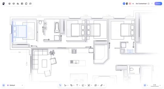
Rayon
Draw floor plans faster together Built for Speed, designed for Teams. Creativity Design beautiful and detailed architectural documents. Interoperability Use formats you know, export the files you need. DWG, DXF, PDF: you name it! Collaboration Gather your entire team in Rayon’s real-time multiplayer environment. Speed Work faster than ever using advanced edition tools, block libraries, and…
View On WordPress
1 note
·
View note
Text
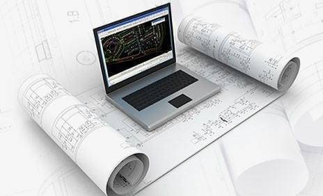
Architectural Cad Drawings: How to Create Neat and Accurate Floor Plans
Creating neat and accurate floor plans using Computer-Aided Design (CAD) software is a crucial skill for architects and designers. Here's a step-by-step guide to help you create professional and precise architectural CAD drawings for floor plans:

Select a CAD Software: Choose a CAD software that suits your needs. Popular options include AutoCAD, SketchUp, Revit, and ArchiCAD. AutoCAD is widely used in the industry and is known for its versatility.
Understand the Scale: Before you start drawing, determine the scale of your drawing. Decide how many feet or meters each unit on the drawing represents. This is crucial for accurate measurements and scaling of your floor plan.
Set Up Layers: Use layers to organize different components of your floor plan. For example, you might have separate layers for walls, doors, windows, furniture, and dimensions. This helps in better organization and control over the drawing elements.
Draw Walls: Begin by drawing the exterior walls of the building. Use the line or polyline tool to create straight or curved walls. Specify the dimensions and angles accurately. You can also use the offset tool to create interior walls based on the thickness of the walls.
Add Doors and Windows: Insert doors and windows into your walls. Ensure that they are placed accurately and to scale. Many CAD programs have libraries of standard door and window symbols that you can use.
Include Interior Elements: Draw in other interior elements such as stairs, columns, and built-in furniture. Pay attention to precise dimensions and positioning.
Insert Furniture and Fixtures: Add furniture and fixtures to your floor plan to give a sense of scale and functionality. Use standard symbols for furniture and fixtures, or create your own if needed.
Label Spaces and Rooms: Label each room or space within the floor plan. Include room names, dimensions, and any relevant notes. This makes it easier for others to understand the layout.
Add Dimensions: Include dimensions for all walls and relevant spaces. This helps in understanding the size and proportions of different areas. Most CAD software allows you to add dimensions easily.
Check for Accuracy: Regularly check your drawing for accuracy. Ensure that measurements are consistent, and elements align properly. Correct any errors as you go.
Use Snapping and Constraints: Take advantage of snapping and constraint features in your CAD software. These tools help you align and connect elements precisely, ensuring a clean and accurate drawing.
Save and Share: Save your work regularly and in different versions to avoid losing progress. When sharing your floor plans, consider exporting to common formats like PDF or DWG for compatibility with other software.
Remember, practice is key to becoming proficient in creating neat and accurate floor plans using CAD software. Explore the features of your chosen software and experiment with different tools to improve your skills.
1 note
·
View note
Text
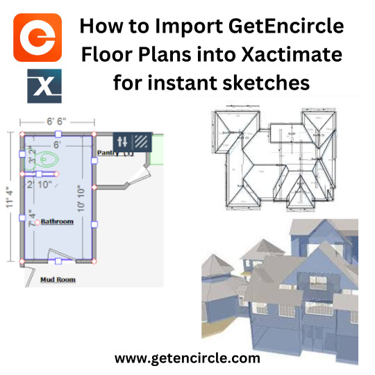
How to Import GetEncircle Floor Plans into Xactimate for instant sketches
Xactimate sketch integration is a feature in Getencircle Xactimate that allows users to create and import floor plan sketches directly into Xactimate. This can save time and improve accuracy, as it eliminates the need to manually create sketches or import them from other software programs. Xactimate is a widely used insurance software program for estimating property damage. To use the Xactimate sketch integration, users first need to create a sketch in a compatible software program, such as CAD or SketchUp. Once the sketch is complete, it can be exported to Xactimate in a variety of formats, including PDF,JPEG, PNG, and DWG. Once the sketch is imported into Xactimate, users can add annotations, measurements, and other information to it.
The Getencircle Xactimate sketch integration can be a valuable tool for insurance adjusters, contractors, and other professionals who need to create and manage floor plan sketches. It can save time and improve accuracy, and it can also help to ensure that all parties involved in an insurance claim have a clear understanding of the property damage.
There are many Benefits to using Xactimate Sketch Integration including:-1.Improves accuracy: Xactimate sketch integration ensures that sketches are accurate and up-to-date. This can help to prevent errors and omissions in insurance estimates. 2.Streamlines workflows: Getencircle Xactimate sketch integration streamlines the process of creating and managing sketches. This can help to improve efficiency and productivity.
3.Enhances communication: Xactimate sketch integration makes it easier to share sketches with other team members and stakeholders. This can help to improve communication and collaboration.
4.Reduces costs: Getencircle Xactimate sketch integration can help to reduce costs by eliminating the need for manual data entry and reducing the risk of errors and omissions. 5.Saves time: Xactimate sketch integration eliminates the need to manually create sketches or import them from other software programs. This can save a significant amount of time, especially for large or complex properties.
#Xactimate#Xactimate sketch#GetEncircle Xactimate#Xactimate sketch integration#Xactimate integration#sketch GetEncircle Xactimate
0 notes
Text
DWG FastView: Revolutionizing CAD Experience
DWG FastView: Revolutionizing CAD Experience DWG FastView is a cross-platform CAD software that meets designers’ demands in all kinds of situations. It is fully compatible with DWG, DXF, and offers various CAD features such as editing, viewing, measuring, dimensioning, and text finding. This software enables you to do real CAD work on the go and enjoy the best mobile CAD experience.To get more news about dwg fastview online, you can visit shine news official website.
Fast and Accurate Access to Your Drawings One of the highlights of DWG FastView is its ability to provide fast and accurate access to your drawings. It supports all DXF & DWG versions with no file-size limit. This feature allows you to create, view, and edit your drawings with easy-to-use advanced tools. Offline Drawings and No Registration DWG FastView stands out for its user-friendly approach. You can simply download DWG FastView and use it immediately with no registration needed. Even without the internet, you can save your masterpieces in the local workspace.
Sharing and Collaboration Sharing your design ideas has never been easier. With DWG FastView, you can share your drawings by link, group, email to team members. Drawings from E-mail, Cloud Service or Network Disk like Dropbox, OneDrive, Google Drive, Box or WebDAV can be opened, viewed, edited and shared as well with Internet.
Export to Various Formats DWG FastView supports exporting your .dwg file to PDF, JPEG, PNG, and BMP formats. This feature allows you to share your work freely with anyone.
Real CAD Work on Mobile With DWG FastView, you can do real CAD work on mobile. It provides advanced drawing and editing tools such as trim, offset, dimension and find text. You can also easily switch between 2D Visual mode and 3D Visual mode.
In conclusion, DWG FastView is a comprehensive software that revolutionizes the way we view and edit AutoCAD drawings. Whether you’re using a PC, mobile phone or web browser, DWG FastView provides a seamless CAD experience.
0 notes
Text
5 Of The Ideal Alternatives to AutoCAD
AutoCAD can be a flagship solution by Autodesk, the drafting market's juggernaut, designed to assist its customers with product or building design, manufacturing planning, structure and civil rights.
The sleek, three dimensional, computer-aided design software is fully-featured but prices far more than just other programs which fit its own capabilities. Because 1982, if it had been offered, AutoCAD's large selection of flexibility and features for use in several businesses ensure it is that the most goto product for most both students, professionals, and hobbyists alike.
But, Autodesk no-longer supplies endless licensing for CAD programs and converted into your centric certification instead, which forces people to seek out options. From the future it can be costlier to make the swap, although for CAD experts that aren't limited budget-wise, paying more than £ 1200 might appear worthwhile.
If you are the typical pupil or hobbyist doing work to get a budget, you really do not need to at all times choose AutoCAD. You can find a number of deserving contenders with very comparable encouraging infrastructure and also critical operation. The process is in selecting which AutoCAD options are worth your own time and effort, since the current marketplace is awash with gruesome knockoffs. Our five AutoCAD alternatives are not only inexpensive but see very related documents to all those AutoCAD reads, but easily integrate with AutoCAD alternative, and are instinctive to know.
5 of the Best HVAC CAD
SolidWorks
For a little while, CAD software has received pretty very great support for 3D modelling, however, its best strengths continue being as being a 2D-design and deploying architectural software. Solidworks, as its name suggests, can be actually a parametric solid modeller concentrated mainly around 3D designs. This usually means that you'll have to own any knowledge of engineering terms instead of just geometric ones.
youtube
The latest variant of SolidWorks has excellent features like the capability to do free hand sketches on touch screens. Despite being chiefly concentrated on 3D Growing, its 2 d sketching tool still remains functional, though it's much milder than that which you find in AutoCAD.
BricsCAD
This CAD system is popularly famous for its advantage capabilities and has several recognizable features for example native.dwg applications. If you should be familiar with AutoCAD's 2008 variant, BricsCAD has a marginally similar interface also loaded characteristics in second design and 3D direct modeling. You can utilize it with the significant systems such as macOS, Windows, and Linux, and countless of thirdparty apps from throughout the Earth, which are located on.dwg.
Being paid software like AutoCAD, BricsCAD is significantly more cheap using three editions: Classic, Pro, and Platinum. The latter is feature-packed with programs that aren't utilized in AutoCAD such as for example Sheet metal, 3D Evaluate, and BIM. BricsCAD additionally integrates with cloud, which includes a robust rendering engine, recognizes XREFS, and can be now also user friendly.
DraftSight
Draftsight can be an professional-grade alternative to AutoCAD, designed for people looking for improved means to browse, create, and share.dwg documents. The open 2nd CAD software isn't difficult to use and is dependant on advanced design including all of the tools which you should generate technical 2D drawings. From professional computer-aided design consumers to teachers and pupils, DraftSight is designed for a completely free download and activation in afew momemts. In addition, it runs on various OS platforms including Windows XP/Vista/7.
SketchUp (No Cost )
Previously Google SketchUp, this totally free tool can be a wonderful pick for CAD professionals. Sketch-up is actually just a 3D-modeling application employed in a wide array of applications from interior design; civil, architectural, and mechanical engineering; video game and film design. Available as a freeware variant, this tool works together several sorts of documents which include DWG, DXF, OBJ, XSI, and much a lot more, and may export HD animations along with PDFs.
LibreCAD (Free)
That is another free alternative program you can use that's feature-rich and commands a large following of customers and designers. LibreCAD is a high-tech opensource 2D-modeling software birthed from QCAD (later known as CADuntu) and looks AutoCAD in concept and also functions.
1 note
·
View note
Text
STL, IFC Files Processing Support & Rendering to Images or PDF Formats using Java
What’s new in this release?
Aspose team is pleased to announce the new release of Aspose.CAD for Java 17.9.0. This is primarily a maintaannce release whereby we have resovled certain issues incurring in API along with support for STL and IFC file formats. This release has improved the API rendering by introducing the support for STL and IFC file formats processing. Now, you can render these formats to images or PDF as per your requirements. For more about supported features, please visit documentation articles, Exporting STL To PNG Format and Exporting IFC Format To PNG. This release also includes important improvements and bug fixes, such as Missing text and blank area rendering issues when DWG is exported to PDF, Missing layers when saving DWG as JPEG, Resolution of DXF to PDF rendering issues, Incorrect image size for DWF, Difference between rendered PDF and Image, ImageException on exporting DWG to PDF, DXF to PDF conversion is producing very small shapes in resultant PDF, Converting DXF to PDF is generating incorrect PDF file (text missing and multiple pages), Support export option which automatically excludes empty layouts, Fix bug with shift of drawing on layouts, Converting DXF to PDF is not producing correct results: Incorrect color and orientation of text. The main new features added in this release are listed below
Support for IFC format
Implement support for STL format
When DXF is converted to PDF, output files has 3 pages instead of 1.
Converting DXF to PDF is splitting image on multiple pages in PDF
Incorrect image size for DWF
Difference between rendered PDF and Image
ImageException on exporting DWG to PDF
Text missing when DWG is exported to PDF
Layer not visible when saving dwg as jpg
DXF to PDF conversion is producing very small shapes in resultant PDF
Blank area when saving dwg as image and pdf
Converting DXF to PDF is generating incorrect PDF file (text missing and multiple pages)
Converting DWG to PDF format is producing incorrect PDF file of empty pages
Support export option which automatically excludes empty layouts
Fix bug with shift of drawing on layouts
Converting DXF to PDF is not producing correct results: Incorrect color and orientation of text
Newly added documentation pages and articles
Some new tips and articles have now been added into Aspose.CAD for Java documentation that may guide users briefly how to use Aspose.CAD for performing different tasks like the followings.
Exporting IFC Format To PNG
Exporting STL To PNG Format
Overview:Aspose.CAD for Java
Aspose.CAD for Java enables developers to convert AutoCAD DWG and DXF files to PDF, JPG, PNG, BMP, TIFF and GIF image formats. It is a native API and does not require AutoCAD or any other software to be installed. Developers can also convert the selected layers and layouts from the AutoCAD files. The conversion to PDF and Raster images is of very high quality. Developers can also remove entities from DWG and DXF documents. It also adds support for leader’s entity for DWG format.
More about Aspose.CAD for Java
Homepage of Aspose.CAD for Java
Download Aspose.CAD for Java
Online documentation Aspose.CAD for Java
#STL files rendering support#Export STL To PNG Format#IFC To PNG Export#saving DWG as JPEG#exporting DWG to PDF#DXF to PDF rendering#Java AutoCAD API#AutoCAD to raster image
0 notes
Text
7 Reasons Why You Should Use Revit Architecture Software
Revit is versatile software that facilitates better workflows, streamlines modelling, and promotes team collaboration for architects and designers through the use of advanced tools and important features. Numerous fields depend on this standard, as it is the only reliable source for productive workflows and reliable results in the field. Innovative software allows for individualised structure designs, rapid modification, and superior depiction. Find out more about the interconnectivity features that promote teamwork among specialists.

The price tag may change due to the inclusion of Revit in the planning phase. The entire cost of a project will be impacted by how long it takes to create a design that is ready for implementation. Managers of high-stakes initiatives need to devise strategies for lowering the probability of expensive mistakes. Anyone involved in the fields of design, architecture, engineering, building, and allied fields will find this information useful.
It's useful in a wide variety of fields since it improves design accuracy. With the advent of Revit software, previously relied-upon drawing for architectural modelling and documentation became obsolete. As a result of using this product, experts can take advantage of Revit software's design planning and construction accuracy.
Most importantly, the building's structure and floor plans need to be altered regularly during the design phase. Revit BIM software streamlines the processes of designing and drawing buildings.
Plans, sections, and elevations, along with every other part of a building, are intricately interwoven in a Revit architecture model. The programme updates all dependent parts of the model if any changes are made to the model, therefore affecting the entire building model.
Vast Library of Parametric Building Components
Revit comes with a full collection of parametric building design components. It also allows rapid adjustments to the current components. Parametric objects that have been modified or created from scratch are saved in this library for later use. Stored parametric building objects can be a great resource for an architect when working on a new project and has to show off their work to potential clients.
Coordination
Whether you're an architect coordinating models as part of the design process or a builder conducting constructability assessments, Revit's many capabilities for coordinating between models, file formats, disciplines, and trades will come in handy. Revit provides tools for keeping tabs on linked models, reviewing notifications about changes made to them, incorporating model elements from linked models into a user's base model, and alerting other teams working on the same project of any issues that require fixing. If you’re looking for Revit Courses in Nagpur, CADD has got you covered.
Analysis of Energy Use
Revit includes a number of analytical tools for determining how your building design affects the environment, which is very useful given the importance of sustainable architecture in today's design and construction processes. Using the 'Energy Optimization' tools native to Revit (and available plug-ins), in tandem with 'Insight 360' in the cloud, architects and engineers can foresee the potential consequences of their designs at any stage of the process, without having to start over with a fresh model or switch to a different programme.
Extreme flexibility
In contrast to AutoCAD, Revit keeps all project information in one central file. It enables a team to collaborate on a single file and have their modifications automatically merged when they are saved. In addition to DWG, DXF, DGN, PDF, and JPEG, Revit can also import and export. Are you looking for Best Institute for AutoCAD Training in Nagpur. Join CADD Centre Nagpur - Best Institute for CADD Courses.
Accessible Via the Cloud
In many businesses nowadays, working from home is essential. One of the advantages of storing Revit files on the cloud is that they may be accessed from any device, at any time. Revit is compatible with a wide variety of cloud-based software environments. However, Autodesk's BIM 360 platform stands out as the clear frontrunner; it serves as a "server in the cloud" where users can store their models, push changes to those models, annotate models and sheets, communicate with team members, and even assist with facility management after construction completion handoff, all from within a web browser. By linking to the cloud, Revit's strength and collaborative features are amplified.
Parametric Modeling
Parametric modelling is an umbrella term for any technique that generates a 3D model according to predefined parameters. Revit employs families, a parametric modelling tool, to achieve this. Title blocks, 3D views, and structural elements like walls and floors are all part of a larger "family" in Revit, some of which are pre-installed, some may be accessed via libraries, and still others can be created from scratch. Using Revit, a user can construct a family by giving dimensions and properties to 2D or 3D data, which can subsequently be altered using the program's editing tools . By doing so, Revit models gain more authority in the construction process.
Whether you’re an architect or a budding student, AutoCAD Architecture Training Courses can help you jump start your career and will help you get all the guidance from the industry experts about the software.
For any queries or details Feel free to call us on- Nandanvan- 7507111164 I Sadar-7507111145, Or Visit our website- www.caddcentrenag.in/
#mechanical cad courses#revit courses in nagpur#architectural cad courses in nagpur#solid works courses in nagpur#cadd centre nagpur
0 notes
Text
AutoCAD vs SolidWorks: Which is Best?

We'll explore a comparison between AutoCAD and SolidWorks in this article. While SolidWorks is a three-dimensional (3d) modeling mechanical designing software that is only compatible with the operating system Microsoft Windows, AutoCAD is a computer-aided two-dimensional (2d) and three-dimensional (3d) designing and drafting software that is compatible with both Microsoft Windows and macOS. Both of them can be used for engineering design, building projects, and graphics creation. Engineers and professionals from various trades utilize these two programs for a variety of professional tasks. You can easily distinguish SolidWorks software from AutoCAD software in this post. To better comprehend AutoCAD software and SolidWorks software, we shall talk about all elements of these two programs.
The 3D modeling community of today has access to a vast range of 3D modeling software, with updates released yearly and new and improved forms of software for each purpose imaginable. However, the top manufacturers of 3D modeling software, namely Dassault Systems and Autodesk, continue to hold the majority of the market share. We compare SolidWorks, and AutoCAD in depth. This information should aid you in making the best CAD software selection possible.
Comparison Between AutoCAD and SolidWorks Software
Many design professionals are very familiar with AutoCAD software, and engineering students are also very familiar with it. These students begin their learning of design with AutoCAD software, but SolidWorks enters the learner's knowledge when they start to lean toward learning three-dimensional (3d) modeling. Therefore, the fundamental requirements for using any piece of software vary. Both pieces of software are used for academic and professional endeavors.
What is AutoCAD?
As was already noted, the CAD program AutoCAD is intended for use by interior designers, architects, and engineers. Instead of the former way of making technical drawings by hand-drafting them, it is now usual practice in the industry to use a computerized tool to create a digital version of your design.
Users using AutoCAD can produce a wide variety of 2D and 3D designs and drawings. Using some basic capabilities like copy and paste, form, position, and size, these drawings may be created and modified much more quickly and easily. It has a wide range of applications in numerous industries, including greeting cards, fine art, architecture, and design.
What is SolidWorks?
One of the most widely used CAD applications by professionals worldwide is SolidWorks. It has an astonishing selection of capabilities that enable users to construct any shape imaginable. It has a reputation for being relatively simple to use and straightforward to learn, making it a 3D CAD tool that is approachable for users of all ability levels.
Simulation, motion, assembly, ScanTo3D, and photo rendering are just a few of its numerous functions. What is the purpose of SolidWorks? SolidWorks can be utilized in a wide range of industries, including but not limited to those in the automotive, electronics, medical, defense, and transportation sectors.
AutoCAD Features
3D Modeling and Visualization
AutoCAD Mobile App
Command Line
Data Extraction
Data Linking
DWG and Image References
Dynamic Blocks
Geographic Location and Online Maps
Import 3D Models
Multifunctional Grips
Parametric Constraints
PDF and DGN Import/Export/Underlay
Photo Studio
Revision Clouds
Sheet Set Manager
Solid, Surface, and Mesh Modeling
SolidWorks features
3D Solid Modeling
Advanced Surface Design
Advanced Surface Flattening
Automatic Drawing View Creation and Update
Bill of Materials (BOM)
CAD Dimensioning, Tolerancing, and Annotations
CAD Import/Export
CAD Productivity Tools – SOLIDWORKS Utilities
CAD Search
CAD Standards Checking (Design Checker) and Drawing Comparison
Conceptual Design
Conceptual Design
Large Assembly Design
Mold Design
Piping and Tubing Design
Plastic and Cast Part Design Direct Model Editing
Which Industry?
With the introduction of toolkits like AutoCAD Mechanical, AutoCAD Architecture, and AutoCAD Electrical throughout the years, as well as the inclusion of AutoCAD 3D modeling capabilities, AutoCAD has evolved from its original purpose as software for 2D architectural and construction design.
On the other hand, SolidWorks was initially intended to be a tool for 3D product modeling, mechanical part design, and simulation. It didn't begin to delve into the world of architecture and other engineering features until much later.
AutoCAD Software
Architectural and construction design
Civil and structural engineering
SolidWorks Software
Electronic, electrical, and technology design
Mechanical parts and assembly design
Automotive and aerospace design
Final Thoughts
You may now more clearly comprehend the key distinctions between SolidWorks CAD software and AutoCAD software after carefully reading this article from beginning to end, and you can make excellent use of them in your designing or modeling projects. After reading this post, picking one of them will be a lot simpler for you, and this software will provide you a growing number of advantages.
0 notes
Text
DWG FastView: A Comprehensive Solution for Viewing and Editing CAD Drawings
DWG FastView: A Comprehensive Solution for Viewing and Editing CAD Drawings In the world of Computer-Aided Design (CAD), the ability to view and edit drawings efficiently is crucial. One tool that has emerged as a comprehensive solution for this need is DWG FastView.To get more news about dwg fastview, you can visit shine news official website.
DWG FastView is a free online DWG viewer and editor. It allows users to open CAD drawings in all major browsers without the need for installation or upgrades1. This cross-platform application is available for web, mobile, and Windows, making it accessible from virtually anywhere. One of the key features of DWG FastView is its fast drawing open capability. This feature allows users to quickly load their CAD drawings, making it an efficient tool for those who need to work with complex designs. Additionally, DWG FastView is easy to use, making it a cost-effective solution for both professionals and beginners.
DWG FastView also offers a range of features that enhance the viewing experience. With an embedded tangent entity interpreter, it can display tangent high version drawings perfectly. It also supports different versions of DWG files and provides all-round features of layer and layout, making the view of drawings effective.
Another notable feature of DWG FastView is its support for cloud storage1. Users can access their project files stored in the cloud from their browser, mobile, and computer anytime, anywhere. This feature not only enhances accessibility but also facilitates collaboration. Users can share or exchange their drawings conveniently and safely.
In addition to viewing capabilities, DWG FastView also offers editing features. Users can export their .dwg file to PDF, JPEG, PNG, and BMP formats. It also includes a measure tool for measuring length and area, meeting the basic needs of most users.
For mobile users, DWG FastView offers the ability to view, edit, and annotate CAD drawings on mobile devices. This feature allows users to share their design ideas anytime and anywhere.
In conclusion, DWG FastView is a comprehensive software solution for viewing and editing Autocad drawings in PC, mobile phone, and web browsers. With its range of features and cross-platform accessibility, it serves as an efficient and versatile tool for anyone working with CAD designs.
0 notes
Text
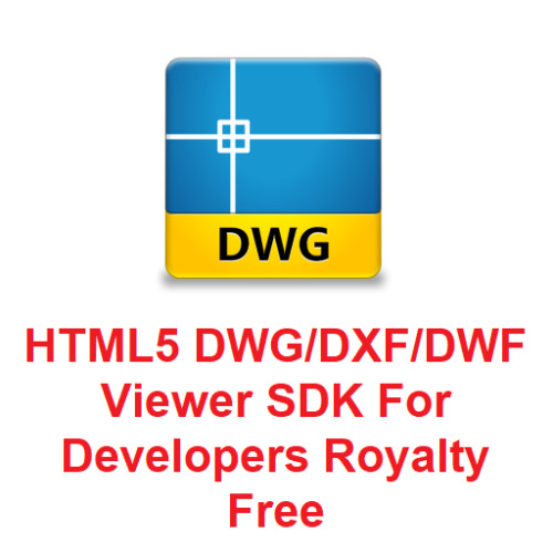
VeryUtils HTML5 DWG Viewer SDK for Developers Royalty Free
VeryUtils HTML5 DWG Viewer SDK is a Royalty Free Web CAD SDK for developers. HTML5 DWG Viewer SDK is a HTML5 component for viewing DWG and other CAD files on the Internet, Intranet, SharePoint, Office 365 and other online HTML5 enabled technologies. HTML5 DWG Viewer SDK doesn't require AutoCAD installation or any other third party applications or components. HTML5 DWG Viewer SDK package is provided with C++, VC++, C#, VB, VB.NET, HTML, PHP, Python, Java, etc. demo examples.
https://veryutils.com/html5-dwg-viewer-sdk
You can embed a DWG Viewer into your own software to add the features of viewing and printing DWG, DXF and DWF files. HTML5 DWG Viewer SDK is a standalone product, you can integrate it into both online and offline applications, for example, you can call it from a Windows Desktop Application or a Web Service.
Our CAD Viewer SDK is a fast, accurate and reliable CAD viewing component for any application. Our CAD Viewer SDK is proven to handle the large and complex drawings used in architectural, engineering and construction workflows.
HTML5 DWG Viewer SDK includes a copy of DWG to PDF Converter Command Line plus a HTML5 Frontend Viewer application.
Please notice: HTML5 DWG Viewer SDK runs only on Windows Servers, but it is accessible from all platforms from web browsers.
HTML5 DWG Viewer SDK Highlight Features: * View DWG, DXF and DWF in versions from R2.5 to 2022. * Able to load CAD drawings from both local disks and network websites. * Able to view CAD drawings (DWG, DXF, DWF files) with zoom and rotate operations. * Completely standalone utility, don't require any products from AutoDesk. * Support print functions for DWG, DXF, DWF files. * Manage all of your CAD drawings without AutoCAD. * Quick visualization of 2D and 3D CAD files in a browser or SharePoint. * Layer management and different display modes. * Merging of two or more files. * Export to PDF format. * Export to DXF format. (Available in custom-build version) * Copying of the drawing display area to the clipboard. * Text search. * Printing with a customized stamp. * Editing drawing data programmatically. * Works independently of AutoCAD. * Support C++, VC++, C#, VB, VB.NET, Delphi, HTML, Python, PHP, etc. program languages.
Supported Basic Formats: * CAD formats: AutoCAD DWG (up to Autodesk AutoCAD 2023), DXF, DWF. * Vector formats: PDF.
Supported Extended Formats (Available in custom-build version): * CAD formats: DWT, HPGL, GBR, PLT. * Vector formats: SVG, CGM, EMF, WMF. * 3D formats: STEP, STP, IGES, IGS, SLDPRT, X_T, X_B, BREP, STL, SAT (ACIS®), OBJ, 3DS. * Raster formats: PNG, BMP, JPG, GIF, TIFF, TGA.
View CAD Files on Any Platform HTML5 DWG Viewer SDK allows you to view complex CAD (DWG, DXF, DWF) and 20+ other file types quickly and flawlessly, even at high zoom, on all platforms and devices.
No CAD Licenses Support various CAD formats, including DWG, DXF, DWF, without you or your users needing any CAD software, CAD licenses, or third-party dependencies.
Fully Customizable UI/UX HTML5 DWG Viewer SDK's UI/UX is written in HTML5 source code, so you can show or hide any buttons on toolbar easily. You can also hide unnecessary features or add custom features.
Print Function Generate high-quality vector printouts. Rasterize specific regions, subsets, or layers of a drawing. You can combine more DWG, DXF, DWF files into a PDF portfolio for easier and faster printing at scale.
Web, Server, Desktop Add CAD Viewing functionality to any platform with a unified API across web, Windows, Mac, or Linux. Use a single codebase with Xamarin, React Native, Flutter, or other frameworks. Please notice: HTML5 DWG Viewer SDK runs only on Windows Servers, but it is accessible from all platforms.
Web-based CAD Viewer application for DWG, DXF, DWF formats The API is based on HTML5 and gives an unlimited number of clients opportunity to run the application from anywhere.
Supported Web Browsers: Internet Explorer, Chrome, Firefox, Opera and other both desktop and mobile versions that support HTML 5.
Scope of Use: Databases, monitoring and remote control programs, document management systems and many others.
What kind of systems can integrate this SDK? * Enterprise network disk * Office automation system * Collaborative design system * Enterprise Resource Planning system * File management system * Archives management system * Project management system * Corporate website * Browser or HTML programs * Mobile applications
Support and Development: HTML5 DWG Viewer SDK is provided with free technical support and updates within the major version. If you have any questions, please feel free to contact us via email, phone, Skype or online chat. Our experts will get back to you as soon as possible.
We are always ready to extend the library functionality to suit your requirements or build a custom solution based on HTML5 DWG Viewer SDK (Web CAD SDK). If you are interested, please feel free to contact us.
See Also:
DWG to Any Converter Command Line https://veryutils.com/dwg-to-any-converter-command-line
DWG to PDF Converter Command Line https://veryutils.com/dwg-to-pdf-converter-command-line
DWG to Image Converter Command Line https://veryutils.com/dwg-to-image-converter-command-line
PDF to DWG Converter Command Line https://veryutils.com/pdf-to-dwg-converter-command-line
DWG to SVG Converter Command Line https://veryutils.com/dwg-to-svg-converter-command-line
Raster to Vector Converter Command Line https://veryutils.com/raster-to-vector-converter-command-line
DWG to Vector Converter Command Line https://veryutils.com/dwg-to-vector-pdf-converter-command-line
DWG and DXF Converter SDK for Developers Royalty Free https://veryutils.com/dwg-and-dxf-converter-sdk
0 notes