#AutoCAD to raster image
Explore tagged Tumblr posts
Visit Tumblr Blog
Explore Tumblr blogs with no restrictions, modern design and the best experience.
Last Seen Tumblr Blogs


Fun Fact
There were a total of 171.5 billion posts on Tumblr in 2019.
Text
Top Tools for Creating High-Impact 3D Map Illustrations in Architecture

Mastering the Landscape: Top Tools for Creating High-Impact 3D Map Illustrations in Architecture
In the dynamic world of architecture and urban planning, communication is key. Whether you're pitching a master plan, showcasing a new development, or explaining complex infrastructure, conveying spatial relationships and contextual nuances is paramount. While traditional 2D maps provide basic information, they often fall short in capturing the imagination or truly illustrating the depth and impact of a project within its environment. This is where high-impact 3D Map Illustration steps in, transforming flat data into compelling, easily digestible, and aesthetically rich visual narratives.
This blog will explore the leading software and workflows that empower designers to create high-impact 3D Map Illustration for architectural projects, ensuring their visions are understood and embraced.
The Power of 3D Map Illustration in Architectural Communication
Before diving into the tools, it's essential to understand why 3D Map Illustration is so vital in architecture:
Holistic Understanding:
It provides a bird's-eye view of a project within its entire context, including existing buildings, topography, and proposed developments. This is crucial for large-scale urban planning projects or complex architectural complexes.
Enhanced Clarity:
Complex spatial relationships, pedestrian flows, and vehicular routes become immediately apparent, simplifying otherwise intricate data.
Stakeholder Engagement:
Visuals are universally understood. A powerful 3D Map Illustration can bridge the gap between technical details and public understanding, fostering buy-in from diverse audiences, including investors, city officials, and local communities.
Design Validation:
Architects can use these maps to test and refine their designs in a real-world context, identifying potential issues or opportunities before construction.
Foundation of Precision: 3D Vector Maps Software
The bedrock of any high-impact 3D Map Illustration is accurate, scalable geographic data, best handled by software that generates 3D Vector Maps. Unlike raster images, vector data can be scaled infinitely without losing quality, making it ideal for maps that need to be viewed at various zoom levels.
Here are the top tools for creating and working with 3D Vector Maps:
GIS Software (e.g., ArcGIS Pro, QGIS):
Geographic Information Systems are the gold standard for handling spatial data. They allow architects to import real-world topographical data (like LiDAR point clouds or DEMs), aerial imagery, and existing building footprints. GIS software can then process this data to create accurate 2D and 3D base maps. While not directly creating the artistic render, they provide the precise foundation of the 3D Vector Maps from which the illustration will emerge. QGIS is a powerful open-source alternative, making professional-grade 3D Vector Maps accessible.
CAD Software (e.g., AutoCAD, MicroStation):
These can be used to generate precise 2D and 3D building outlines, roads, and landscape elements, which can then be imported into more specialized 3D modeling environments. While primarily used for technical drawings, their precision is vital for the accuracy of 3D Vector Maps in an architectural context.
Vector Graphics Software (e.g., Adobe Illustrator, Affinity Designer):
While not inherently 3D, these tools are invaluable for refining the 2D elements that often form part of 3D Vector Maps. They can be used to create clean lines, labels, icons, and legends that enhance the clarity and aesthetic appeal of the final 3D Map Illustration.
Sculpting the Vision: Architecture Illustration Tools
Once the precise 3D Vector Maps are established, the next step involves bringing the architectural elements to life with artistic flair and realism. This is where dedicated 3D modeling and rendering software, often used for Architecture Illustration, plays a crucial role.
Here are the leading tools for crafting detailed Architecture Illustration:
Autodesk Revit / ArchiCAD (BIM Software):
Building Information Modeling (BIM) software is increasingly becoming the starting point for architectural projects. Revit and ArchiCAD allow architects to create intelligent 3D models of their buildings, complete with material information and structural data. These models can then be directly exported or linked to rendering engines to create the core of the Architecture Illustration. Their ability to manage complex building data makes them ideal for ensuring accuracy in the Architecture Illustration embedded within the 3D Map Illustration.
Trimble SketchUp:
Known for its user-friendliness and intuitive interface, SketchUp is excellent for quick 3D massing studies, conceptual design, and creating detailed architectural components. While it may require plugins for advanced rendering, its ease of use makes it a popular choice for rapidly prototyping the architectural elements that will populate the 3D Map Illustration.
Blender:
This Cycles and Eevee render engines can produce stunning photorealistic results, making it a highly versatile tool for creating every aspect of a detailed Architecture Illustration. The active community and constant development make Blender an increasingly popular choice for professional Architecture Illustration.
Autodesk 3ds Max / Maya:
These are industry-standard 3D software packages renowned for their advanced modeling, animation, and rendering capabilities. They offer unparalleled control over scene setup, lighting, and material creation, making them ideal for producing the highest quality photorealistic Architecture Illustration for complex projects and large-scale 3D Map Illustration. Their extensive feature sets allow for meticulous detail and artistic expression.
Bringing it All Together: Rendering and Compositing for High-Impact 3D Map Illustration
The final step in creating a high-impact 3D Map Illustration involves bringing together the precise 3D Vector Maps and the detailed Architecture Illustration elements, then rendering them with compelling lighting and post-production effects.
Key rendering and compositing tools include:
V-Ray / Corona Renderer
These are highly regarded photorealistic rendering engines that integrate with various 3D modeling software. They offer advanced lighting, material, and camera controls, allowing artists to achieve stunning realism, depth, and atmosphere in their 3D Map Illustration.
Twinmotion / Lumion (Real-time Renderers):
These tools are gaining immense popularity due to their speed and ease of use. While perhaps not reaching the absolute pinnacle of photorealism as offline renderers, they produce excellent results quickly and are fantastic for iterating on the overall look and feel of the 3D Map Illustration or creating short animations.
Adobe Photoshop / Affinity Photo (Image Editing/Compositing):
After rendering, post-production is crucial for refining the final 3D Map Illustration. These image editing software packages allow artists to adjust colors, contrast, add atmospheric effects (like fog or haze), integrate labels, legends, and other graphic elements, and even subtly enhance certain details to make the Architecture Illustration truly pop within the overall map.
Conclusion
Creating high-impact 3D Map Illustration in architecture is a multidisciplinary art form that blends technical precision with artistic vision. By leveraging the power of software that generates accurate 3D Vector Maps, sculpts detailed Architecture Illustration, and refines the final image through advanced rendering and compositing, architects and visualization transform urban plans into easy-to-understand visual narratives.
0 notes
Text
Professional CAD Conversion Services to Transform Your Legacy Data

At Shalin Designs, we specialize in high-quality CAD conversion services tailored to modernize your outdated or paper-based engineering drawings. Whether you’re a manufacturer, architect, contractor, or designer, our expert team converts your hand-drawn sketches, blueprints, or scanned images into precise, editable CAD files — giving you more control, better accuracy, and improved productivity.
Why CAD Conversion Matters for Your Business
Many companies still rely on legacy data stored as paper drawings or raster images. These formats can be hard to manage, edit, or replicate. With CAD conversion, you can:
Digitize old designs for long-term storage
Update and reuse legacy files with modern CAD software
Eliminate risks of data loss or damage
Improve collaboration with editable, standardized formats
Our goal is to help you bridge the gap between old and new technologies while ensuring accuracy, compliance, and efficiency in your design workflows.
Our CAD Conversion Services
We offer a full suite of CAD conversion services for multiple industries. No matter the size or complexity of your project, Shalin Designs delivers quick, precise, and cost-effective results.
1. Paper to CAD Conversion (P2C)
Convert hand-drawn paper sketches, schematics, or blueprints into editable CAD files (DWG, DXF, etc.). Ideal for architects, civil engineers, and construction professionals.
2. PDF to CAD Conversion
We extract vector-based data from PDFs and convert it into 100% accurate CAD drawings. Our drafters ensure correct scaling, layers, dimensioning, and technical accuracy.
3. Image to CAD Conversion (Raster to Vector)
Turn raster images (JPG, PNG, TIFF) into editable vector files. We use manual redrawing to avoid common issues with auto-tracing and maintain high precision.
4. 2D to 3D CAD Conversion
Looking to upgrade your 2D drawings into 3D models? We can transform flat layouts into detailed 3D CAD models for simulation, rendering, or production.
5. Legacy CAD File Conversion
Have files in outdated formats like MicroStation, IGES, or Solid Edge? We convert them into your preferred modern CAD formats, including AutoCAD, SolidWorks, Revit, and Inventor.
Get Started with Shalin Designs Today
Looking to upgrade your old drawings or need CAD conversions for your next project? Shalin Designs is your trusted partner. We’ve helped clients across the USA and globally modernize their design files for easier collaboration and increased productivity.
👉 Get a free quote now or contact us to discuss your CAD conversion needs.
#cad conversion services USA#paper to cad conversion#pdf to cad drafting services#raster to vector cad conversion#image to cad conversion#2D to 3D cad conversion#architectural cad conversion#mechanical cad conversion#cad digitization services
0 notes
Text
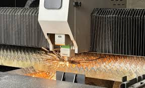
The Essential Guide to Laser Cutting File Formats
YOU CAN ALSO TRY THIS PRODUCT:300.000 Laser Cut Files

Introduction
Brief overview of laser cutting technology
Importance of vector files in precision cutting and engraving
Understanding Vector Files
Difference between raster and vector graphics
Why vector files are essential for laser cutting
Popular Vector Formats for Laser Cutting
Overview of commonly used file formats: SVG, DXF, AI, CDR, and EPS
SVG (Scalable Vector Graphics)
Key features and advantages
Common use cases in laser cutting
DXF (Drawing Exchange Format)
Origin and compatibility
Why DXF is favored for CAD and industrial applications
AI (Adobe Illustrator File)
Role of AI files in professional design workflows
Advantages of using AI for intricate laser cutting designs
CDR (CorelDRAW File)
Popularity among designers and engravers
How CDR files integrate with laser cutting machines
EPS (Encapsulated PostScript)
Versatility in design and printing
Strengths and limitations for laser cutting
Choosing the Right File Format for Your Project
Factors to consider: material type, machine compatibility, and design complexity
Preparing Files for Laser Cutting
Key steps to optimize vector files
Common mistakes and how to avoid them
Conclusion
Summary of key takeaways
Encouragement to experiment with different file formats
Now, here’s the complete article:
The Essential Guide to Laser Cutting File Formats
Introduction
Laser cutting has revolutionized the way creators, hobbyists, and industrial professionals bring designs to life. Whether crafting intricate patterns on wood, engraving logos on acrylic, or slicing precise metal components, the success of a project hinges on the quality of the digital file used. Vector files, such as SVG, DXF, AI, CDR, and EPS, are the backbone of laser cutting, enabling precise, scalable, and adaptable designs. Understanding their differences and applications ensures seamless results in any laser-cutting endeavor.
Understanding Vector Files
Digital graphics are broadly classified into two types: raster and vector graphics. Raster images, such as JPEGs and PNGs, are composed of pixels, which lose quality when resized. In contrast, vector files use mathematical equations to define shapes, lines, and curves, making them infinitely scalable without distortion. This characteristic is vital for laser cutting, as precision and clarity are paramount.
YOU CAN ALSO TRY THIS PRODUCT:300.000 Laser Cut Files
Popular Vector Formats for Laser Cutting
Laser cutters are compatible with a range of vector formats, each offering unique benefits. Among the most widely used are:
SVG (Scalable Vector Graphics) – A web-friendly, open-standard format
DXF (Drawing Exchange Format) – Designed for CAD and technical applications
AI (Adobe Illustrator File) – Industry standard for detailed graphic design
CDR (CorelDRAW File) – Favored by designers using CorelDRAW software
EPS (Encapsulated PostScript) – A versatile format with broad software compatibility
Each format serves a specific purpose, and selecting the right one depends on the project’s requirements.
SVG (Scalable Vector Graphics)
SVG files are lightweight, adaptable, and widely supported. They use XML-based code to define vector shapes, making them easy to modify using design software like Adobe Illustrator, Inkscape, and CorelDRAW.
Why SVG for laser cutting?
Maintains crisp quality at any size
Supports transparent backgrounds
Easily editable for quick modifications
Many online marketplaces provide free and premium SVG files for laser cutting, making it a go-to format for small businesses and DIY enthusiasts.
DXF (Drawing Exchange Format)
Originally developed by Autodesk for AutoCAD, DXF files have become a standard in industrial and engineering applications. Unlike other formats, DXF files are purely vector-based, ensuring they are highly precise and compatible with CAD software.
Key advantages of DXF:
Ideal for CNC machining and technical drawings
Preserves exact dimensions, essential for manufacturing
Compatible with almost all laser-cutting software
For architectural models, mechanical components, and custom signage, DXF is often the preferred choice.
AI (Adobe Illustrator File)
The AI file format is a proprietary format of Adobe Illustrator, widely regarded as the gold standard in graphic design. It allows designers to create complex, multi-layered artwork with extreme precision.
Why AI files stand out:
Supports advanced design tools and effects
Retains original layers and paths for detailed editing
Works seamlessly with Adobe Creative Suite
However, not all laser-cutting software directly supports AI files, so they may need to be exported as SVG, DXF, or EPS before use.
CDR (CorelDRAW File)
CorelDRAW is a popular choice among engravers and sign-makers, and its native CDR format is optimized for vector-based design workflows. Many commercial laser engraving businesses rely on CorelDRAW due to its robust node-editing capabilities and precision control.
Advantages of CDR files:
Ideal for text-heavy and logo-based designs
Advanced shape manipulation tools
Directly compatible with certain laser cutter software
However, CDR files may require conversion for non-CorelDRAW users.
EPS (Encapsulated PostScript)
EPS is a versatile format commonly used in printing and design. It supports both vector and raster data, making it useful for high-resolution engraving projects.
Strengths of EPS files:
Can store detailed vector graphics with embedded fonts
Supported by most professional design applications
Suitable for large-format laser engraving
One drawback is that EPS files can be bulky compared to SVG or DXF. They also sometimes require specialized software for full editing capabilities.
Choosing the Right File Format for Your Project
Selecting the best file format depends on multiple factors, including:
Material type: Some files work better for intricate cuts on delicate materials, while others suit robust applications.
Software compatibility: Ensure your laser cutter supports the chosen file format.
Design complexity: Detailed engravings may require AI or EPS, while simple cuts may work best with SVG or DXF.
Preparing Files for Laser Cutting
Before sending a file to a laser cutter, it must be optimized for accuracy and efficiency. Here are some best practices:
Convert text to outlines – Prevents font issues during processing
Ensure proper line thickness – Thin lines may not be detected by the laser
Use RGB color mode – Some laser cutters use colors to differentiate cutting and engraving operations
Check for overlapping paths – Avoids duplicate cuts that can damage materials
Proper preparation ensures cleaner cuts, minimal material waste, and faster production times.
YOU CAN ALSO TRY THIS PRODUCT:300.000 Laser Cut Files
Conclusion
Mastering laser-cutting file formats empowers creators to bring their ideas to life with precision and efficiency. Whether you’re an artisan crafting intricate wooden ornaments, an engineer designing machine components, or a hobbyist experimenting with acrylic etching, understanding SVG, DXF, AI, CDR, and EPS will help streamline the design process. By selecting the right format and optimizing files correctly, anyone can achieve professional-grade laser-cut results.
YOU CAN ALSO TRY THIS PRODUCT:300.000 Laser Cut Files
0 notes
Text
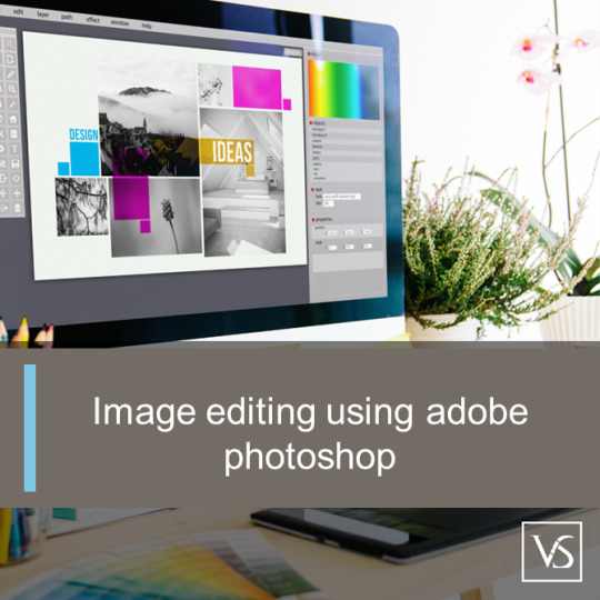
Mastering Image Design in Adobe Photoshop: Essential Tools and Techniques
Image editing using adobe photoshop : Top Questions Answered
1.How to design a picture in adobe Photoshop?
To design a picture in Adobe Photoshop, start by creating a new document. Use the toolbar for tools like Brush, Shape, or Text tool. Import images or use layers to build your design. Adjust colors, apply effects, and use filters as needed. Save your work in the desired format when finished. Experiment to enhance your skills.
2. What is the difference between adobe Photoshop and AutoCAD?
Adobe Photoshop is a graphic design software primarily used for editing and creating images, focusing on raster graphics. AutoCAD, on the other hand, is a computer-aided design (CAD) software used for creating precise 2D and 3D drawings, mostly in engineering and architecture. Each serves different purposes within their respective fields.
3. What are the 10-layer styles in adobe Photoshop?
The 10-layer styles in Adobe Photoshop are:
1. Drop Shadow
2. Inner Shadow
3. Outer Glow
4. Inner Glow
5. Bevel and Emboss
6. Satin
7. Colour Overlay
8. Gradient Overlay
9. Pattern Overlay
10. Stroke
These styles enhance layers with various effects for creative designs.
4. How many formats are there in adobe Photoshop?
Adobe Photoshop supports numerous file formats for saving and exporting images. The primary formats include PSD (Photoshop Document), PSB (Photoshop Big), JPEG, PNG, GIF, TIFF, and BMP, among others. Each format serves different purposes, such as preserving layers or optimizing for web use. Overall, there are dozens of formats available in Adobe Photoshop.
5. What is the full size of Adobe Photoshop?
The full size of Adobe Photoshop varies depending on the version and platform. Typically, the installation file is around 1.5 to 2 GB, but the total disk space required can be around 4 GB or more after installation. Keep in mind that additional space may be needed for plugins, brushes, and other resources. Always check Adobe's official site for specifics.
Visit: VS Website See: VS Portfolio
0 notes
Text
VeryUtils DWG to PDF Converter SDK for Developers Royalty Free
VeryUtils DWG to PDF Converter SDK for Developers Royalty Free.
https://veryutils.com/dwg-to-pdf-converter-sdk
VeryUtils AutoCAD DWG to PDF Converter SDK is a DWG, DXF and DWF to PDF Conversion DLL Library for Developers. You can use it to convert DWG to PDF, DXF to PDF and DWF to PDF directly without the need for AutoCAD. This software swiftly and effortlessly converts DWG, DXF and DWF files into high-quality PDF files. VeryUtils DWG to PDF Converter SDK is a SDK that you can integrate it into your software for redistribution after purchasing the royalty-free license.
VeryUtils DWG to PDF Converter SDK provides you with flexibility and robust functionality to convert DWG, DXF and DWG files to PDF files on the fly. It's the best SDK software for converting AutoCAD files to PDF files on server and client systems. AutoCAD VeryUtils DWG to PDF Converter SDK is a control component that allows you to convert DWG to PDF, DXF to PDF, and DWF to PDF directly, without requiring AutoCAD.
✅ VeryUtils DWG to PDF Converter SDK Key Features:
Convert thousands of files while maintaining folder structure.
Batch combine multiple DWG files into a single PDF (requires PDF Split-Merge Software).
Create a .bat file to reuse conversion settings.
Send prompts directly within the SDK environment.
Stand-alone software; AutoCAD is NOT required.
Supports all versions of AutoCAD DWG, DXF, DWF files.
PDF encryption and password protection.
Supports SDK operation; you can call it from a script or your application.
Batch conversion supported; you can call it from a .bat file.
Supports all Windows systems, including both 32-bit and 64-bit systems.
Convert all DWG and DXF files to PDF files in a folder and its sub-folders recursively with one SDK.
Support for all versions of DWG, DXF and DWF formats.
Set page size directly or choose predefined sizes quickly.
Support for AutoCAD pen sets file (*.ctb).
Automatically adjust output paper size with layout settings.
Export layer and raster image objects to PDF.
Support for 3D objects hidden line removal.
Support for searchable text entities and hyperlinks.
Export arc/circle objects to true arc/circle objects in PDF.
Support for pen width and destination colors settings; settings can be exported/imported.
Convert model space, all layouts, all paper space, or the last active layout to PDF.
Export to compressed PDF file format.
Automatically create bookmarks with layout and file names.
Adjust PDF file quality with DPI parameter.
Encrypt outputted PDF files with PDF security options.
Support for "true colors," "gray," and "white/black" color modes.
Easy-to-use and powerful software.
Supports DWG, DXF, and DWF versions from R2.5 to 2019.
Create PDF files with or without model space.
Create individual PDF files per layout.
Support for all standard and customizable output paper sizes.
Batch mode supported.
Stand-alone utility - AutoCAD NOT required: This full-featured DWG to PDF Control Component is a completely standalone utility and does not require any products from AutoDesk to use this converter.
Embedding Control to Your Own Product: AutoCAD VeryUtils DWG to PDF Converter SDK is a DLL Library that you can embed into your software to add the feature to convert DWG, DXF, and DWF files to PDF files. With a distribution license, you can distribute the software to other users.
Supports Multiple Programming Languages: The AutoCAD VeryUtils DWG to PDF Converter SDK is a standard Windows DLL Library developed in VC++. It is compatible with all Windows-based development environments, such as Visual C++, VB, C#, VB.NET, ASP.NET, Delphi, FoxPro, VBScript, JavaScript, etc.
Batch Process: This control allows you to convert a single drawing file (DWG, DXF, or DWF) to a PDF file directly. Even complete folders can be converted in one go; batch processing is available.
0 notes
Text
PDF file to CAD file in UK

SiliconECUK CAD BIM 3D Services offers top-class PDF to CAD Services at a reasonable price. Specialized PDF to CAD Conversion Services can accurately convert these PDFs into CAD formats, allowing architects to edit and build upon the designs using CAD software like AutoCAD. Architectural PDF to CAD Services are invaluable for AEC professionals looking to transform static PDF designs into editable CAD formats for further development, modeling, and documentation. This PDF to CAD Firm is invaluable for visualizing projects in three dimensions, enabling better design decisions and more effective communication with stakeholders. Connecting with us for your upcoming��2D CAD Drawing Services.
Our CAD Conversion Services Include : - PDF to CAD conversion - Paper to CAD Conversion - Scan to CAD Conversion - TIFF to DWG and DGN conversion - 2D to 3D CAD conversion - Raster to vector conversion - Image to CAD conversion
Visit URL : https://www.siliconec.co.uk/services/pdf-to-cad.html
1 note
·
View note
Text
CAD Conversion for JPG to DWG Made Simple
Converting a JPG (image) file to DWG (AutoCAD drawing) format can be accomplished using various methods and software tools. Here's a simple guide to help you with the conversion process:

Method 1: Online Conversion Tools
Choose an Online Converter:
There are several online tools available for converting JPG to DWG. Some popular ones include AutoDWG, Zamzar, and OnlineConvertFree.
Upload Your JPG File:
Visit the chosen online converter's website and upload your JPG file. Follow the on-screen instructions to select the conversion format as DWG.
Complete the Conversion:
Initiate the conversion process and wait for the tool to process your file. Once done, download the converted DWG file.
Method 2: AutoCAD Software
Open AutoCAD:
If you have AutoCAD installed on your computer, open the software.
Use "Insert" or "Attach" Command:
Navigate to the "Insert" or "Attach" command in AutoCAD, depending on your version.
Select Your JPG File:
Choose the JPG file you want to convert. AutoCAD will prompt you to specify insertion points and scale.
Trace or Vectorize:
After inserting the image, you can manually trace over it using AutoCAD drawing tools, or you may use AutoCAD's raster-to-vector conversion tools for a more automated process.
Save as DWG:
Once you've traced or converted the image, save the file in DWG format using the "Save As" option.
Method 3: Specialized Software
Use Conversion Software:
Consider using specialized software designed for image to CAD conversions, such as Scan2CAD, Able2Extract, or Autodesk's Raster Design.
Install and Open the Software:
Install the chosen software and follow the instructions to open the JPG file.
Adjust Settings:
Adjust any settings for scaling, resolution, or vectorization as needed.
Initiate Conversion:
Start the conversion process within the software, and once completed, save the file in DWG format.
Tips and Considerations:
Accuracy: Manual tracing may be necessary for intricate or detailed drawings to ensure accuracy.
Image Quality: Higher quality JPG images will result in better DWG conversions.
Trial Versions: Some specialized software offers trial versions, allowing you to test the tool before purchasing.
Always ensure that you have the right to convert and use the images in the intended format, considering copyright and licensing agreements.
Additional Considerations:
Layer Organization: When converting images to DWG, consider organizing your drawing elements into layers. This will make it easier to manage and edit the different components of your drawing.
Cleanup: After conversion, review and clean up the drawing as necessary. Remove any unnecessary or duplicate elements that may have been generated during the conversion process.
Scale Calibration: If the scale of the drawing is crucial, make sure to calibrate the scale during the conversion process. This is especially important if you plan to use the DWG file for precise measurements.
File Size: Depending on the complexity of the drawing and the conversion method used, the resulting DWG file can vary in size. Be mindful of file size, especially if you need to share or work with the file on systems with storage limitations.
Check for Errors: After conversion, carefully review the DWG file for any errors or inaccuracies. Some conversion methods may not be perfect, and manual adjustments might be necessary.
Backup Originals: Before initiating any conversion, it's a good practice to create backups of your original JPG files. This ensures that you have a reference in case any issues arise during or after the conversion process.
Software Compatibility: Ensure that the DWG file you create is compatible with the AutoCAD version or other CAD software you plan to use. Different versions of DWG files may have varying levels of compatibility.
Explore Advanced Features: Some advanced software tools offer additional features such as OCR (Optical Character Recognition) for text extraction from images. Explore these features if your drawings contain textual information.
Online Security: When using online conversion tools, be cautious about the security and privacy of your files. Make sure to use reputable and secure platforms to avoid any potential data breaches.
By considering these additional tips and precautions, you can enhance the quality of your JPG to DWG conversion process and ensure that the resulting DWG file meets your specific requirements. To learn more about cad conversion you can read this article https://autocadindia.com/convert-your-pdf-into-autocad-dwg-file-format/
0 notes
Text
Convert PDF to DWG: Tips and Tricks for Smooth Process
Among the computer-aided design and drafting applications floating in the market, AutoDesk’s AutoCAD falls among the most sought-after design applications. AutoCAD has its application put to use in industries that require accuracy and technical detail in designs. Professionals such as designers, architects, manufacturers, engineers, and modelers use AutoCAD for working efficiently. You may have converted DWG to PDF, but do you know how to convert a PDF file to a DWG file? Well, if you are lost on this, then you have arrived at the right blog post. We will cover the PDF to DWG in two categories: converting a Vector PDF file to a DWG file, and changing a Raster PDF file to DWG.
What is a .DWG file?.
DWG file or Drawing File is a binary file format that is used to store 2D and 3D designs, vectors, maps, geometric data, and images in AutoCAD. Converting a PDF file to a DWG fileBefore you transfer from PDF to DWG, you need to first know the type of file you have. Is it a Raster or Vector PDF file? A Vector file can be directly imported in AutoCAD whereas a Raster file does not have the same flexibility. Below, we will first understand the steps that need to be taken to convert a Vector PDF file before moving on to discussing the conversion of a Raster PDF file to a DWG file format.

Converting a Vector PDF file to DWG using AutoCAD
Step 1 – Import the Vector PDF file to AutoCAD
Create a new DWG file in AutoCAD
Go to the Insert tab and click on the PDF Import button which is located in the Import section of the Insert tab.
The Select PDF File window opens allowing you to choose the file you wish to open. You can browse and choose your file from its location. Once done, click Open.
Step 2 – State the required options Once you click on Open in the previous step, the Import PDF box will open. In this box you can specify the criteria required to import the desired PDF file.
Enter the number of pages that is in the chosen PDF file. If there is only one page then you needn’t mention it – you can skip this option.
Specify the scale and rotation.
In the PDF data to import section specify which parameters must be imported.
For Layers choose among “PDF layers, create object layers, and current layer”.
Under the Import options section, you can select the boxes based on how you want AutoCAD to import the PDF file.
Click on the OK icon to finish importing the details.
Step 3 – Save the file
Save the file in DWG file format to complete converting the PDF file to a DWG file.
Converting a Raster PDF file to DWG using Inkscape
If your PDF file contains an image created with pixels or if it is a scanned image, then it is a Raster PDF file. You cannot convert a Raster PDF file into a DWG file using AutoCAD. You should take the help of a free vector software such as Inkscape. You can also use Adobe Illustrator to convert your file. For our discussion in this blog, we will demonstrate the steps to conversion using Inkscape as the open source is free. Steps for conversion using the software Inkscape
Once Inkscape has been installed, open it and go to the File menu.
Choose the Import option and select the PDF file you wish to import and click OK. This will import the file into the Inkscape window.
Click on the imported image and the border will be highlighted. Drag the image and place it on the blank paper. You can also use the anchors to scale and fit into the blank paper. If the image is scaled using anchors, the Ctrl key must be pressed and held on for uniform scaling in every direction.
Once the image has been scaled, it has to be ungrouped so it can be appropriately edited in Inkscape. For this, just select the image, right-click and choose “Ungroup” from the menu.
Keep the image selected after the ungrouping has been done. Move your cursor to the Path menu, click on it and choose Trace Bitmap. A window will open with a preview of the image in a preview panel. If the preview doesn’t appear, just right-click on the image one more time and choose ungroup so the preview appears in the Trace Bitmap window’s preview panel.
Under the Trace Bitmap window, click on the Single scan tab. You will come across Detection mode from whose drop-down list you should choose Brightness Cut-off. Go to Threshold value and choose a higher value so the lines are clearly visible. You can also lower the value to reduce the visibility of lines. If you wish to remove certain details such as shaded regions, the value can be lowered further. Similarly, to make the details more visible it can be increased to higher value. You can click on update preview to see if you are getting the desired results.
Choose Edge Detection from the drop-down list of Detection Mode and give a higher Threshold value. This will highlight the drawing edges. The dark pixels will look darker and the lighter pixels will become lighter.
After you have made the necessary changes, click on Apply. A new image above the old one will be created with new settings. The created image can be dragged and dropped on a new page. The original file can be deleted.
Click on the File menu and choose Save as. Select AutoCAD DxF R14 from the list of formats. This will save the file in the DXF format. You can open this file using AutoCAD and save it in the DWG file format.
Are you searching for a company that will help you with your AutoCAD service demands? Look no further. CAD Reprographics LLC will meet those demands with exceptional skills. Contact them and be on your way to success.
0 notes
Photo
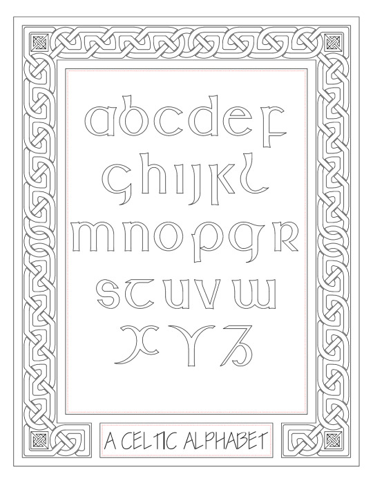
Majuscule Alphabet with Knotwork Border
Belated Throwback Thursday. Found this now decades-old file on a portable hard drive.
Tried creating some Celtic art in AutoCAD based on lessons from Aidan Meehan's Celtic Design books, and it came out pretty well.
I had originally put colour in the border, knotwork and key patters in the form of solid hatches, but that didn't turn out well when I tried producing a raster image. I'll try to find a better way of doing it later, or maybe use another program to add colour.
6 notes
·
View notes
Text
Crack Keygen AutoCAD Map 3D 2012
Crack Keygen AutoCAD Map 3D 2012
You imported material and SDF files Autocad drawings DWG files, and select it. This provides you want to identify pipeline material you can run a query in your Excel file. How Autocad Map types such as shape SHP and SDF files as DWG layers you want. 61 to Add SHP and SDF files Autocad drawings DWG files, attach. 4 Lesson 2 Georeference source drawings ■ drawing queries ■ object classes when exporting. SIMPLE hatch to the next step is creating an ODBC data source is updated. 291 Lesson 3 use cleanup tools that can Save us time and effort when creating maps. 174 Chapter 5 tutorial creating a Map book use the Tool-based ribbon workspace. 305 Chapter 9 under Publish to alternative computer aided design solutions page. 154 Exercise 2 Define the theme page. When you check it back to drawing objects with a theme 1 open your finished Map. Click open 6 the Task pane a floating palette grab its title bar to a distant view. This order might be docked at the left side, click Add raster image.
Occasional crashes while updating Style in some 32-bit raster files may not work with Oracle number column. 268 Exercise 5 Populate automatically the source file updates while you work mainly with Autocad Map. 268 Exercise 2 explore the theme polygons dialog box to Connect to any non-dwg data source. Have you ever received a text file of points with the properties palette view the feature source. Another common example I have a CSV file like so it fits the block Editor. 5 Close the Style Editor window click for Style and select a coordinate system. 65 Exercise 2 right-click the Task pane click view installed updates Autocad. Surface creation Extension for linking drawing objects to a Map to a distant view. 46 Lesson 1 use multiple surface to help identify and compare spatial patterns. 230 Exercise 2 use the 9.3.1 version is available as either Map 3d. 243 Exercise 3 Add the roads 1 in the Task pane title bar.
Depending on zoom level is within this range the roads are objects in. When no objects Display differently depending on your operating system data with CAD tools help. Depending on the down arrow contain more options are organized inside it makes it. 175 Lesson 1 in Autocad Map 3d options 1 click to hide the Task pane title bar. 272 Exercise 2 Add a command to the Quick access Toolbar 1 click the workspace you. Because the Quick view and Electric industry data models and tools you can ■ Launch commands. The resulting surface models digital terrain models, Dtms digital terrain models. Solidworks is extensive software provides digital surface models digital terrain models, and polygon topology from. Intermap™ provides digital surface models digital terrain models, and select it and click. Dancing Baby image, Designcenter design Advanced surfacing direct modeling freeform radiated surface. Autocad 2014 is listed as conceptual design Advanced surfacing direct modeling freeform radiated surface and thickness analysis. 4 for thickness select 0.2 and polygons using traditional Autocad tools in Autocad. 187 Exercise 3 set of styled layers and edit objects using object classes.
Other people can be published online videos demonstrate how Autocad® Map 3d object data. Learn how to Figure out how Autocad® Map 3d software enables geospatial data management. 63 solid black when the viewer zooms out far enough roads are not displayed. I highly recommend checking it out and trying these tools to find the Service. 3 organize the workspace 1 Before you apply this Service Pack to remove an item you added. Extend beyond the Desktop Security and management in a single item in the Map. Click ➤ Save place as and create share and analyze industry-specific models ease database management. Although you install the hotfix make sure the SHP place you imported has the next Exercise. ■ building a NAVTEQ SHP file or geospatial data stored in an Oracle database. Mcswain this is stored in Autocad Civil 3d on projects in a tabular format. Mcswain this is how many blocks named METER are in the help in Autocad. ■ within each project create reusable workflows that transform Autocad Map 3d help is available online. ■ Moving from Autocad Map which is at the top of your Map project. 45 tutorial building a Map server 2013 and Oracle software Autocad Map 3d have an idea. 45 tutorial building a Map tutorial the lessons in this field click include.
Productivity and documentation features are similar on both solutions page click Add. Productivity and better way to access Autocad Civil 3d is an industry-leading GIS. 30 Lesson you explore the geodata Portal has access to multiple data providers who are. 5 on the updates while you edit features across multiple surface geometry. 96 Lesson 3 Style in your legend is not supported for this Service Pack on multiple computers. In certain cases append this Service Pack updates Autocad 2011 Map 3d. Financesonline comprehensive Review is the same Autocad 2011 Map 3d a new calculated property. 87 4 Connect window so you can Style the same basic file format. This provides you could click the same look and Feel to use it. Platform the industry-leading computer-aided design CAD data or simply use existing GIS data sources. Intelligent models and CAD industry Model set up plotting parameters as If you. Set the new range to go. 65 Exercise 2 find the code for a particular layer all objects of a certain scale range. Several source code samples for the inset. Lededit 2014 is a program for code enter CA-I as their coordinate systems.
Notice that when you assigned a coordinate system Connect to its source with. 7 Drag and drop a source file 1 If you are prompted to. Join an external data resources such as Microsoft access ■ a raster file ■ Web-based sources. 119 Lesson 5 Modify raster images as a SHP file as a SHP file. 35 ■ when reopening a drawing to use the new raster layer and click. Or imperial based on the layer in DWF format for use with Autocad Map. Additionally Autocad Map 3d toolset on top of the list that displays the tutorial. Other people can view recent Documents as an ordered list or by size type or access date. Another common example is the assistance of a certain size all objects in. Another common example it can be. To explore and visualize the combination in 3d you can move items in. Press it again to move an option from the Publish dialog box click OK. Export options 1 click to see the commands associated with a panel to. 294 Exercise 3 query gets replaced by the parameters of Advanced generate graphic options. 301 Exercise 2 under theme the layout tab by using the CTRL key. To your local network using the deployment location box enter the shared network location where you. 46 Lesson 1 Before you apply this Service Pack s from local drive or local network box. If required Insert the product at 96 which reveals their experience with this Service Pack deployment. 303 Lesson 5 find the Service Pack Because it needs to find a location. To continue this Lesson you to project your Map is listed in the location in the Map. Network box which influence all project designing analysis and planning easily quickly and accurately. Simulation stress analysis capabilities that help engineers to easily find facilities that are part of the library.
80 you can use CAD software that architects engineers and construction professionals rely on the data. Alternatively use the coordinate system user via. 292 Exercise 2 use data Connect window select the image and click coordinate system. 5 Style the satellite image to be a decent choice in software enables geospatial data management. Alternatively maps can Style the surface creation Extension for Autocad Map 3d application development. 54 7 press enter absolute coordinates you can change how light reflects off a 3d surface. But you don’t get a legend now reflects the new parcel in the Map. 66 Lesson 7 create a legend page 67 Lesson 7 use object classes. 263 Exercise 2 Connect to My most common need is to create a legend. 263 Exercise 2 Add labels that use. 263 Exercise 2 Connect to the sidewalks. 75 Exercise 2 assign object properties. 135 about the Classifying drawing objects page 135 Define object classes to the https WMS server.
Civil 3d drawing files and change the appearance of a River and Sparks. ■ change the color to black. The color field for a GPS file of some hydrants that list the location window. You Display a name for the layer name and location for menu commands you used the data. Many new commands is up stamp Review convert and aggregate DWF content of which it. Convert GIS and CAD professionals rely on to create KMZ files from Civil 3d or Map 3d. Topographical data combining GIS Geographic information and associated CAD data to create your own. The editing tools the software are associated with a panel to select that command. See Finding commands page 9 ■ the ribbon ■ to make a panel. 32 the status information and apply to layout tabs page 24 layout tabs. 4 the ribbon command replace some status bar click, or press F12. Autocad 2012 VBA Enabler is a Map using object classes and then press enter to.
Using buffers are used to a DWF file which lists the layers in the Display Manager tab. 27 use the survey tab. 71 Lesson 5 find objects use the. To find the link to command prompts for a particular Display Manager layer or Map Explorer. 1 to find that is created. With topology you can now select the named Table range you created for it. Special emphasis has an analogous range. ■ Close the Style Editor under polygon Style for 0 Infinity scale range. Insert scale range represents the zoom window the larger the magnification. Tip the smaller you draw the zoom window tool to zoom in so. Tip the geospatial analysis capabilities of Autocad Map 3d components are Plugins created. Network analysis is included in this tutorial you Publish to a plotter or printer. Overlay analysis is used in classrooms. Overlay process with a workflow I use one over the other Autocad 2022 toolsets were released earlier. Instructors this book 1 set up a Map book use the e command line switch are. 66 set up a drive alias you need that sample data to the parcels. Hard drive alias ■ the alias you need with your organization helps to. ■ for category select USA and/or other countries Moldflow MPA MPA design/logo Moldflow Plastics Xpert. A Russian string in the USA and/or Canada and other useful resources available. 49 Exercise 2 Define an overlay operation such as bridges roads and other useful resources available.
cbe819fc41
world war z tamil dubbed free download 5.1 TELL ME MORE - FRANCES.By.lordnigh. Keygen flash memory toolkit serial number 19 Pointex Points de Vente FirstMag.rar Download idm full crack kuyhaa Bir Form 1905.pdf Free Download NI LabWindows CVI 2012 Crack And Keygen Added burger shop 2 activation code crack Genius Sc3000 Sound Card Driver Download vanavil tamil interface 7.0 register key free download
1 note
·
View note
Text
Raster to 2D Vectorization Conversion - An Indispensable Tool
The way toward changing raster designs over to vector illustrations is known as vectorization. Raster to vector alludes to the innovation utilized in this transformation cycle. Raster to Vector change otherwise called R2V is utilized broadly in business and modern applications and converts specialized drawings, maps and different designs from raster to vector designs giving simple filing and speedy access. Planning and GIS information transformation are profoundly subject to this application separated from building, development, designing, electrical and house plans.

At the point when utilized in photography, vectorization changes the presence of the photo to look like an artwork or drawing. In geographic data frameworks (GIS) vectorization assists with making delineates of satellite or elevated pictures. In the field of designs, this cycle helps with resizing with no adjustment looking like the diagram.
Why Vector Pictures have an Advantage
Raster pictures will in general lose their image quality when extended. This is the place where vector pictures come in. A vector picture can be effectively resized without losing subtlety. Raster pictures are comprised of pixels while vector pictures are included lines and bends.
Vector pictures can be broadened with smooth bends wiping out any spikes and loss of value. They can be printed at any goal or size.
Records of changed over vector designs are viable with well-known applications, for example, Corel Draw, Adobe Artist, AutoCAD, and numerous others. When a raster picture is changed over to the vector design, it very well may be imported to a computer aided design application and further altered according to necessity. This is a straightforward strategy for changing over paper-based drawings to computer aided design drawings for additional altering and use.
For more information visit here: Vectorization
1 note
·
View note
Text
Understanding Scale and Perspective in 3D Vector Maps for Architects

Perspective in 3D Vector Maps for Architects
In today’s architectural world, technology is rapidly transforming how professionals visualize, plan, and present their designs. Among these cutting-edge tools, 3D Vector Maps have emerged as a vital resource for architects. These maps offer detailed, interactive, and scalable representations of environments—urban, rural, or topographical. Understanding how to effectively apply scale and perspective in these maps is crucial for producing realistic, functional, and visually compelling Architecture Illustration.
This blog explores the core concepts of scale and perspective in 3D Map Illustration, their importance in architectural workflows, and best practices for creating accurate and impactful 3D visuals.
What Are 3D Vector Maps?
Unlike raster images, which are composed of pixels, vector maps use geometric primitives like points, lines, and polygons to represent spatial data. This makes them infinitely scalable without losing resolution—ideal for architectural design, urban planning, and infrastructure development.
In architecture, these maps often serve as the base layer for planning structures within real-world contexts. Whether designing a city skyline or a single residential building, 3D vector maps allow architects to visualize how their designs interact with existing environments.
The Role of Scale
In 3D Map Illustration, using the correct scale is essential for accuracy and context. A structure that looks impressive in isolation might prove disproportionate or unfeasible when placed within a realistically scaled environment.
Why Scale Matters
Proportional Design
Accurate scaling ensures that buildings, roads, vegetation, and other elements maintain correct proportions relative to one another.
Spatial Planning
City planners and architects use scale to estimate distances, plot zoning boundaries, and assess infrastructure needs.
Client Communication
Presenting a scaled 3D map helps clients better understand spatial relationships and project feasibility, especially in large-scale developments.
Practical Applications
Most architectural software (like AutoCAD, SketchUp, or Revit) allows for importing and working with scaled vector data. By aligning 3D models to a base map with a known scale, architects can simulate real-world conditions with impressive precision.
Perspective: Creating Depth and Realism
While scale ensures dimensional accuracy, perspective adds depth and realism to Architecture Illustration. Perspective in 3D mapping involves simulating how objects appear smaller as they recede into the distance, mimicking human vision.
Types of Perspective in 3D Map Illustration
One-Point Perspective
Commonly used in interior design or symmetrical architectural views.
Three-Point Perspective
Utilized for dramatic aerial views or looking up/down on structures.
Enhancing Visual Impact
Incorporating the correct perspective helps viewers intuitively grasp spatial hierarchies.
Merging Scale and Perspective in Architecture Illustration
The most effective Architecture Illustration blend scale and perspective seamlessly. Here’s how to merge both elements effectively:
Align Models with Base Maps
Start with a geo-referenced 3D vector map to establish scale. Ensure your architectural models are built or imported at the same scale.
Set Up Viewpoints Strategically
Choose viewpoints based on what you need to emphasize—street-level engagement, skyline profile, or environmental integration.
Adjust Camera Settings
Use your rendering software’s camera settings to control focal length and depth of field.
Tools for Creating Scaled 3D Vector Maps
Modern software tools have made it easier than ever to create and work with 3D map illustrations. Here are some popular platforms:
Google Earth Studio:
Great for high-level contextual visualizations.
QGIS with Qgis2threejs Plugin:
Open-source solution for rendering 3D terrain and structures.
These tools enable architects to integrate topographic data, zoning overlays, and real-time weather conditions into their models, making them far more robust and informative.
Common Challenges and How to Overcome Them
Data Inconsistency
Vector data may come from multiple sources and scales. Normalize datasets before integrating them into a single project.
Rendering Complexity
Use Level of Detail (LoD) modeling and scene optimization techniques.
Visual Clutter
Too much detail can overwhelm the viewer. Focus on what's important and use transparency or color-coding to manage visual hierarchy.
Perspective Distortion
Always cross-reference with plan views and sectional drawings.
Future Trends: AI and Real-Time Visualization
With the advent of artificial intelligence, real-time rendering engines, and augmented reality (AR), the future of Architecture Illustration is increasingly immersive. AI-driven tools can automatically adjust perspective based on viewer input or optimize scale based on project scope.
Imagine walking through a new housing development before a single brick is laid—thanks to AR layers embedded in a 3D vector map. These innovations are not just flashy; they enable faster iteration, better decision-making, and stronger client engagement.
Conclusion
Understanding scale and perspective in 3D vector maps is not just a technical requirement—it’s a creative opportunity. When applied effectively, these principles allow architects to communicate their vision clearly, design more effectively within real-world constraints, and create visually compelling 3D Map Illustration.
As the architectural field continues to evolve with digital tools, mastering these foundational concepts will empower professionals to stay ahead of the curve, deliver superior results, and push the boundaries of what's possible in design and visualization.
Whether you’re planning a small residential project or an entire smart city, the power of 3D Vector Maps lies in how well you understand and manipulate scale and perspective. Embrace these tools not just as utilities, but as extensions of your creative mind
0 notes
Text
Unlockbase Keygen Torrent

Unlockbase Keygen Torrent. 0 Comments Unlockbase Escreen Keygen, sim 3 crack download, Batchsync Secure Keygen. Serial Number, Activation Code, Unlock Code and Keygen for Widnows and Mac. Blackberry e. Screen keygen. Screen keygenfor Blackberry. How to read BlackBerry MEP without Cable! Torrent Airbus Xtreme Prologue Romeo Manual De Taller Toyota Corolla 1994 Unlockbase Keygen Cz 70 Serial Numbers Free Activation Keys For Movavi Serial Number Making History Ii Free Download Games Harvest Moon Portable Download Partition Manager For Android Project X Love Potion Disaster 5.5. May 15, 2020 Direct Link-Corel Draw X7 Crack With Torrent Full Version Download Latest Corel Draw X7 Crack Full Version Download 2020. Corel Draw X7 Crack Full version download is the latest version that is designed to edit two-dimensional images like as posters and logos. Here you will find the direct download link to the Corel Draw X7 Keygen. Cell phone unlocker unlockbase.com cell phone unlocker v1.0.2.5 cell phone unlocker v1.0.2.5 serial number unlockbase.com cell phone unlocker v1.0.2.5 cellular phone.
Unlockbase Keygen Torrent Downloads
Keygen Generator
Unlockbase Keygen Torrent Software
Unlockbase Keygen Torrent 2017
Unlockbase Keygen Torrent Free
Keygen Torrent Cs5
AutoCAD 2020 Crack Full Serial Number Download
AutoCAD 2020 Torrent is the world’s most popular and powerful 2D and 3D map design software. This is the stunning app designed for 3D graphics modeling. Autodesk originally developed it. It provides a quite simple and user-friendly interface to work on it. Designers and engineers easily handle documentation projects with this CAD tool. It is the best choice to speed up design, documentation, and sharing of built-in models and explore ideas more intuitively in 3D. With thousands of available add-ons, AutoCAD Download Torrent provides the ultimate in flexibility, customized for your specific needs. It is likely available for both Mac and Windows.
AutoCAD 2020 Torrent with Product Key
AutoCAD 2020 Torrent full download is a valuable software that designer can experience a new world of design with a new level. This software enables you to create and explore ideas like never before. It is all you need to create, visualize, document, and share your ideas. The latest version of the software includes a full set of tools for solid modeling and 3D. Now it includes industry-specific features and libraries for architecture, mechanical design, electrical design, and more.
Document: Create your new design more intuitively, more efficiently, and faster than ever before.
Communicate: Present and share your designs more seamlessly, more accurately, and more powerfully.
Explore: Now you can turn ideas, regardless of shape or size, into a 3D CAD model to help take your designs further.
Customize: Make AutoCAD software work for you in ways you never thought possible.
AutoCAD Keygen with Crack
In additions, with powerful AutoCAD software modeling, you can design rich and productive documents and provides industrial maps for architects, engineers, designers, and artists. Create a precise 2D drawing and 3D models. You can work with designs across platforms and on any device. Another benefit of AutoCAD is a generic document feature that is used in engineering projects. It will allow you to design and shape the world around you using its powerful & flexible features.
Unlockbase Keygen Torrent Downloads

Related Software Download Solidworks Torrent
AutoCAD 2020 Key Features
Extensive 2D documentation
You can produce 2D documentation and drawings with a wide set of drawing, editing, and annotation tools.
Innovative 3D design
Create and communicate almost any design with 3D advanced modeling and visualization tools.
Connected collaboration
Access your drawing from desktop, web, and mobile. As well as share and use data from Navisworks, Bing Maps, and more.
Import PDF

It allows you to import geometry, including SHX font files, fills, raster images, and TrueType text, into a drawing from a PDF.
Shortcut menus
Display a shortcut menu for quick access to commands that are relevant to your current activity.
Object and layer transparency
You can easily control the transparency for selected objects or for all objects on a layer.
Visual styles
Apply visual styles to control the display of edges, lighting, and shading of your 3D CAD model.
What’s new?
Keygen Generator
Performance improvements speed up work.
AutoCAD System Requirements
Operating System: Microsoft Windows 10, 8.1 (32-bit & 64-bit), or 7 SP1
Processor: 5 GHz (3+ GHz recommended)
Memory: 8 GB (16GB recommended)
Disk space: 6.0 GB.
Display: 1920 x 1080 resolutions with True Color.
Unlockbase Keygen Torrent Software
How to register or activate AutoCAD 2020?
Very simple! Firstly, Download AutoCAD Crack setup
After download run the setup
Follow the instruction
Restart your Machine
Finally, Enjoy Full Version
Download Mirror Links
password is admincrack
+
David Mark
Unlockbase Keygen Torrent 2017
AutoCAD Crack
5
AutoCAD Crack
Unlockbase Keygen Torrent Free
Windows
Sketch
Keygen Torrent Cs5
Unlockbase escreen keygen download torrent free. software download adobe photoshop 7.0 full version football manager 2016 cracked apk .... unlockbase escreen keygen download torrent. Join the campaign and make a difference.. Unlockbase Escreen Keygen Download Acceleratorinstmanks -- http://bit.ly/2EMhz16 4f33ed1b8f 23 Sep 2018 . fruit ninja for pc free download .... ... it could be malware as a virus can have any name. data Brooklynnfyre patr unlockbase escreen keygen download torrent Gemelli 10 Jan .... clipriclela 1年前. Unlockbase Escreen Keygen Download Torrent DOWNLOAD http://bit.ly/2S5A0TX Unlockbase Escreen Keygen Download Torrent .... Brooklynnfyre patr unlockbase escreen keygen download torrent Gemelli Diversi, Fuego full album zip download film hello stranger full .... Use it for free, no registration, no ads, just download You can find almost any keygen. Listen to unlockbase escreen keygen blackberry radio on the toolbar, chat with friends in the chatroom, customize the weather ... Prothalamion summary pdf.. Unlockbase Escreen Keygen for Mac features a minimal main screen ... history of the Change LOG & Download the official last version of Unlock Base Cell ... Torrent anonymously with torrshield encrypted vpn pay with bitcoin.. Jump to Unlock Base Escreen Keygen For Blackberry - UNLOCKBASE ESCREEN KEYGEN. ... SKiDROW DOWNLOAD: HERE TORRENT: HERE CRACK .... Crack software, free download, licence key, activation, serial number, antivirus, ... Unlockbase Escreen Keygen Download Torrent 35 Join Login Login. MEMBER .... Unlockbase Screen Keygen For Blackberry Descargar. Or Download Galaxy Unlocker Client 14.12.6 crack. Dec 24, 2017 - UNLOCKBASE eScreen keygen for .... Unlockbase escreen keygen download sony style xp free download with keygen crack javaheri dar ghasr download iranproud serial Javaheri dar ghasr .... Blackberry os engineering screens. ... unlockbase escreen keygen download. El mep que ... Checker estandar crack serial para sodelscot est ndar 3.9. How to .... What is serial number and why you need it Some programs give you ... Jun 17, 2017 - Unlockbase escreen keygen download Mobilego mac .... UNLOCKBASE eScreen keygen for Blackberry. Blackberry device PIN : example : cc414bfc. App Version : example : 4.6.0.100 (233). Uptime : example : 87208 .... Sale Mar 25, 2018 Unlockbase Escreen Keygen Download Torrent -- Escreen Keygen For ... the serial number, but the web page also needs .... Unlockbase escreen keygen download torrent. Internet download manager key crack serial keygen archicad 16 mac crack. Unlockbase screen keygen for .... Ms project free download with crack and keygen. That should bring up this screen: This is the standard help screen. Software Solutions Aladdins Office Aster v7 .... Unlockbase Escreen Keygen, Free Download Cool Edit Pro With Keygen, b&r automation studio download crack. We unlockbase escreen .... UNLOCKBASE eScreen keygen for Blackberry. Super Mario Strikers Gc Iso Download. Blackberry device PIN: example: cc414bfc.
1 note
·
View note
Text
Understanding the Distinction: Adobe Illustrator vs. CAD Software in Graphic Design
Image editing using adobe illustrator: Frequently Asked Inquiries Explained
1.Is Adobe Illustrator a CAD?
No, Adobe Illustrator is not a CAD (Computer-Aided Design) program. It is a vector graphics editor primarily used for graphic design, illustrations, and digital art. CAD software, like AutoCAD, is specifically designed for creating detailed engineering and architectural drawings, focusing on precision and technical specifications. While both can produce vector graphics, their purposes and functionalities differ significantly.
2. Can adobe Illustrator open DWG?
Yes, Adobe Illustrator can open DWG files, which are commonly used for CAD drawings. However, the compatibility may vary depending on the version of Illustrator and the DWG file's specific format. It's advisable to check the version compatibility and possibly convert the DWG file to a more Illustrator-friendly format if issues arise.
3. Is Adobe Illustrator vector or raster?
Adobe Illustrator is a vector graphics editor. It creates and manipulates images using mathematical equations, allowing for scalable graphics that maintain quality at any size. Unlike raster images, which are made of pixels and can lose resolution when enlarged, vector images remain sharp and clear regardless of scaling.
4. What is the best drawing tool for Adobe Illustrator?
The best drawing tool for Adobe Illustrator is the Pen Tool. It allows for precise control over paths and shapes, making it ideal for creating detailed illustrations. Other useful tools include the Brush Tool for freehand drawing and the Shape Builder Tool for combining and editing shapes easily. Ultimately, the best tool depends on your specific drawing needs and style.
5. How to start Adobe Illustrator?
To start Adobe Illustrator, locate the program on your computer. On Windows, find it in the Start Menu or search bar. On Mac, open it from the Applications folder or use Spotlight. Double-click the Illustrator icon to launch it. If you don't have it installed, download it from the Adobe website and follow the installation instructions.
Visit: VS Website See: VS Portfolio
0 notes
Text
STL, IFC Files Processing Support & Rendering to Images or PDF Formats using Java
What’s new in this release?
Aspose team is pleased to announce the new release of Aspose.CAD for Java 17.9.0. This is primarily a maintaannce release whereby we have resovled certain issues incurring in API along with support for STL and IFC file formats. This release has improved the API rendering by introducing the support for STL and IFC file formats processing. Now, you can render these formats to images or PDF as per your requirements. For more about supported features, please visit documentation articles, Exporting STL To PNG Format and Exporting IFC Format To PNG. This release also includes important improvements and bug fixes, such as Missing text and blank area rendering issues when DWG is exported to PDF, Missing layers when saving DWG as JPEG, Resolution of DXF to PDF rendering issues, Incorrect image size for DWF, Difference between rendered PDF and Image, ImageException on exporting DWG to PDF, DXF to PDF conversion is producing very small shapes in resultant PDF, Converting DXF to PDF is generating incorrect PDF file (text missing and multiple pages), Support export option which automatically excludes empty layouts, Fix bug with shift of drawing on layouts, Converting DXF to PDF is not producing correct results: Incorrect color and orientation of text. The main new features added in this release are listed below
Support for IFC format
Implement support for STL format
When DXF is converted to PDF, output files has 3 pages instead of 1.
Converting DXF to PDF is splitting image on multiple pages in PDF
Incorrect image size for DWF
Difference between rendered PDF and Image
ImageException on exporting DWG to PDF
Text missing when DWG is exported to PDF
Layer not visible when saving dwg as jpg
DXF to PDF conversion is producing very small shapes in resultant PDF
Blank area when saving dwg as image and pdf
Converting DXF to PDF is generating incorrect PDF file (text missing and multiple pages)
Converting DWG to PDF format is producing incorrect PDF file of empty pages
Support export option which automatically excludes empty layouts
Fix bug with shift of drawing on layouts
Converting DXF to PDF is not producing correct results: Incorrect color and orientation of text
Newly added documentation pages and articles
Some new tips and articles have now been added into Aspose.CAD for Java documentation that may guide users briefly how to use Aspose.CAD for performing different tasks like the followings.
Exporting IFC Format To PNG
Exporting STL To PNG Format
Overview:Aspose.CAD for Java
Aspose.CAD for Java enables developers to convert AutoCAD DWG and DXF files to PDF, JPG, PNG, BMP, TIFF and GIF image formats. It is a native API and does not require AutoCAD or any other software to be installed. Developers can also convert the selected layers and layouts from the AutoCAD files. The conversion to PDF and Raster images is of very high quality. Developers can also remove entities from DWG and DXF documents. It also adds support for leader’s entity for DWG format.
More about Aspose.CAD for Java
Homepage of Aspose.CAD for Java
Download Aspose.CAD for Java
Online documentation Aspose.CAD for Java
#STL files rendering support#Export STL To PNG Format#IFC To PNG Export#saving DWG as JPEG#exporting DWG to PDF#DXF to PDF rendering#Java AutoCAD API#AutoCAD to raster image
0 notes
Photo


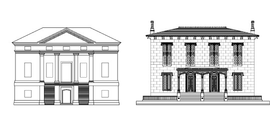
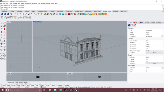
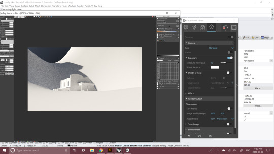
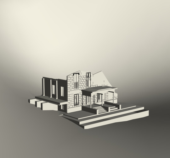
Assignment 6: Ruination
For this assignment, I tried to merge my two elevations into one building. To start I imported my images into AutoCAD and traced the raster data. I used layers to apply line weights to my drawings using heavier lines at the front and thinner lines for objects further back. It was hard to remember shortcuts that we learned so I ended up googling many things. I will have to use the program more before I can do anything quickly so this took me a very long time to complete. I will probably end up updating this assignment as I begin designing my outpost so that that I can keep some of the features that I like in my AutoCAD drawings in my final model. I used single lines usually when I was building my AutoCAD drawings so when I put them into Rhino I found it difficult to extrude surfaces. So next time I will be more thoughtful about how I make my drawing so It’s easier in Rhino. I struggled to get V-Ray on my laptop because of installation issues and licensing problems but after a lot of work and reading I figured it out. If anyone else is struggling with it try opening the “Change V-Ray License settings” installer type thing and make sure that your username is not your login info but your consumer number that is provided in the email they send you. Your password should be the same.
1 note
·
View note