#fea simulation
Explore tagged Tumblr posts
Visit Tumblr Blog
Explore Tumblr blogs with no restrictions, modern design and the best experience.
Last Seen Tumblr Blogs


Fun Fact
The Tumblr office adopted Tommy, an 11-year-old Pomeranian.
Text

Enhance Product Design with FEA Simulation Software for Accurate Analysis
Looking to optimize your product design with precision? FEA Simulation Software, like Inventor Nastran, offers advanced tools for accurate finite element analysis, allowing you to predict and solve real-world challenges before production. With its extensive simulation capabilities, you can ensure structural integrity, reduce material costs, and enhance product performance. Discover how FEA simulation can transform your design process with comprehensive insights and reliability. Visit our landing page to learn more about implementing FEA Simulation into your workflow and achieving superior results.
0 notes
Text
Unlock deeper insights and optimize your designs with our expert Finite Element Analysis services. ⚙️ Ensure product performance, predict behavior, and reduce costly prototypes. Ready to elevate your engineering?
👉 Learn how FEA can transform your projects.
#FEA#FiniteElementAnalysis#EngineeringAnalysis#Simulation#ProductDesign#Innovation#TeslaMechanicalDesigns
1 note
·
View note
Text
CAD/FEA Engineering Services: Optimizing Product Design and Performance with Advanced Simulation

In today's rapidly evolving engineering landscape, Computer-Aided Design (CAD) and Finite Element Analysis (FEA) have become indispensable tools for product development and optimization. These technologies enable engineers to create detailed digital models and simulate real-world conditions, leading to more efficient and reliable designs.
Understanding CAD and FEA
Computer-Aided Design (CAD):
CAD involves the use of software applications to create precise 2D or 3D models of physical components. Tools like AutoCAD, Inventor, SolidWorks, and Creo facilitate the development of detailed geometric representations, allowing for comprehensive visualization and modification of designs before physical prototypes are made.
Finite Element Analysis (FEA):
FEA is a computational technique used to predict how products react to real-world forces, such as heat, vibration, and other physical effects. By breaking down complex structures into smaller elements, FEA software can simulate and analyze the behavior of each component under various conditions, providing insights into potential performance issues.
The Synergy of CAD and FEA in Engineering
Integrating CAD and FEA engineering services allows engineers to design and analyze products within a unified digital environment. This integration streamlines the development process, enabling rapid iterations and refinements based on simulation results. For instance, a design created in CAD can be directly imported into FEA software for stress analysis, facilitating immediate feedback and optimization.
Applications Across Industries
The combined use of CAD and FEA spans various industries, including:
Aerospace: Designing and analyzing flight control systems and structural components to ensure safety and performance.
Automotive: Optimizing vehicle structures for weight reduction while maintaining structural integrity.
Manufacturing: Developing machinery and equipment with enhanced durability and efficiency.
Benefits of CAD/FEA Engineering Services
Engaging specialized CAD/FEA engineering services offers several advantages:
Cost Reduction: By identifying potential design flaws early through simulation, companies can avoid costly physical prototypes and rework.
Improved Performance: Simulations enable the optimization of designs for better performance under specific conditions.
Accelerated Time-to-Market: Streamlined design and analysis processes lead to faster product development cycles.
Servotech Inc.: Expertise in CAD/FEA Design and Analysis
Servotech Inc. specializes in providing comprehensive CAD/FEA design and analysis services. Utilizing advanced software tools, their team designs mechanical systems with 3D solid modeling, ensuring adherence to geometric dimensioning and tolerancing standards. They integrate these designs with FEA software to simulate conditions such as stress, temperature, and fluid dynamics, offering clients precise and efficient engineering solutions.
Conclusion
The integration of CAD and FEA in engineering services by Servotech has revolutionized the way products are designed and analyzed. By leveraging these technologies, companies can achieve optimized designs, reduce costs, and accelerate development timelines. Servotech Inc.'s expertise in this domain exemplifies the benefits of adopting advanced simulation tools in modern engineering practices.
#CAD#FEA#EngineeringDesign#ProductDevelopment#FiniteElementAnalysis#3DModeling#Simulation#StructuralAnalysis#MechanicalEngineering#ServotechInc
0 notes
Text
youtube
Linear algebra is more than just numbers and equations—it's the backbone of modern engineering and technology! From solving systems of equations to enabling advanced cryptography, linear algebra finds its way into diverse applications like CFD, FEA, and even creating stunning visuals on your screen.
In this video, we’ll explore the fundamental concepts of linear algebra, including vectors, matrices, and linear transformations, and demonstrate how they’re applied in real-world scenarios like encryption and engineering simulations.
Dive into the world of numbers, transformations, and their powerful implications across engineering and technology!
If you’re interested in speaking with our experts from Scania, Mercedes, and Nissan, and scheduling a personalized career plan, call us at +91-9342691281 or register here: https://bit.ly/4gzFdOJ
0 notes
Text
Precision and Innovation: Exploring the Role of Engineering Design and CAD Drawing Services
Imagine constructing a skyscraper or designing a complex machine without a detailed plan. This is where Engineering Design Services come into play, transforming abstract ideas into detailed blueprints. These services are essential in laying the groundwork for successful engineering projects, ensuring every aspect is meticulously planned and executed with precision.

Strategic Impact of Engineering Design Services
In the competitive world of engineering, Engineering Design Services provide a significant edge. They refine not only the aesthetic appeal of a project but also its functionality and sustainability. By collaborating with clients and stakeholders, these services ensure that every element of a project aligns with technical specifications and overall vision, setting the stage for successful implementation and long-term success.
The Role of CAD Drawing Services in Modern Engineering
Once the design phase is complete, the focus shifts to detailed visualizations provided by CAD Drawing Services. These services are indispensable in modern engineering, allowing for the creation of precise and detailed drawings. By visualizing every component in three dimensions, engineers and architects can ensure that all parts fit together seamlessly, reducing the risk of errors during the construction phase.
Enhancing Precision with CAD Drawing Services
The advancements in CAD Drawing Services have revolutionized the way engineering projects are visualized and executed. These services allow for the manipulation of intricate 3D models, providing a virtual simulation of the final product. This not only enhances the precision of the design but also allows for modifications to be made easily, ensuring that the final product meets all requirements and standards.
Navigating Future Challenges with Advanced Design Techniques
As technology continues to evolve, the integration of AI and machine learning with Engineering Design Services is becoming increasingly important. These advanced techniques provide predictive insights and automated design adjustments, which are crucial for managing complex projects. Similarly, CAD Drawing Services are evolving to include virtual reality and augmented reality, offering immersive experiences that allow for better design comprehension and client engagement.
Ensuring Compliance and Global Standards
In the evolving landscape of global industries, adhering to international standards and regulations is crucial for success. Engineering Design Services and CAD Drawing Servicesplay a pivotal role in ensuring that projects meet these stringent requirements. By incorporating global best practices and standards into the design and drafting processes, these services help companies expand their reach and maintain competitiveness in international markets. This focus on compliance not only ensures safety and quality but also enhances the credibility and reputation of businesses in the global arena.

Conclusion
In a world where precision and efficiency are paramount, the roles of Engineering Design Services and CAD Drawing Services are more critical than ever. For businesses looking to leverage these advanced services, visitingfeamax.comoffers a gateway to industry-leading expertise and innovative solutions. Whether it’s refining a complex design or ensuring that every component fits perfectly, the right design services can transform potential into reality, driving success in every project.
Blog Source URL :
#Computational Fluid Dynamics Consulting#CFD Consulting Services#Cad Design Services#Computer Aided Design Services#Engineering Design Services#Cad Drawing Services#FEA Consulting Services#Finite Element Analysis Consultants#FEA Simulation Services#Engineering Manufacturing Services#Manufacturing Sourcing Services#Mold Flow Analysis#Moldflow Service#Moldflow And Casting Analysis
0 notes
Text
TEFUGEN: Redefining Engineering Excellence through Finite Element Analysis
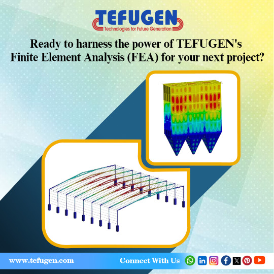
WHY USE FEA IN YOUR ENGINEERING PROJECTS?
At the forefront of engineering excellence, TEFUGEN offers exceptional Finite Element Analysis (FEA) services in India. Utilizing FEA yields unparalleled benefits, offering profound insights into your project's performance prior to physical model construction. It aids in pinpointing stress points, identifying potential weaknesses, and assessing material durability under diverse conditions, effectively mitigating the risk of failure and associated costs. With its ability to conduct precise simulations, FEA empowers informed decision-making in design modifications, guaranteeing optimal performance and safety.
Structural Integrity Assessment:
In engineering, FEA, an indispensable method, meticulously assesses structural integrity by simulating material responses to diverse conditions. This predictive analysis is pivotal for guaranteeing the safety and reliability of designs. TEFUGEN, as a FEA consulting service in India, provides expert assistance, enabling engineers to identify potential weaknesses and optimize for durability.
Thermal stress analysis:
FEA analysis services play a key role in assessing heat distribution within structures or components. Engineers leverage this analysis to model and analyze thermal behavior meticulously. By doing so, they optimize designs for efficient heat dissipation or retention, ensuring the performance and reliability of the system. This detailed analysis enables engineers to make informed decisions regarding material selection, insulation, or heat management strategies, ultimately enhancing overall system efficiency and longevity.
Mechanical Component Design:
FE Analysis plays a crucial role in optimizing mechanical component design by accurately predicting stress, strain, and deformation. This ensures components can effectively withstand operational loads while minimizing material usage, thereby enhancing efficiency and cost-effectiveness.
Fatigue Analysis:
Engineers use FEA for fatigue analysis, predicting the lifespan of components subjected to cyclic loading. This is crucial in industries like aerospace and automotive, where understanding material fatigue is paramount.
Fluid Structure Interaction:
Fluid Structure Interaction (FSI) is a crucial aspect of FE Analysis, examining the dynamic interaction between fluids and structures. By simulating how fluids affect nearby structures and vice versa, FSI enables engineers to optimize designs for enhanced performance and durability across various industries.
Modal analysis Modal analysis using FEA techniques enables the simulation of eigenfrequencies and eigenmodes, revealing the vibrational characteristics of a structure. Meanwhile, harmonic analysis facilitates the emulation of peak responses to specific loads, offering insights into system behavior. These analyses are indispensable tools for understanding structural dynamics and optimizing performance.
Motion study Unlocking insights into structural behavior through Finite Element Analysis (FEA) motion studies. Discover the intricate dynamics of systems, optimize designs, and ensure structural resilience with FEA motion analysis.
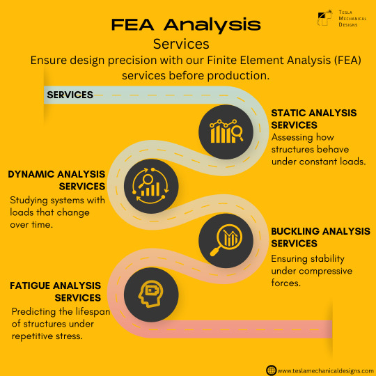
#Finite Element Analysis Consulting Services in India#FEA Analysis Services#FEA Consulting Engineers#FEA Consultants in Trichy#FEA#Finite Element Method#Structural Analysis#Stress Analysis#Static Analysis#Dynamic Analysis#Thermal Analysis#Fluid Flow Analysis#Vibration Analysis#Fatigue Analysis#Buckling Analysis#Modal Analysis#Meshing#Boundary Conditions#Material Properties#Convergence#Post-processing#Optimisation#Mesh Generation#Simulation Software
0 notes
Text

ABAQUS Software – Finite Element Analysis - PIGSO LEARNING
Abaqus is a complete Abaqus environment that provides an interface for creating, monitoring, and evaluating results from Abaqus/Standard and Abaqus/Explicit simulations. Abaqus/CAE is further divided into modules, where each module defines the aspect of the modelling process like defining the geometry, defining material properties, and generating a mesh.
ABAQUS - Simulation Analysis Software
CAE is a common graphical user interface that is used for modelling, solving, and post-processing a finite element problem.
The steps involved in the construction of a model are explained below-
ABAQUS Solver
ABAQUS Standard is an implicit solver used to solve nonlinear problems.
ABAQUS Explicit used for solving dynamics/wave propagation problems.
Part Module
Part Module Is the first step towards creating a model as parts are the building blocks of an Abaqus/CAE model. Part can be created in the following ways: Create the part using the tools available in the Part module. Import the part from a file stored in a third-party format. Import the part (mesh) from an output database. Import a meshed part from an input file.
You use the Part module to create, edit, and manage the parts in the current model. The Part module allows you to do the following:
Property Module
You can define the properties of a part or part region by creating a section and assigning it to the part. In most of the cases, sections refer to the materials that you have created. A material definition specifies all the property data relevant to a material. You can specify a material definition by including a set of material behaviours, and you supply the property data with each material behaviour you include. Each material that you create is assigned its name and it is independent of any particular section. Abaqus/CAE assigns the properties of a material to a region/section of a part when you assign a section referring to that material that you have created to the region.
Assembly
You can use the Assembly module to create and assemble the assembly. A model contains one main assembly, which is composed of instances of different parts from the model as well as instances of other models. An instance maintains its association with the original part/model. If the geometry of a part changes, Abaqus will automatically update all instances of the part and changes will be reflected in the model. You can’t edit the geometry of an instance directly. Your main model can contain many parts and model subassemblies, and a part or model can be instanced many times with the main model assembly; however, a model contains only one main assembly. Loads/boundary conditions are all applied to the complete assembly.
Even if your model consists of only a single part, you have to create an assembly that consists of just a single instance of that part. A part instance can be a representation of the original part. You can create either independent or dependent part instances. An independent instance is effectively a clone of the part. A dependent instance is only a pointer to the part or virtual topology. You cannot mesh a dependent instance.
Step
Within a model, you can define a sequence of one or more analysis steps. The step sequence provides a convenient way to capture changes in the loading and boundary conditions of the model, changes in the way parts of the model interact with each other and any other changes that may occur in the model during the analysis.
Interaction
Interactions are step-dependent objects, which means that when you define interactions, you must indicate in which steps of analysis they are active. The Set and Surface toolsets in the Interaction module allow you to define and name the model to which you would like interactions and constraints to be applied. Abaqus does not recognize the mechanical contact between different part instances of an assembly unless the contact is specified in the Interaction module.
Load
Load is an independent module as Abaqus cannot apply load automatically; you have to select the load type and position on which load is to be applied. You can apply load to any node/Surface. You can use the Load module to define and manage the following prescribed conditions:
Loads
Boundary conditions
You can apply different types of loading
Concentrated force
Moment
General and shear surface traction
General shell edge load
Inertia relief
Current density
Boundary Conditions
Boundary Conditions is also an important module to check the specific point interaction. As Abaqus cannot apply real-life constraints in the model. So you have to manually specify the predefined condition to be applied to a model to make analysis more effective and accurate
Mesh
The Mesh module allows you to generate meshes on parts and assemblies created within Abaqus. Various levels of automation and control are available so that you can create a mesh that meets the requirements of the analysis model. As with creating the parts and assemblies, the process of assigning mesh attributes to the model such as seeds, mesh techniques, and element types is feature-based.
The Mesh module provides the following features:
Tools for prescribing mesh density and global levels.
Model colouring indicates the meshing technique is successful and assigned to each region in the model.
A variety of mesh controls, such as:
Element shape
Meshing technique
Meshing algorithm
Adaptive remeshing rule
Optimization
Optimization Is a process that generates results and analysis. You must combine the optimization results into an individual output file to view the results of the optimization in the Visualisation module (Dassault).
Job
Job In the job module we create a job Check job from the job manager by “Data Check” If no error is reported Submit the job Check results in the Visualization Module
Visualisation
Abaqus Training
You find the best training platform to learn Abaqus Simulation Software Online by the PIGSO LEARNING company. You can get trained from the very basics to advanced levels of simulation analysis for different types of industrial categories like Structural, Mechanical, Geotech, Aerospace and Automobile engineering. Abaqus Training online course helps you to explore the software and get trained. Its help in your research work and career boost.
0 notes
Text
CHATGPT DOESNT EVAPORATE WATER
LOOK AT ME IN MY EYEBALLS CHATGPT USES WATER COOLED SERVERS IN THE SAME MANNER AS HOSTING A WEBSITE OR RUNNING FEA SIMULATIONS AND USES THE SAME OR LESS AMOUNT OF POWER AND COOLING AS THESE THINGS. START FEARMONGERING ABOUT HOW EVERY TIME YOU CLICK AN AMAZON LINK YOURE EVAPORATING WATER OR SHUT UP
THE POSTS YOURE PUTTING ON MY DASH ABOUT CHATGPT EVAPORATING WATER ARE FUCKING STUPID AND WRONG CUT THAT SHIT OUT
#listen i know i made a joke about having luddite tendencies literally yesterday but you have to know youre factually fucking wrong when#youre being like that. ok. you can be annoyed that chatgpt exists but you have to fucking know youre being unreasonable
3 notes
·
View notes
Text


A center-locking version of our original VV1R 5-lug wheel, the VV1R-CL features a sharp Y-spoke design with integrated machining details at the base of each spoke, striking angles, and deep concave profile. The Forgeline VV1R-CL is a fully-forged one-piece monoblock wheel that utilizes manufacturing technology similar to our legendary GS1R wheel and is engineered to allow plenty of room for caliper clearance and extreme brake fitment. The VV1R-CL’s one-piece monoblock forging and computer-simulated FEA design process combine to produce a wheel that is lightweight, stiff, and has excellent fatigue strength. Made for hardcore track use, the Forgeline VV1R-CL is engineered with a 2100+ lb. street tire load rating to handle serious motorsport applications. The VV1R-CL is currently available in 18-inch, 19-inch, 20-inch, 21-inch, and 22-inch diameters with a range of widths and offsets. It can be made to accommodate most centerlock applications and can be made with knurled beads. (Please Note: Depending on size, the VV1R-CL may be available in deep, medium, or shallow concave profiles.) And just like any Forgeline wheel, the VV1R-CL is available with fully customizable finish options. Learn more (including sizes and pricing) at: https://forgeline.com/wheel/vv1r-cl
🇺🇸🇺🇸🇺🇸
#forgeline#forgelinewheels#forgedwheels#customwheels#forgedmonoblock#VV1RCL#ForgelineVV1RCL#centerlock#notjustanotherprettywheel#doyourhomework#madeinUSA#PRIShow#PRI2023
8 notes
·
View notes
Text

Can FEA Simulation be used to optimize the design of our product?
FEA Simulation, Use a Wider Variety of Study Types and Materials in Your Analysis.The ease of doing business becomes a valuable factor in empowering engineers and analysts to make great products. Autodesk Inventor Nastran® delivers finite element analysis (FEA) tools for engineers and analysts. Simulation covers multiple analysis types, such as linear and non-linear stress, dynamics and heat transfer.Inventor Nastran provides precise and dependable FEA solver solutions that are widely accepted in the industry inside your CAD environment.
0 notes
Text
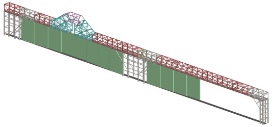
Structural Design and FEA Simulation of Aircraft Hangar Outrigger Door Structure
The structural design and simulation of an aircraft hangar outrigger door are pivotal in ensuring the reliability and safety of this essential part of the hangar infrastructure. In this blog, we explore the technical aspects of the design and finite element analysis (FEA) simulation of such structures, with a focus on optimizing performance, ensuring durability, and meeting stringent safety standards.
Overview of Aircraft Hangar Outrigger Door Structure
An outrigger door is typically designed as part of large hangar facilities, providing additional clearance for the aircraft. Its design must withstand the operational loads and environmental conditions, ensuring longevity and minimal maintenance.
Key Structural Components:
Trusses: Large trusses (e.g., TRUSS-1 to TRUSS-5 as indicated in design layouts) form the backbone of the structure, distributing loads efficiently.
Vertical Columns: These columns, often consisting of robust materials, support the trusses and provide vertical stability.
Rails and Supports: The top and bottom rails, supported by various beams such as NPB (narrow parallel flange beams) and ISMB (Indian Standard Medium Beams), guide the door’s movement and secure the structure.
These components, made of high-strength steel, are interconnected with bracing and rib structures to provide both rigidity and flexibility under load.
Structural Design Considerations
The design of the outrigger door must account for several factors, including:
Load Distribution: The door structure should evenly distribute loads, including the weight of the door itself and dynamic forces from wind or operational activities.
Material Selection: High-strength steel, such as ISMB beams, is often used for its ability to handle the high loads and dynamic stresses encountered during the door’s operation.
Space Optimization: As seen in the design, dimensions and spacing of the trusses, vertical columns, and rails are meticulously calculated to ensure space efficiency without compromising structural integrity.
Thermal and Environmental Stresses: The door must withstand environmental factors such as temperature variations, wind loads, and possible seismic activity.
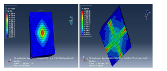
Finite Element Analysis (FEA) for Structural Integrity
FEA is a crucial step in validating the design of the outrigger door structure. By simulating real-world conditions, engineers can predict how the structure will perform under various loads and stresses.
FEA Simulation Process:
Model Creation: A 3D model of the door structure is created based on the design drawings, including all trusses, columns, and rails.
Material Properties: The material properties (elastic modulus, yield strength, etc.) are input into the simulation software to ensure accurate behavior during loading.
Meshing: The structure is divided into small elements for analysis. A finer mesh may be applied to critical areas like the junctions of trusses and vertical columns, where stress concentrations are expected.
Boundary Conditions: Realistic boundary conditions, such as fixed supports at the base of the columns and loading from the door’s operation or environmental forces, are applied.
Load Cases: Various load cases, including dead load (structure’s weight), live load (operational forces), and environmental forces (wind, seismic), are simulated to analyze the stress and deformation of the structure.
Results and Optimization
The FEA simulation results are used to assess:
Stress Distribution: The software highlights regions with high stress concentrations. If the stress exceeds material limits, design modifications are made to redistribute the load.
Deformation: Excessive deformation, especially in the rails or trusses, can affect the door’s function. The simulation helps ensure that deformations remain within acceptable limits.
Factor of Safety: A critical outcome of the analysis is ensuring that the design meets the required factor of safety, accounting for uncertainties in loading conditions and material properties.

Conclusion
The structural design and FEA simulation of an aircraft hangar outrigger door structure are essential processes in ensuring the reliability and safety of the door system. By combining robust design principles with advanced simulation techniques, engineers can create a structure that withstands operational and environmental challenges while maintaining optimal performance throughout its lifecycle.
This detailed approach not only ensures compliance with safety standards but also reduces the risk of future structural failures, ensuring smooth operations for the aircraft hangar facility. Graphler Technology Solution provides CFD Analysis services, Engineering Animation services, stress analysis services and structural design services They have well expertise team with 10 yrs of industrial knowledge. Partnering up with the best structural analysis services provider or top product design companies will help you to discover new ideas.
0 notes
Text
Finite Element Analysis (FEA) Engineering Services: Enhancing Product Development and Structural Integrity

Finite Element Analysis (FEA) has become an indispensable tool in modern engineering, enabling the simulation and analysis of complex structures and systems under various conditions. By breaking down intricate geometries into smaller, manageable elements, FEA allows engineers to predict how products will react to real-world forces, vibrations, heat, and other physical effects. This article delves into the significance of FEA engineering services, their applications, benefits, and the process involved, with a particular focus on the offerings of Servotech Inc.
Understanding Finite Element Analysis (FEA)
FEA is a computational technique used to approximate the behavior of physical systems. It involves subdividing a complex structure into finite elements—small, simple shapes like triangles or quadrilaterals in 2D, and tetrahedrons or hexahedrons in 3D. By applying known material properties and boundary conditions, engineers can solve the governing equations for each element, thereby predicting the overall behavior of the entire structure.
Applications of FEA Engineering Services
FEA engineering services are utilized across various industries to address a multitude of challenges:
1.Structural Analysis: Assessing stress, strain, and deformation in components to ensure they can withstand operational loads without failure.
2.Thermal Analysis: Evaluating temperature distribution and heat flow within systems to prevent overheating and ensure thermal efficiency.
3.Dynamic Analysis: Studying the response of structures to time-dependent loads, such as vibrations and impacts, to mitigate resonance and fatigue issues.
4.Fluid-Structure Interaction: Analyzing the interaction between fluids and solid structures, crucial in designing efficient aerospace and automotive components.
5.Electromagnetic Analysis: Investigating electromagnetic fields within devices to optimize performance and ensure compliance with regulatory standards.
Benefits of FEA in Engineering
The integration of FEA into the engineering design process offers several advantages:
Cost Reduction: By identifying potential issues early in the design phase, FEA minimizes the need for physical prototypes, thereby reducing material and labor costs.
Enhanced Performance: FEA enables optimization of designs for weight, strength, and durability, leading to superior product performance.
Risk Mitigation: Predicting failure modes and identifying critical stress points help in designing safer products, thereby reducing liability and warranty claims.
Accelerated Development: Virtual testing through FEA shortens the product development cycle, allowing faster time-to-market.
The FEA Process at Servotech Inc.
Servotech Inc. offers comprehensive CAD/FEA design and analysis services, employing a systematic approach to ensure accurate and reliable results:
Pre-Processing:
Geometry Creation: Utilizing CAD software tools such as AutoCAD, Inventor, SolidWorks, and Creo, Servotech designs mechanical systems using 3D solid modeling, adhering to geometric dimensioning and tolerancing standards.
Material Properties: Defining material characteristics, including elasticity, plasticity, thermal conductivity, and density, to accurately simulate real-world behavior.
Loads and Boundary Conditions: Applying external forces, pressures, thermal loads, and constraints to replicate operational environments.
Discretization and Mesh Generation:
Mesh Creation: Dividing the geometry into finite elements, ensuring appropriate element size and shape to balance accuracy and computational efficiency.
Mesh Refinement: Enhancing mesh density in critical areas to capture stress concentrations and intricate details.
Solution:
Physics and Assumptions: Selecting the appropriate analysis type—structural, thermal, fatigue, vibration, or buckling—based on the problem's nature.
Equation Formulation: Generating FEA equations and matrices that represent the physical behavior of the system.
Analysis Execution: Running linear or non-linear analyses, depending on material behavior and load conditions, through interactive or batch processing.
Post-Processing:
Result Evaluation: Interpreting simulation outcomes, such as stress distributions, deformation patterns, temperature gradients, and natural frequencies.
Visualization: Presenting results through contour plots, graphs, and animations to facilitate comprehensive understanding.
Sub-Modeling: Focusing on specific areas of concern within large models to obtain detailed insights.
Servotech Inc.'s Expertise in CAD/FEA Design and Analysis
Servotech Inc. leverages advanced CAD and FEA tools to deliver precise engineering solutions:
Integrated Approach: Combining 3D solid modeling with FEA allows for seamless design iterations and optimization.
Comprehensive Simulations: Conducting simulations to analyze stress, pressure, temperature, and flow velocity distributions over space and time, ensuring designs meet performance criteria.
Hardware-in-the-Loop (HIL) Testing: Integrating FEA models with controllers for HIL testing visualization, enabling real-time validation of control strategies.
Case Study: Hydrostatic Transmission Control
An example of Servotech's application of FEA is the hydrostatic transmission control system
Design and Modeling: Developing a 3D model of the transmission system, incorporating all mechanical components and interfaces.
FEA Simulation: Analyzing stress distribution and deformation under various load conditions to ensure structural integrity and performance.
Optimization: Refining the design based on simulation results to enhance durability and efficiency.
Conclusion
FEA engineering services by servotech play a pivotal role in modern product development, offering insights that drive innovation, safety, and efficiency. Servotech Inc.'s expertise in CAD/FEA design and analysis exemplifies the effective application of these techniques, providing clients with optimized solutions tailored to their specific needs. By embracing FEA, industries can achieve superior
#FEA#FiniteElementAnalysis#EngineeringDesign#StructuralAnalysis#ThermalAnalysis#DynamicAnalysis#CAD#Simulation#StressAnalysis#ProductDevelopment#MechanicalEngineering#AerospaceEngineering#AutomotiveEngineering#IndustrialDesign#ComputationalModeling#DigitalTwin#EngineeringInnovation#MaterialTesting#StructuralIntegrity#ServotechInc
1 note
·
View note
Text
youtube
Welcome to Episode 7 of the "CAE Simulation using SolidWorks" series! 🎉 In this video, we’ll dive into Fatigue Analysis, exploring how repetitive loading affects the life and durability of materials. Using an S-hook model, we’ll demonstrate the setup, analysis, and interpretation of fatigue life and damage results. Whether you’re analyzing gold ornaments or industrial components, this tutorial will sharpen your simulation skills. 🌟 📌Key Highlights: Why Fatigue Analysis Matters: Real-world applications explained 🔍 Understanding S-N Curves: Predicting material failure under cyclic loads 📊 Types of Loading in SolidWorks: Fully reversed, zero-based, and more ⚙️ Step-by-Step Fatigue Analysis Setup 🛠️ Interpreting results: Damage and Life Predictions
💡 Pro tips for optimizing designs to extend fatigue life 🚀 Check out the episodes of this series here!
https://www.youtube.com/playlist?list=PL9-f9hWLZS61PrvBWiw94i5Kx3xjaFRnx
If you’re interested in speaking with our experts from Scania, Mercedes, and Nissan, and scheduling a personalized career plan, call us at +91-9342691281 or register here: https://bit.ly/4fPCi4a
#SolidWorks#FEA#FiniteElementAnalysis#EngineeringSimulation#CAE#SolidWorksTutorial#StressStrain#Meshing#EngineeringDesign#SimulationSoftware#MechanicalEngineering#CAD#LearnSolidWorks#Simulation#skilllync#Youtube
0 notes
Text
Precision and Innovation: Exploring the Role of Engineering Design and CAD Drawing Services
Imagine constructing a skyscraper or designing a complex machine without a detailed plan. This is where Engineering Design Services come into play, transforming abstract ideas into detailed blueprints. These services are essential in laying the groundwork for successful engineering projects, ensuring every aspect is meticulously planned and executed with precision.

Strategic Impact of Engineering Design Services
In the competitive world of engineering, Engineering Design Services provide a significant edge. They refine not only the aesthetic appeal of a project but also its functionality and sustainability. By collaborating with clients and stakeholders, these services ensure that every element of a project aligns with technical specifications and overall vision, setting the stage for successful implementation and long-term success.
The Role of CAD Drawing Services in Modern Engineering
Once the design phase is complete, the focus shifts to detailed visualizations provided by CAD Drawing Services. These services are indispensable in modern engineering, allowing for the creation of precise and detailed drawings. By visualizing every component in three dimensions, engineers and architects can ensure that all parts fit together seamlessly, reducing the risk of errors during the construction phase.
Enhancing Precision with CAD Drawing Services
The advancements in CAD Drawing Services have revolutionized the way engineering projects are visualized and executed. These services allow for the manipulation of intricate 3D models, providing a virtual simulation of the final product. This not only enhances the precision of the design but also allows for modifications to be made easily, ensuring that the final product meets all requirements and standards.
Navigating Future Challenges with Advanced Design Techniques
As technology continues to evolve, the integration of AI and machine learning with Engineering Design Services is becoming increasingly important. These advanced techniques provide predictive insights and automated design adjustments, which are crucial for managing complex projects. Similarly, CAD Drawing Services are evolving to include virtual reality and augmented reality, offering immersive experiences that allow for better design comprehension and client engagement.
Ensuring Compliance and Global Standards
In the evolving landscape of global industries, adhering to international standards and regulations is crucial for success. Engineering Design Services and CAD Drawing Servicesplay a pivotal role in ensuring that projects meet these stringent requirements. By incorporating global best practices and standards into the design and drafting processes, these services help companies expand their reach and maintain competitiveness in international markets. This focus on compliance not only ensures safety and quality but also enhances the credibility and reputation of businesses in the global arena.

Conclusion
In a world where precision and efficiency are paramount, the roles of Engineering Design Services and CAD Drawing Services are more critical than ever. For businesses looking to leverage these advanced services, visitingfeamax.comoffers a gateway to industry-leading expertise and innovative solutions. Whether it’s refining a complex design or ensuring that every component fits perfectly, the right design services can transform potential into reality, driving success in every project.
Blog Source URL :
#Cad Design Services#Computer Aided Design Services#Engineering Design Services#Cad Drawing Services#FEA Consulting Services#Finite Element Analysis Consultants#FEA Simulation Services#Engineering Manufacturing Services#Manufacturing Sourcing Services#Mold Flow Analysis#Moldflow Service#Moldflow And Casting Analysis
0 notes
Text
if i were to do a stream the next fea days what would u enjoy the most
18 notes
·
View notes