#fender rubber grommets
Text
LIUGONG WHEEL LOADER SPARE PARTS 136

53A2441D1 CYLINDER HEAD
53A2471D1 CYLINDER HEAD
84A5656 SEAL
84A5655 SEAL
54A0690 STOP PLATE
00G1321 PLATE
82A4968 RUBBER PLATE
08D3424 BELLOWS
82A4958 RUBBER PLATE
32A5096 INTAKE PIPE
67A2872 EXHAUST PIPE
82A4956 RUBBER PLATE
20C3730 AUXILIARY TANK
19D1840 BRACKET
19D1974 BRACKET
38Y0742X0 BUCKET
18D7098D1 BRACKET
43D3524X0 TOP COVER
98A2532 PLATE
98A2533 PLATE
58A7234 PLATE
01A8298 EXHAUST PIPE
19D1287 PLATE
19D1288 PLATE
28A5028 HOSE
19D1064 LEFT BRACKET
24C3983 LEVER
24C3982 BOOM
24C3984 LINKAGE
27C1803X0 COUNTERWEIGHT
30A9829 WATER HOSE
30A9830 WATER HOSE
32A5197 SUCTION HOSE
32A5198 SUCTION HOSE
67C2046 HOSE AS
67C1797 HOSE AS
18C1348 HOSE AS
36D2042 COVER
18C1809 HOSE AS
35C1736 CUSHION
19D5746 BRACKET AS
19D5747 BRACKET AS
SP202380 TRANSMISSION FILTER
SP206927 TORX SCREW
04G1421 MOUNTING PLATE
03G1670 MOUNTING PLATE
70C5281 HARNESS
70C5363 HARNESS
60C3593 DIESEL ENGINE
33A7230 TUBE
33A7229 TUBE
33A7231 TUBE
19C0437 HOSE
SP206907 RETAINING RING
SP206908 CYLINDRICAL PIN
SP206909 CAP SCREW
32B0895 WORK LIGHT
49C9865 FUSE AS
70C4650 WORK LIGHT HARNESS
70C4649 HARNESS
70C4648 CAB HARNESS
70C4645 HARNESS
19D2960 MOUNTING PLATE
19D2908 BRACKET
19D2803 BRACKET
19D2977 MOUNTING PLATE
11D2257X0 PIN
30D4640X0 REAR FRAME
11D2258X0 PIN
22D2333 BUCKET
04G0050 MOUNTING PLATE
45D3597 SHROUD
20C3790 RADIATOR GP
13C1664 BRAKE VALVE
42C2293X0T2 GEARBOX&TORQUE CONVERTER MOUNTING
70C5778 HARNESS
34B2141 SWITCH
34B2144 SWITCH
34B2143 SWITCH
30D4850 FRONT FRAME
15D1796 FLANGED JOINT
08D3897 TUBE AS
21D2845 BOOM
24C3894 LINKAGE
69A2254 PLATE
70C4280 CAB HARNESS
40D1935 REAR FENDER-LH
40D1936 REAR FENDER-LH
48C6879 BRACKET
51C0898 REAR AXLE
01B1552 BOLT
11D2228X0 PIN
11D2227X0 PIN
38Y0797X0 BUCKET AS
SP205451 WASHER
SP205452 FLANGE
19C0553 HOSE AS
30B1528 PRESSURE SENSOR
30B1529 REV SENSOR
27A5550 PLATE
67C5472 HOSE AS
19C0677 HOSE AS
19C0679 HOSE AS
43C8710 BUCKET LEVER
43C8709 LEVER
43D3428 PLATE
58A7379 PLATE
98A2942 PLATE
48D1961 TOP COVER
48C6773 TOP COVER
67C4707 HOSE AS
08D3257 TUBE AS
08D3258 TUBE AS
18C0870 HOSE AS
18C0868 HOSE AS
18C0869 HOSE AS
08D3269 TUBE AS
25D0871 FORK BODY
04A4852 FLANGE
08D3292 TUBE AS
18A9280 WEAR PLATE
70C4959 CAB HARNESS
11D2279 PIN
95A5236 BLOCK
96A8657 BLOCK
96A8658 BLOCK
96A8659 BLOCK
95A5237 BLOCK
59A4045 BLOCK
08D4037 TUBE AS
08D3486 TUBE AS
07A9708 PLATE
07A9709 PLATE
08D3343 TUBE AS
08D3436 TUBE AS
08D3341 TUBE AS
08D3442 TUBE AS
08D3482 TUBE AS
08D3331 TUBE AS
08D3298 TUBE AS
08D3300 TUBE AS
08D3301 TUBE AS
08D3488 TUBE AS
08D3483 TUBE AS
59A3129 PLATE
59A3079 PLATE
69A2266 PLATE
83A2816 GROMMET
01C1850 TUBE AS
01C1848 TUBE AS
01C1847 TUBE AS
96A9747 EDGE-RH
96A9748 EDGE-LH
01Y0817X0 FRONT AXLE AS
72A3871 COUNTERWEIGHT
72A3870 COUNTERWEIGHT
38Y0918X0 BUCKET AS
55G1796 BUSHING
50A1329 PISTON
53A3592 CYLINDER HEAD
60C3050X0 FUEL TANK AS
38Y0751X0 BUCKET AS
72A3638 TOOTH
79A6257 SYMBOL
79A6258 SYMBOL
34B2059 BROOM CONTROL SW
34B2057 TC/HST MODE SW
46D4159 MOUNTING PLATE
00G1496 COVER
34B2058 ECON/STD MODE SW
34B2056 CRUISE/CONSTANT REV SW
34B2054 SHIFT CONTROL SW
79A6457 DECAL
07A9899 MOUNTING PLATE
46D4191 PLATE
24C3932 LEVER
24C3933 LINKAGE
24C3931 LEVER
24C3930 BOOM AS
08D3997 TUBE AS
08D3994 TUBE AS
70C4927 HARNESS
70C4928 HARNESS
48D2086 COVER
32A5330 SUCTION HOSE
32A5329 SUCTION HOSE
18C1266 HOSE AS
58A8289 PLATE
69A3375 PLATE
67C5630 HOSE AS
67C5629 HOSE AS
08D4032 TUBE AS
32A5336 INTAKE HOSE
70A1857 HUB
70A1856 HUB
30D4554 REAR FRAME
22D2371 BUCKET
30D4552 FRONT FRAME
50A1286 PISTON
14D1039 PISTON ROD
30D5105 REAR FRAME
79A6820 DECAL
70C5544 CAB HARNESS
70C5548 CAB HARNESS
70C5554 CAB HARNESS
00B1427 BOLT
37B3708 CABLE
03G2727 PLATE
SP182429 EXHAUST MANIFOLD HEAT SHIELD
SP182474 REAR EXHAUST MANIFOLD
41C3664 RIM AS
60C3939 AIR FILTER
67C6702 HOSE AS
18C1858 HOSE AS
30D5195 REAR FRAME
18C1859 HOSE AS
67C6697 HOSE AS
18C1410 HOSE AS
08D9988 TUBE AS
08D9989 TUBE AS
SP210037 TUBE OIL FILLER
SP210039 DISTRIBUTOR PLATE
SP210040 ROTARY GROUP
SP210042 TAPERED-ROLLER BEARING
SP210044 O-RING
SP210045 O-RING
SP210046 SWASHPLATE
SP210047 DRIVE SHAFT
55G0002 BUSHING
55A9930 BUSHING
21C1436X7 HYDRAULIC TANK
SP206683 SEAL KIT
38Y0810X0 BUCKET AS
18C1192 HOSE AS
18C1193 HOSE AS
18C1195 HOSE AS
18C1194 HOSE AS
18C1197 HOSE AS
18C1196 HOSE AS
78A1194 FLANGE
12C8895 SAFETY VALVE
45D3361 SHROUD
SP208483 PRESSURE REGULATOR
SP208484 DISC CARRIER
40D1947X0 REAR FENDER-RH
40D1948X0 REAR FENDER-LH
67A2875 PIPE
SP190299 ADHESIVE TAPE
08D3496 TUBE AS
67C4923 HOSE AS
70C1513 HARNESS
SP214966 CIRCLIP FOR HOLE
SP214967 SPIDER
11C3591 GEAR PUMP
19D6315 BRACKET
00G3305 PLATE
04C1982 BELLOWS
08D4907 FILLER TUBE
SP199015 V BELT
82A5307 SPONGE
24D0661 AXLE HOUSING&SPINDLE GP
30A9766 HOSE
45D3461 SHROUD
69A4268 PLATE
69A4789 PLATE
34A9345 COPPER PIPE
41C3649 REAR AXLE BEVEL GEAR
34A9352 COPPER PIPE
55C0939 HOSE
03G2317 PLATE
41D2255 HANDRAIL
48C7253 ENGINE HOOD
38Y0864X0 BUCKET AS
30D4827 REAR FRAME
67C5087 HOSE AS
82A4961 RUBBER PLATE
58A7609 PLATE
97A2169 CUTTING EDGE
22D2235 BUCKET
24C3757 LINKAGE
24C3758 BUCKET LEVER
67C5384 HOSE AS
18C1057 HOSE AS
18C1058 HOSE AS
70C4428 HARNESS
47D0723 COUNTERWEIGHT
37B3149 CONTROLLER
70C4429 CAB HARNESS
67C4926 HOSE AS
67C4924 HOSE AS
55A1723 SPRING SLEEVE
35B0760 INSTRUMENT
55A1724 SPRING HOLDER
12C8726 PILOT OIL SUPPLY VALVE
70C4247 HARNESS
35B0766 INSTRUMENT
48A9184D1 PLATE
58A3356D1 PLATE
07A3215D1 PLATE
07A3211D1 PLATE
58A3357D1 PLATE
07A3216D1 PLATE
07A3212D1 PLATE
07A3213D1 PLATE
07A3214D1 PLATE
89A0365D1 BLOCK
19A3696D1 CLAMP
41C1743D1 RIM AS
10C4412X0D1 BOOM CYLINDER
08D3654 TUBE AS
67C5162 HOSE AS
67C5163 HOSE AS
19C0492 HOSE AS
67C5225 HOSE AS
67C5226 HOSE AS
11D2259 PIN
22D2327 BUCKET
18C1120 HOSE AS
18C1121 HOSE AS
25D0892 LOWER FORK
00G1742 COVER
69A2273 PLATE
18C1107 HOSE AS
18C0855 HOSE AS
18C0854 HOSE AS
69A2109 PLATE
24C3804 LINKAGE
24C3803 BOOM
03A1647 FLARED JOINT
11D2226 PIN
11D2230 PIN
11D2229 PIN
60C4171 MUFFLER
62A1146 SPINDLE
69A5037 PLATE
69A5089 PLATE
38Y0898X0 BUCKET AS
30A9854 BELLOWS
19D6574 PLATE
38Y0906X0 BUCKET AS
35B0823 INSTRUMENT
SP114547 CONNECTOR
SP198656 GASKET
SP199019 BOLT M8×25
SP198617 TRANSITION JOINT
SP198668 WARM AIR INLET VALVE ASSEMBLY
09C2898 CLAMP
04G2793 PLATE
04G2792 PLATE
33D1754 LOWER HINGE PLATE
33D1753 UPPER HINGE PLATE
18C1838 HOSE AS
48C7204X2 SIDE HOOD
48C7207X2 SIDE HOOD
27C1654 COUNTERWEIGHT
57A3180 SHIM
57A3176 SHIM
13B1734 SEAL RING
34B2174 HANDLE
38B0385 AIR HORN GP
98A3679 PLATE
70C4430 HARNESS
70C4440 HARNESS
55G0039 SPACER RING
55G0160 BUSHING
55G0167 BUSHING
57A3135 SHIM
57A3138 SHIM
96A8591 EDGE-LH
96A8593 EDGE-RH
30D4715 REAR FRAME
30D4711 REAR FRAME
55G0134 BUSHING
55G0131 BUSHING
34C9493 AXLE DRIVE HOUSING
23B0377 TAP.ROLLER BRG
67C5318 HOSE AS
19D3164 PLATE
67C5320 HOSE AS
97A2689 BLADE
97A2688 BLADE
97A2687 CUTTING EDGE
67C5321 HOSE AS
67C5322 HOSE AS
18C1167 HOSE AS
18C1165 HOSE AS
01C1835 TUBE AS
51C0908 FRONT DRIVE SHAFT
51C0909 REAR DRIVE SHAFT
41C3411 MIDDLE DRIVE SHAFT
34A8911 BUSHING
55G0032 BUSHING
69A5026 PLATE
41D2250 PEDAL
10C5874 STEERING CYLINDER
50A1337 PISTON
50A1336 PISTON
53A3648 CYLINDER HEAD
53A3649 CYLINDER HEAD
08D5352 TUBE AS
08D5353 TUBE AS
28A5158 EXHAUST PIPE
41C3639 RIM AS
67A3625 PIPE
82A5379 SPONGE
20C3791 AIR COOLER
20C3792 WATER RADIATOR
20C3793 OIL COOLER
20C3794 TRANSMISSION OIL COOLER
82A5365 RUBBER PLATE
84A6023 SEAL
20C3828 AUXILIARY TANK
19D6016 CONNECTING BRACKET
67C6756 HOSE AS
67C6730 HOSE AS
58A9372 PLATE
Read the full article
0 notes
Text
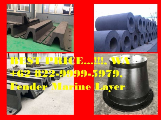
Chat +62 822-9999-5979, Distributor D Fender Rubber Malaysia China Niri Rubber
Chat WA +62 822-9999-5979, Rubber Fender Factory In UAE, Rubber Fender Factory In Kolkata, Rubber Fender Factory In Dammam, Rubber Fender Factory In Bangladesh, Rubber Fender Factory In Sharjah
Indonesian Marine Supplier
Ready for Cylindrical Fender, V Fender (SVF), A-Fender (SAF), M-Fender (SMF), Super Cone Fender (SSCF), Super Cell Fender (SCF), Lambda Fender (LMD), D-Fender
Komplek Jaladha Pura ( AURI )
Jln. Cendrawasih III No. 34
Kel. Margahayu
Bekasi Timur
Bekasi 17113
Klik here => https://wa.me/+6282299995979
Klik here => https://wa.me/+6282299995979
Klik here => https://wa.me/+6282299995979
#rubber fender flares nz#rubber fender guards#fender rubber grommets#rubber welting trim gasket fender flare#gambar rubber fender#rubber fender hs code#rubber fender hardness#rubber fender hs code bangladesh#rubber fender hs code zauba#fender rubber harley#rubber fender pad hs code#hollow rubber fender#harga rubber fender type v#rubber fender indonesia#rubber fender installation#rubber fender image#rubber fender in ship#rubber inner fender material#rubber fender manufacturer in india#rubber fender supplier in philippines
0 notes
Text
2014 Nissan-Datsun Altima Diagrams. DTC # 12-011 Date: 120301
2014 Nissan-Datsun Altima Diagrams. DTC # 12-011 Date: 120301
Campaign PC125 - Brake Master Cylinder
Reference: NTB12-011
Date: March 8, 2012
VOLUNTARY SERVICE CAMPAIGN
2007-2012 ALTIMA SEDAN & COUPE BRAKE MASTER CYLINDER
CAMPAIGN ID #: PC125
APPLIED VEHICLES: 2007-2012 Altima Sedan & Coupe (L32 & CL32)
Check Service COMM to confirm campaign eligibility.
INTRODUCTION
Nissan is conducting a Voluntary Service Campaign on Model Year 2007-2012 Nissan Altima (L32) Sedan and Coupe vehicles to inspect the brake
Systems in vehicles with an illuminated brake warning lamp. Nissan dealers will inspect the brake system and confirm that no brake fluid leak is
present. If no leak is present, the reservoir will be topped off. If a leak in the brake master cylinder is identified, the brake master cylinder will be
replaced.
2019 Nissan-Datsun Altima L4-2.5L (QR25DE) Page 143
The affected vehicles are equipped with a brake warning lamp that will illuminate to alert the driver when fluid in the brake fluid reservoir is low.
Fluid in the reservoir may become low due to normal brake pad wear and not because of any brake system malfunction. While in most instances an
illuminated brake warning lamp is due to normal brake pad wear, a small percentage of vehicles affected by this campaign may have a slow brake
fluid leak at the brake master cylinder.
IDENTIFICATION NUMBER
Nissan has assigned identification number PC125 to this campaign. This number must appear on all communications and documentation of any
nature dealing with this campaign.
DEALER RESPONSIBILITY
Dealers are to repair vehicles falling within range of this campaign that enter the service department. This includes vehicles purchased from private
parties, vehicles presented by transient (tourists) owners, and vehicles in a dealer's inventory.
2019 Nissan-Datsun Altima L4-2.5L (QR25DE) Page 144
Repair Overview
2019 Nissan-Datsun Altima L4-2.5L (QR25DE) Page 145
REQUIRED SPECIAL TOOL J49749
PARTS INFORMATION
2019 Nissan-Datsun Altima L4-2.5L (QR25DE) Page 146
CLAIMS INFORMATION
Service Procedure
NOTE:
Perform this procedure only if the brake warning lamp is ON, or the customer reports the warning lamp was ON in the past.
Brake Master Cylinder Inspection
1. Cover fenders and painted areas to protect them from possible brake fluid splashing.
2019 Nissan-Datsun Altima L4-2.5L (QR25DE) Page 147
2. Locate the brake booster vacuum tube.
3. Carefully pull the vacuum tube from the brake booster (see Figure 2).
4. Remove the rubber grommet from the brake booster (see Figure 2).
IMPORTANT
CAUTION:
If brake fluid is splashed on painted surfaces, immediately wipe off with a clean soft cloth and wash with water.
2019 Nissan-Datsun Altima L4-2.5L (QR25DE) Page 148
5. Connect Special Tool J-49749 as shown in Figure 3. Use shop air supply pressure between 90 and 120 psi.
6. Move/position the suction tube inside the brake booster so that any fluid in the lower area of the brake booster is sucked into the collection
container.
NOTE:
If there is fluid in the lower area of the booster:
^ Keep the collection container upright.
^ If the collection container fills to within 1/2 inch of the top, empty it and then continue.
^ Continue suction until all of the fluid is removed.
7. After you have removed any / all fluid from the brake booster, disconnect the tool and check the collection container.
OK - No fluid in the container:
^ Reinstall all parts removed.
^ Make sure the brake fluid reservoir is full.
^ Check and fill (top-off) under hood fluids (e.g. washer fluid, coolant, brake fluid).
^ Review results of the Multi-Point Inspection with the customer.
2019 Nissan-Datsun Altima L4-2.5L (QR25DE) Page 149
NG - Any amount of fluid in the container:
^ Replace the Brake Master Cylinder - Instructions starting below.
^ Check and fill (top-off) under hood fluids (e.g. washer fluid, coolant, brake fluid).
^ Review results of the Multi-Point Inspection with the customer.
NOTE:
Once fluid is removed from the booster, the booster does not need to be replaced.
IMPORTANT
Brake Master Cylinder Replacement
1. Write down the radio station presets.
2. If equipped, write down the customer settings for the ATC (Automatic Temperature Control) system. (Refer to the Service Manual as needed).
3. Cover fenders and painted areas to protect them from possible brake fluid splashing.
CAUTION:
If brake fluid is splashed on painted surfaces, immediately wipe off with a soft cloth and wash with water.
4. Disconnect the negative battery cable.
5. Disconnect the electrical connector from the Mass Air Flow Sensor.
2019 Nissan-Datsun Altima L4-2.5L (QR25DE) Page 150
6. Remove the items shown in Figure 5 (4 cyl) or Figure 6 (6 cyl).
7. Disconnect the brake fluid level sensor connector.
2019 Nissan-Datsun Altima L4-2.5L (QR25DE) Page 151
8. Disconnect the harness mount from the side of the fluid reservoir.
9. Drain the fluid from the brake master reservoir as follows:
a. Make sure the parking brake is set.
b. Attach a vinyl tube with catch container to a caliper bleed valve.
d. Open the bleed valve.
e. Slowly pump the brake pedal until the brake fluid reservoir is empty.
CAUTION:
^ If equipped with manual transmission, do not push the clutch pedal when the reservoir is empty or you will need to bleed the clutch system.
^ If brake fluid is splashed on painted surfaces, immediately wipe off with a soft cloth and wash with water.
10. If equipped with manual transmission, remove the fluid supply tube for the clutch master cylinder.
CAUTION:
Do Not push the clutch pedal when the reservoir is empty or you will need to bleed the clutch system.
2019 Nissan-Datsun Altima L4-2.5L (QR25DE) Page 152
11. Disconnect the 2 brake lines.
12. Remove the 2 nuts for the brake master cylinder and remove the master cylinder.
NOTE:
Discard old brake master cylinder.
13. Prepare for installation of the new master cylinder:
^ Clean the brake booster in and around the hole for the master cylinder.
^ Make sure the brake master cylinder to booster seal is in place and fully seated as shown.
^ Make sure the primary piston and seal are clean and free of any debris.
CAUTION:
^ Do Not scratch the master cylinder primary piston.
^ Do Not allow the primary piston to contact the brake booster during installation.
2019 Nissan-Datsun Altima L4-2.5L (QR25DE) Page 153
14. Install the brake master cylinder and tighten the nuts.
^ Nut Torque:
15 Nm (1.5 kg-m, 11 ft-lb)
15. Attach the brake lines.
^ Brake line flare nut torque:
18.2 Nm (1.9 kg-m, 13 ft-lb)
16. If equipped with manual transmission, install the fluid supply tube for the clutch master cylinder.
CAUTION:
Do Not push the clutch pedal when the reservoir is empty or you will need to bleed the clutch system.
2019 Nissan-Datsun Altima L4-2.5L (QR25DE) Page 154
17. Re-connect the brake fluid level sensor connector.
18. Re-connect the harness mount to the side of the fluid reservoir.
19. Make sure the rubber grommet and vacuum tube are installed into the brake booster.
20. Re-install the items shown in Figure 5 (4 cyl) or Figure 6 (6 cyl).
21. Re-connect the electrical connector for the Mass Air Flow Sensor.
22. Bleed air from the brake system as follows:
NOTE:
^ Keep brake fluid reservoir filled at least half full while performing the brake bleeding procedure.
^ Use a new fresh sealed bottle of genuine Nissan Super Heavy Duty Brake Fluid (P/N 999MP-A4100P).
2019 Nissan-Datsun Altima L4-2.5L (QR25DE) Page 155
a. Attach a vinyl tube with catch container to the right rear brake caliper or wheel cylinder bleed valve.
b. Fully depress brake pedal 4 to 5 times.
c. With brake pedal depressed, loosen bleed valve to let the air out, and then tighten it immediately.
d. Repeat steps b and c until no more air comes out.
e. Tighten bleed valve. Torque to 8.3 Nm (0.85 kg-m, 73 in-lb).
f. Repeat steps a to e for the other wheels in the following order:
Left Front > Left Rear > Right Front
23. If equipped with manual transmission, make sure the clutch is operating correctly by pumping/cycling the clutch pedal 3 or 4 times.
24. Reset the clock and the radio station presets.
25. If equipped; reset customer's settings for the ATC (Automatic Temperature Control) system. (Refer to the Service Manual as needed.)
26. Initialize auto-up power windows as follows:
a. Turn the ignition ON (keep the transmission in Park and the parking brake applied).
b. Close the door.
C. Operate the power window switch to fully open the window.
d. Pull UP and continue to pull UP on the power window switch to fully close the window.
e. Continue pulling the power window switch UP for 4 seconds after glass stops at fully closed position.
f. Check that auto-up function operates normally.
27. Check and fill (top-off) under hood fluids (e.g. washer fluid, coolant, brake fluid).
28. Review results of the Multi-Point Inspection with the customer.
2019 Nissan-Datsun Altima L4-2.5L (QR25DE) Page 156
from Blogger http://bit.ly/2PschMZ
via IFTTT
0 notes
Text
Why You Still Get Great Value from EPDM Than Other Denver CO Flat Roofing Options
As a commercial property owner, it's important to cut corners where possible without compromising the overall quality of your building. Over-cutting can shorten the lifespan and capability of your Denver CO property, which can possibly leave you with building fines too. However, if you're planning to use EPDM to replace your aging roof, you're not actually cutting down on value. In fact, you're adding more value to your roof.
How is this possible? Everyone knows that EPDM is the cheapest flat roofing material. It only has about 20-25 years lifespan and does not reflect UV Rays as well as TPO or PVC flat roofing material can.
As experienced commercial roofers in Denver CO, we uphold EPDM as an excellent roofing solution. In fact, there are so many good things about it. Thomas.Net has great insight about why EPDM roofs are extremely viable solutions for commercial properties without breaking the bank. Read more below.
EPDM’s biggest advantages lie in how weatherproof it is outdoors. It can resist abrasion, UV rays, ozone, aging, and weather, and it’s the most waterproof rubber available. EPDM is also steam resistant, functioning in up to 392 degrees F (200 C) without air, and chemical resistant, including to polar fluids. With similar properties to silicone rubber below 250 degrees F, EPDM is resilient, has low electrical conductivity, and adheres easily to metals. It’s also very flexible, with 600% elongation and a tensile range of 500-2500 psi, while functioning well in temperatures from -50 degrees F (-45 C) to 350 degrees F (177 C). On top of that, EPDM insulates and reduces noise, part of the reason it’s so commonly used in the automotive industry.
youtube
Further below, it lists the uses EPDM has beyond roofing too.
Automotive
This is EPDM’s most common application, thanks to its flexibility, resiliency, and weatherability. It can be found in vehicle weather stripping, seals, sealant, wire and cable harnesses, and brake systems. It’s also blended with other materials to make fender extensions, rub strips, and car bumpers.
Industrial
Industrial applications use EPDM for its electrically insulating and waterproof properties, as well as its resilience and flexibility. EPDM can be found in parts such as water system O-rings, hoses, and gaskets, as well as in electrical insulators and connectors for wire and cable. It also takes the form of accumulator bladders, diaphragms, grommets, and belts. (Continued)
EPDM does have some disadvantages. One of them is its problematic interaction with different types of solvents such as contact cement, hydrocarbon oils, and lubricants. Therefore, your HVAC maintenance teams must always monitor their use of these substances when servicing your rooftop equipment. In addition, it isn't the best when it comes to preventing fires -- this is important to keep in mind when planning to purchase EPDM roofs.
Lastly, we have found that EPDM quality depends on the manufacturer you source it from. To ensure you get the best EPDM supply and the best EPDM replacement or installation possible, you can always enlist our help at Ropa Roofing. With decades of experience handling exceptional roofing solutions, you're guaranteed only the best results in all your projects. Contact us today!
See More Here: Why You Still Get Great Value from EPDM Than Other Denver CO Flat Roofing Options
Ropa Roofing
795 McIntyre St. Suite 303
Golden, CO 80401
(720)4416331
https://goo.gl/maps/DzC7kmfwj1mf4URo6
0 notes
Text
Parking Sensors
Do you get uneasy while parking? This, however, doesn’t have to be the case. Today, you can execute both reverse and parallel parking with ease with the help of parking sensors. This advanced technology enables you to navigate your vehicle safely without knocking things or people down. Here’s a comprehensive overview of some of the best parking sensors in the market.
Types of Parking Sensors
Parking sensors, also known as proximity sensors are specially designed to let the driver know of the presence of any obstacles as they park. Usually, these sensors are mounted at the vehicle’s rear bumper. Still, they can be mounted on the fenders and front bumper. Here are the different types of parking sensors.
Quick, Easy Tips to Car Scratches
Electromagnetic parking sensors
Electromagnetic parking sensors generate an electromagnetic field across the vehicle to help detect any obstacles within the field. These sensors however only operate when the car is in motion. Many vehicles that come with electromagnetic parking sensors also feature cameras. This means that when your vehicle is in reverse mode, the infotainment screen shows the rear and this helps drivers park their vehicles in reverse with ease.
Is it Legal to Drive After Vaping CBD? Find Out More
Ultrasonic parking sensors
Ultrasonic parking sensors leverage on the sound waves produced from the sensors which beep on detecting obstacles around the vehicle. Usually, the closer you are to the obstacle, the faster and louder the beeping becomes. Sometimes, however, sound waves won’t detect every obstacle. This is why you shouldn’t rely on them solely. Use your mirrors to avoid hitting anything.
Rear-facing cameras
If you can’t seem to get reverse parking right, the rear-facing cameras will come in handy. With these, you can easily park without having to look behind. The good thing about them is that they’ll automatically activate when the vehicle is in reverse mode.
Which are the Best Parking Sensors in the Market today?
Technology is something we can’t while away. The automobile industry, for instance, has been advancing rapidly with players in the industry embracing automation. Advanced accessories such as parking sensors are becoming must-have items in your vehicle. Manufacturers of these advanced technologies are flooding the market which often makes choosing the ideal sensor for your car an arduous task. To ease your search, here are some of the best sensors you’ll find in the market today.
Zone Tech Parking Sensors
Zone tech parking sensors are specially designed to detect any obstacles behind your vehicle. With these sensors, you can easily and safely park your vehicle without hitting on things or even injuring anybody. Zone tech sensors come with a reverse radar system which comes complete with 4 sensors that are fitted on the rear bumper of your car.
It features an advanced chipset and a double CPU to boot coverage and allow precise detection. This gadget comes with an audible sound system which produces a beep sound to alert you if any obstacles are detected. What’s more, the Zone Tech comes with a three-colored (green, yellow, and red) LED display and 7 indicator levels which displays the closeness of obstacles.
Other Features
The manufacturers of the Zone Tech parking lights outdid themselves with this gadget. It’s made of superior quality materials designed to offer excellent durability and performance. All the components have been carefully chosen to avoid overheating especially when the gadget is in operation for prolonged periods.
Further, this parking sensor comes with an adaptive environment technology which means it neither gets too hot or cold during extreme weather conditions. This sensor is easy to assemble and you don’t have to be a professional to assemble it. This gadget is one of the best in the market today. Regardless of the great features, it’s quite affordable which means a big percentage of vehicle owners can afford it without breaking the bank.
Sunvalleytek Car Radar System
The Sunvalley parking sensor is a popularly known reverse radar system. It features excellent features and is made from superior quality materials. This gadget will come in handy to ensure you park your car safely without risking your life and that of your passengers or hitting any obstacle. This sensor comes with 4 ultrasonic sensors which are mounted on your vehicle’s rear bumper. It features an advanced chipset and a double CPU to boost coverage and guarantee better detection during parking.
Colored LED Display
Further, this parking sensor comes with a colored LED display with the colors: red, green, and yellow which come in handy to inform you of your vehicle’s proximity to an obstacle. This car radar system also has a sound system which generates a beeping sound to alert you when it detects obstacles.
How Durable is it?
This parking sensor is specially designed to be shockproof and waterproof too which means they’ll last longer. The radar is made of well-selected superior quality materials to avert overloading and overheating. The installation process is easy and all you need to do is make 4 small holes at the rear bumper where you’ll install the sensors.
Navigate one cable towards the speaker and direct another cable towards the LED display. Apart from the 4 sensors, the package will include a receiver, wires, and a drill bit to facilitate the installation process. Regardless of the difficult to understand instructions on the manual, you’ll find the installation process quite easy.
Pricing
When it comes to the pricing, you’ll be happy to learn that it’s affordable. What’s more, you can return it within thirty days for a refund if you aren’t satisfied.
Hopkins 60100VA nVISION Back up Sensor System
Parking sensors are not only critical for small cars. They come in handy for all vehicles regardless of their makes or models. The Hopkins 60100VA nVISION Back-Up Sensor System is excellently designed to enhance visibility and performance to ensure that you park your car safely.
It comes with ultrasonic sensors fixed at the back bumper as well as an audible alarm which navigates inside the vehicle. The alarm alerts you when you’re approaching an obstacle. It’s designed to start beeping when you’re at approximately 5-feet from the obstacle and becomes faster and louder as you get closer.
The Installation Process
Installing the Hopkins 60100VA nVISION Back-Up Sensor System is a simple process. Rather than drilling holes, this system utilizes two sensors connected on each side of a substitute license bracket plate. All you need is to direct one wire towards the reverse light and another one towards the cabin to connect with the alarm. This sensor system can be connected to any license plate since it features long bolts. It also comes with wire splicing fold-over connectors complete with a rubber grommet which comes in handy to safeguard cables and ease the wiring process.
Pricing
While the Hopkins 60100VA nVISION Back-Up Sensor System is effective, it’s slightly expensive compared to other similar gadgets in the market. Still, if you can afford it, it’s a great option. This sensor system comes with a three-year limited manufacturer’s warranty. Overall, this system if quite good save for the wire that navigates through to the alarm which is quite short meaning it’ll be of no use in some vehicle models.
Esky Car Rear View Reversing Backup Camera
The Esky Car Rear View Reversing Backup Camera is specially designed for you if using a sensor gadget that features a sound system is difficult for you. The camera comes in handy not only to help you park with ease, but it also aids your driving especially because you’re able to view the space you have behind your car.
This gadget captures everything behind your vehicle regardless of the time of day. It comes with 7 infrared LED lights a 135-degree viewing angle, all of which provide you with precise visibility especially in poor lighting conditions. What’s more exciting is the fact that the camera generates superior quality images.
Mounting
One of the best things about this gadget is the fact that you can fix it at your preferred location at the back bumper. However, the manufacturer recommends mounting it on the license plate for a better view. Still, you can adjust the lens if you’re looking for the ultimate rearview clarity.
The installation process will involve connecting the camera’s video output to your car’s display and power cable on your vehicle’s 12V DC power system. This gadget is made using great quality and robust materials but the camera isn’t waterproof which can be disappointing.
Pricing
In terms of pricing, the Esky Car Rear View Reversing Backup Camera is affordable. What’s more, you can still return it within thirty days for a full refund if you aren’t happy with it. What’s more, the camera also comes with a one year manufacturer’s warranty.
Koolertron Car Reverse Parking Sensor System
The Koolertron Car Reverse Parking Sensor System is specially designed to activate once your car is in reverse mode. If there are any obstacles, information is relayed from different sensors to an LED display fixed on the dashboard. The LED comes in different colors which inform you how close to the obstacle you are. This system also features audible beeps which help you figure out how close to the obstacle you are.
Once you place your order, your package should contain a CPU, four sensors, cables, and a display unit. The sensors are omnidirectional to give you great coverage from all the angles. This system is both affordable and functional and will be ideal for you regardless of the make or model of your vehicle.
EKYLIN Car Auto Vehicle Reverse Backup Radar
The EKYLIN Car Auto Vehicle Reverse Backup Radar comes complete with an LED digital screen and a sound system. This brand is popularly known in the market, especially due to the manufacturer’s commitment towards ensuring that the system has state of the art features and excellent performance.
With this gadget, you can easily park in any small spaces. If you’re always struggling with parking, this gadget is specially designed for you. The EKYLIN Car Auto Vehicle Reverse Backup Radar is capable of recognizing every obstacle behind your vehicle up to approximately 8 ft.
Additional Features
This gadget features a double CPU and advanced chipset for precise coverage and detection. It also comes with a three-colored LED digital screen which alerts you when you’re getting closer to an obstacle. You’ll also get an audible sound system which sounds the alarm to let you know that you’re almost hitting an obstacle. You don’t have to be a professional to install this gadget seeing how easy to install it is.
All you need is to drill 4 holes and simply mount the sensors. The only drawback would the short wires which may not reach the front seats. One good thing about this sensor is the fact that it utilizes low power and this is critical when it comes to saving your vehicle battery.
Value
The EKYLIN Car Auto Vehicle Reverse Backup Radar is guaranteed to give you value for your money. Seeing that this gadget is waterproof, you can be sure of its durability. Invest in this sensor and enjoy hassle-free parking.
Frostory Car Reverse Backup Parking Sensor
The Frostory Car Reverse Backup Parking Sensor is a compact gadget that’s specially designed to ease your parking regardless of the time of day. This gadget can recognize obstacles up to 4.9 feet. Of course, some of the similar gadgets in the market has a wider coverage but still, this works well.
The Frostory Car Reverse Backup Parking Sensor features 4 sensitive sensors which mount on your vehicle’s rear bumper, an advanced chip, and a double CPU for enhanced object recognition and coverage. It also comes with an audible sound system which beeps to alert you when you’re closer to an obstacle. The beeping becomes intense with the closer you get to the obstacle to prevent you from causing accidents or damaging your vehicle.
Weather Proof
One good thing about the Frostory Car Reverse Backup Parking Sensor is the fact that it’s weather resistant. It’ll continue functioning amid extreme weather seeing that it has an anti-freeze feature and comes with waterproof details. Generally, this gadget is not only sturdy but it’s also quite durable. You can install it on your own with minimal struggle. All you need to do is drill four holes where you’ll mount your sensors and ensure they’re connected to the speaker. While this gadget comes with a hole saw to facilitate the drilling process, the saw may not be the best quality there is in the market. However, you can still use it if you’ve nothing better.
Pricing
Price is a critical factor to consider when it comes to purchasing anything. the Frostory Car Reverse Backup Parking Sensor has gained popularity among many vehicle owners not only for its unique and excellent features but also for its cost friendliness.
Leshp LED Display Car Vehicle Reverse Backup Radar System
The Leshp LED Display Car Vehicle Reverse Backup Radar System has unique and great features specially designed to guarantee safe parking. This gadget allows vehicle owners to park in restricted spaces with ease while avoiding any obstacles. If you’re among the many people who struggle with reverse parking, this gadget will come in handy to ensure that both you and your passengers are safe.
Ultrasonic Sensors
This gadget comes with 4 ultrasonic sensors which calculate the distance between the obstacle and your vehicle. It also has a colored LED display which comes in handy to let you know how close your car is from the obstacle. The colors are green to show you that you’re within a safe distance, yellow to let you know you’re getting closer, and red to let you know that you’re closer enough to cause an accident and damage your car. This sensor also comes with an upgraded chipset and a double CPU to boost detection and coverage behind your car.
Installation and Durability
The installation process is quite simple and you can do it alone without the help of a professional. All you need is to follow the provided manual and proceed to drill four holes where you’ll fix the sensors. If customer reviews are anything to go by however, some customers reported having difficulties with the wiring. You’ll need sufficient time to read and understand the manual and proceed to execute the installation process like a professional.
This gadget features a unique auto function which activates when the vehicle is ignited and switches off when the engine is shut down. The manufacturers of this gadget outdid themselves with this gadget by making it weatherproof. It can withstand extreme weather conditions and will continue functioning nevertheless.
No Overloading or Overheating
This sensor features protective circuits which ensure prevents it from overloading and overheating. This guarantees your durability and value for your money.
Pricing
The Leshp LED Display Car Vehicle Reverse Backup Radar System is a great product in terms of quality and performance. However, it can be slightly pricey and if you’re looking for a reasonably priced parking sensor, you may be reluctant to choose this one. Still, when you look at the great features of this parking sensor, you can see that the price is worth it.
Finally
Parking sensors are the next big thing in the automobile sector. It’s no doubt that even the most experienced drivers often struggle with parking. This will, however, be a thing of the past with parking sensors which are designed to ease the process.
from Complete Auto Loans https://ift.tt/30aeghB
via IFTTT
0 notes
Text
Installing a New Wiring system on our 1974 Plymouth Duster
Old cars need love. But older cars need new wiring. The simple fact is that while an old car shows its age through tired paint and tread-worn tires, nothing ages worse than your wiring system. In addition to copper wires wearing out and shedding their plastic coverings, the connectors that bring it all together get brittle with time and don’t hold the contacts together properly. Rather than put another bandage on a really sad performing wiring system, we suggest you replace it. American AutoWire wiring loom kits contain everything to make sure your taillights burn bright for many years.
The wiring kit shown here is for the rear section of our 1974 Plymouth Duster. Kits are available for a variety of different vehicle areas including dashboard, engine compartment, and front end wiring system, which includes the headlights. Most of the muscle cars we really love have reached the half-century mark. That means your car’s copper wiring has been heated and cooled a million times making it prone to breaking down creating a short that can be nearly impossible to find.
All that’s required in terms of tools are a set of wire cutters, a sharp wire stripper, and assorted screw drivers for removing stuck taillight plugs, prying open wiring loom clips, and mounting such things on your dome lights. A couple of hours of your time are all it takes to install a new loom to avoid countless hours of not trying to find out why your lights don’t work.
Be sure to note that the most important part of troubleshooting or installing any wiring system is to make sure that all of your grounds are tightly installed and use a star washer where the negative terminals are tightened to the body, frame, or engine. Adding additional grounds with suitably sized cables are strongly encouraged.
So don’t be afraid to tackle your vehicle’s wiring system. With these easy-to-install kits, you only need to take your time and methodically follow the paths of the original wiring system. Obviously, remember to remove both cables from your battery before doing any of this. Staying connected is easier than you thought.
Installing new wiring may not be a sexy upgrade, but will save you lots of time and plenty of frustration in the long term.
American AutoWire’s wiring loom kit for the rear section of our ’74 Plymouth Duster includes not only lots of wire, but the pigtails that attach it to the lighting components, additional plugs, and wiring clips to make for a factory-appearing system.
To make the wiring more manageable, we bound together the wiring loom in this manner with electrical tape.
To protect it from the elements and make it look like a factory installation, we covered the wiring loom, and all exposed wiring, with this flexible covering. This can be ordered separately from American AutoWire.
The main loom clips into the factory harness under the rocker panel in this manner. Note that American AutoWire has maintained the factory style clips configuration so that they plug into an original factory clip, or one of American AutoWire’s replacement clips.
To keep the wiring loom tucked under the rocker, we placed it up against this rail and secured it with the factory fold-down tabs.
Next, we routed the wiring loom into the trunk over the fender well and down inside the crevice on the driver side of the trunk.
With this kit, you can customize your system for your application by trimming down such items as this taillight pigtail lead to fit. Measure twice and cut once was never more appropriate.
With all of our wiring, we made sure to install the supplied end connectors and cover the exposed wiring with our protective covering. With all coverings, we used electrical tape to seal them up.
For this side marker light, we found the proper colored connection wire in the loom through the schematic supplied in the instructions. From there, we clipped the wire to the right length, found the right metal end, and crimped it on the wire. The metal end then clips into the connector and then attaches to the pigtail lead.
The finished lead with the supplied connector looks like this.
We snapped the taillight leads into the housing and measured them to make sure they reached the loom in the right location.
As we did with the side market light, we found the wires for the taillight (remember the backup lighting system and brake lights are also part of this taillight housing) and crimped on the correct metal clips. The supplied wiring schematic is critical here to connect up the right wires.
After inserting the metal end onto the supplied connector, we clipped the two connectors together.
This is what the connections look like when completed — both wires connected and all wiring coverings are included.
As with the driver side, the passenger-side marker light attaches in this manner.
The license plate wiring connector is located in this area. Here you see the raw wires we selected out of the loom before installing the wiring end clips.
The waterproof plug that connects to the license plate light housing features a rubber grommet since it’s exposed to water and other debris.
In keeping with the waterproof theme, this grommet is required to keep the water out of the trunk, but allow the wires to pass through without touching the body metal. We covered the wires, like with all of the exposed wiring, with our protective covering and sealed the ends with electrical tape.
This dome light housing was the original part, but they can be purchased at places like Yearone.com or Classicindustries.com. We pressed the light bulb socket in place and attached the wire from the American AutoWire loom. Once it was in place, we installed the protective covering.
We attached the dome light to the room with the correct screws and taped the wire to the room as well. It was later covered with Dynamat and eventually a headliner.
The wiring loom for the dome light connects to the rest of the loom in the same way as the rest of the connections with metal clips that fit into the supplied connectors.
The final step in the installation is the courtesy light in the rear quarter-panel. It clips in as shown. Again, note that the most important part of troubleshooting or installing any wiring system is to make sure that all of your grounds are tightly installed and use a star washer where the negative terminals are tightened to the body, frame, or engine. Adding additional grounds with suitably sized cables are strongly encouraged, especially when retrofitting so many of today’s add-on electrical products.
The post Installing a New Wiring system on our 1974 Plymouth Duster appeared first on Hot Rod Network.
from Hot Rod Network https://www.hotrod.com/articles/installing-new-wiring-system-1974-plymouth-duster/
via IFTTT
0 notes
Photo


New 2016 Triton Trailers AUT Series AUT1272 Jet Skis For Sale in Oregon,OR
2016 Triton Trailers AUT Series AUT1272, 2016 Triton Trailers AUT Series AUT1272 Triton AUT1272 is an open aluminum deck utility trailer.
Triton's AUT1272 trailers have both extruded aluminum frames and decks with a useable deck size of 12' long by 72" wide. The a-frame tongue, low deck height, and full length 3/8" carriage bolt tiedown channels makes these trailers easy to load, tow, and versatile for all your hauling needs. A good match for low clearance vehicles and other equipment or vehicles.
AUT1272 has a full aluminum ramp which makes for a low angled ramp for easy loading.
AUT1272B trailer is the same trailer but comes standard with a bi-fold ramp. The bi-fold ramp provides a low profile while towing and easily folds out for use.
A wide selection of accessories like side kits, rails kits, stone guards and more will be added soon to make the AUT1272 trailer customizable for hauling ATV's, lawn tractors, bikes, and more.
Features may include:
Aluminum extrusions used throughout the trailer for strength, multiple functionality, and durability
4 D-ring tiedowns in the deck using the 3/8" carriage bolt channels for full adjustment to your loads.
72" wide deck is optimal for UTV use and other side by side machines and haul the gear that also comes along.
Strong A-frame tongue design in frame
Aluminum extruded deck and side rails have integrated 3/8" carriage bolt head channels for adjustment of tiedowns the full length of the deck.
Aluminum decks have a series of full length interlocking aluminum extrusions welded to the frame providing infinite adjustment of tiedowns and durable floor strength.
Aluminum ramp comes with four solid hinges for superior support and strength. Available in a straight and bi-fold style aluminum ramp.
Four cord rubber torsion axles for durability, smooth ride and independent suspension.
Bearing Lube grease system provides grease flow past both bearings for long bearing life and for easy maintenance.
2" Coupler with Safety chains equipped with spring loaded clips and lock pin for added safety when hauling.
LED sealed lights on entire trailer (DOT & Transport Canada compliant)
Molded and protected wire harness for years of worry free use, long life and no splices to fail
Rubber grommeted trailer lights for absorbing light impacts
Sealed lights for long bulb life
3 Year Limited Warranty when warranty registered online. Full warranty details listed under the warranty section. (Non-registered trailers have a one year warranty)
Tongue jack with swivel wheel
Tough molded plastic fenders with frame supported side steps.
Click here to find more detail
0 notes
Text
LIUGONG WHEEL LOADER SPARE PARTS 163
84A0084 V-BELT
84A0221 V-BELT
09C0125 CLAMP
49C9218 HOSE
37B0004 NYLON STRAP
46D2048 PLATE
07A7146 PLATE
58A6571 PLATE
46D2345 PLATE
84A4483 DRAIN PIPE
46C8131 WATER INLET VALVE
20A2473 CLAMP
49C8193 HOSE GP
49C7881 CONDENSER AS
49C7772 FAN
49C7882 CONDENSER
57A0925 SHIM
57A0926 SHIM
57A0927 SHIM
00B0011 BOLT
00B0083 BOLT
41D1191 HANDRAIL
01B1277 BOLT
34C6176 DECORATION
86A3043 PLATFORM
01B1355 BOLT
01B1394 BOLT
72A3514 TOOTH
72A3512 TOOTH
72A3513 TOOTH
32B0077 WORK LIGHT-LH
SP115393 BULB
SP115394 BULB
SP173356 LIGHT BULB
SP173357 LIGHT BULB
34B0118 START SWITCH
SP115882 KIY
97A2253 CUTTING EDGE
96A7566 EDGE-RH
96A7565 EDGE-LH
SP100415 PIPE
09C0235 CLAMP
84A1229 ADHESIVE TAPE
11A0223 PLATE
06B0008 WASHER
01B1370 BOLT
41D1912 STEP
15D1694 FLANGED JOINT
41D1905 STEP
41D1906 STEP
30A8137 HOSE
21C1504X9 HYDRAULIC OIL TANK
41D2348 HANDRAIL
04B0220 SCREW
09C1327 CLAMP
09C1369 CLAMP
82A0092 GASKET
32A2234 SUCTION HOSE
09C1450 CLAMP
12B0447 O-RING
32A2839 SUCTION HOSE
01B1375 BOLT
32A3760 SUCTION HOSE
08D1761 TUBE AS
08D1760 TUBE AS
05B0421 STUD BOLT
08D3165 TUBE AS
00A0034 CONNECTOR
60A0102 PIN
88A1093 SPLIT RING
03C0009 NYLON HOSE
48A4533 PLATE
54C0761 FLEXIBLE SHAFT
19D9859 BRACKET
12B0643 O-RING
12B1710 O-RING
SP202304 SHIFT CONTROL LEVER
SP202303 FLEXIBLE SHAFT L=1500
00A0050 CONNECTOR
06B0668 WASHER
06B0053 WASHER
06B0472 WASHER
20A1854 CLIP
38B0187 HORN
00B0301 BOLT
01D1763 SUPPORT
01D1783 LIGHT BRACKET
84A4829 NYLON STRAP
70C3348 HARNESS
49C7722 FRONT COMBINATION FLOODLIGHT
70C5310 HARNESS
30A4563 DRAIN HOSE
36B0495 CONNECTOR
36B0625 CONNECTOR
84A0317 JACKET
36B1039 CONNECTOR
36B1053 PLUG
36B1070 SOCKET
36B1074 SOCKET
36B1104 SOCKET
83A0136 GROMMET
32B0026 FLOODLIGHT
32B0028 FLOODLIGHT
70C2920 WORK LIGHT HARNESS
70C5919 WORK LIGHT HARNESS
32B0923 WORK LIGHT
03B0287 NUT
19D0979 MOUNTING PLATE
70C4041 CAB HARNESS
34B1225 LIMP MODE SWITCH
SP138311 JOINT
12C6479 SHUTOFF VALVE
13C1647X0 AIR RESERVOIR
79A9305 DECAL
32B0066 DOME LIGHT
SP115400 BULB
49C7749 HOSE
34B1241 PRESSURE SWITCH
SP132005 RHEOSTAT
SP225430 CONDENSER
SP225439 HOUSING
SP225445 FAN
10D9407D1 TUBE AS
40D1201X0D1 REAR FENDER-RH
09D7907D1 TUBE AS
41C0466D1 RIM AS
SP112206 TAPPET
34C5341 SEAT BELT
18C0370 HOSE AS
67A2678 PIPE
82A4839 SPONGE
58A6525 PLATE
20C3640 RADIATOR GP
SP138262 GASKET
SP138319 SEAL
SP225435 A/C HARNESS
SP222921 RELAY
SP221933 THERMOSTAT
SP225431 TEMP SENSOR
SP225432 RELAY
SP225436 EXPANSION VALVE
SP225437 HEATER CORE
SP225438 STRAINER
SP225440 STRAINER
SP225441 SCREW
SP225442 EVAPORATOR CORE
SP225444 BLOWER UNIT
55C4205 EVAPORATOR AS
49C3435 HEATER CORE
55C5188 STRAINER
57A0121 SHIM
57A0122 SHIM
16A6724 BLOCK
15A4852 BLOCK
15A4853 BLOCK
09A0332 BLOCK
17A4242 BLOCK
16A6617 BLOCK
16A6618 BLOCK
16A6619 BLOCK
55A9729 BUSHING
40C7590 HEX SCREW
SP192216 CONTROL VALVE
09C1745 DOUBLE CLAMP
18D8301 BRACKET
11C0045P02 PUMP
SP120113 SEAL KIT
SP100153 RING
12C2051 RELIEF VALVE
12B0021 O-RING
12B0175 O-RING
12B0245 O-RING
12B0342 O-RING
12B0370 O-RING
12B2039 O-RING
05C6661TS HOSE AS
04C1070 HOSE AS
03C0421 HOSE AS
SP192673 SEAL KIT
13C1363X0 AIR RESERVOIR
01B1278 BOLT
08C0485 CABLE
08C0610 CABLE
37B0108 BATTERY
83A0152 RUBBER RING
34B0087 DISCONNECT SWITCH
82A0224 PLATE
00A6917 STUD BOLT
01B1288 BOLT
08C1838 CABLE
07A2412 MOUNTING PLATE
64A2351 FIXED LINK
70C0831 BATTERY CABLE(-)
19D0526 MOUNTING PLATE
12C5180 SAFETY VALVE
05C8172 HOSE AS
66C9451 HOSE AS
32B0078 WORK LIGHT-RH
SP171512 SEAL KIT
46C8428 ELBOW
49C7721 FRONT COMBINATION FLOODLIGHT
SP149738 BULB
SP157772 BULB
SP187006 BULB
86A3091 PLATFORM
02B0147 BOLT
85A5157 INFLATING SCREW
85A5158 INFLATING SCREW
04B0005 SCREW
86A3038 PLATFORM
86A4370 PLATFORM
86A4372 PLATFORM
74A3269 DECAL
60C2023X0 FUEL TANK AS
09C1354 CLAMP
SP135567 PLUG
83A1026 RUBBER RING
20A7707 CLAMP
12B0630 O-RING
30C0273 CONNECTOR
00A1845 CONNECTOR
10A2504 WASHER
12B0842 O-RING
SP202376 SEAL KIT
11C3063 GEAR PUMP
SP174305 SEAL KIT
24C4722 LEVER
SP157364 OUTPUT SHAFT
SP157377 INTERMEDIATE RING
SP186673 THREADED PLUG
SP186689 FLEXIBLE HOSE
24C3526 CONTROL LEVER AS
23C0735 CONTROL LEVER
54C0834 FLEXIBLE SHAFT
54C0871 FLEXIBLE SHAFT
SP202041 CONTROL LEVER
01Y0751X0 FRONT AXLE AS
57A1504 WASHER
57A1503 WASHER
SP166407 ISOLATOR VIBRATION
SP166405 CONNECTOR QCK DISCONNECT
48C6721 ACCUMULATOR BOX
SP204854 FLYWHEEL
03B0677 NUT
12B0646 O-RING
12B0488 O-RING
12C5960 CONTROL VALVE
12B0144 O-RING
12B0299 O-RING
09B0002 RIVET
SP172756 SEAL KIT
12C8534 CONTROL VALVE
SP139502 SUPPORT FAN
04A5488 FLANGE
12C5644 SAFETY VALVE
43D3059 COVER
SP139533 COLLET VALVE
SP192083 SEAL KIT
29A7442 PLATE
06B0800 WASHER
13C1353 ASSISTOR
13C0026 COMBINATION VALVE
SP103818 SEAL KIT
03B0435 NUT
02D9147 MOUNTING PLATE
03B0053 NUT
79A9306 DECAL
37B1704 CONNECTOR
46C0708 WATER RESERVOIR AS
84A3011 WATER HOSE
SP196305 CONDENSER
SP196306 HOUSING
46C8779 VENT
03B0036 NUT
08A0316 PLATE
49C0423 VENT
34C5329 VENT
03B2135 NUT
01B1356 BOLT
01B1357 BOLT
99A4911 PLATE
30A5087 ELBOW
99A4908 PLATE
99A4907 PLATE
99A4969 PLATE
85A5765 AIR DUCT
85A5766 AIR DUCT
85A5769 AIR DUCT
37C1429 AIR DUCT
37C1428 AIR DUCT
85A5770 AIR DUCT
70C1271 HARNESS
91A9505 PLATE
98A7227 PLATE
06B0317 HARD WASHER
13B0353 LIP TYPE SEAL
86A0258 BOOT
60A0014
00B0234 BOLT
53A0012 CAP
16A0012 STOP PLATE
10B0051 GREASE FITTING
00B0013 BOLT
00B0095 BOLT
01B0208 BOLT
06B0015 WASHER
06B0176 WASHER
84A5565 PLUG
79A6819 DECAL
37B0009 CABLE TIE
70C2891 STEERING HARNESS
36B0277 SOCKET
36B0370 PLUG
36B0371 PLUG
36B0647 SOCKET
36B1143 SOCKET
36B1596 SOCKET
36B0009 CONNECTOR
30A0119 HOSE
88A0107 SCREW ROD
16A0072 BLOCK
05B0050 SCREW ROD
12A0149 SUPPORT PLATE
01B0111 BOLT
01D4491 SUPPORT PLATE
01B1283 BOLT
01B1280 BOLT
Read the full article
0 notes
Text
2019 Nissan-Datsun Altima Diagnostic and Repair Information # 12-011 Date: 120301
2019 Nissan-Datsun Altima Diagnostic and Repair Information # 12-011 Date: 120301
Campaign PC125 - Brake Master Cylinder
Reference: NTB12-011
Date: March 8, 2012
VOLUNTARY SERVICE CAMPAIGN
2007-2012 ALTIMA SEDAN & COUPE BRAKE MASTER CYLINDER
CAMPAIGN ID #: PC125
APPLIED VEHICLES: 2007-2012 Altima Sedan & Coupe (L32 & CL32)
Check Service COMM to confirm campaign eligibility.
INTRODUCTION
Nissan is conducting a Voluntary Service Campaign on Model Year 2007-2012 Nissan Altima (L32) Sedan and Coupe vehicles to inspect the brake
Systems in vehicles with an illuminated brake warning lamp. Nissan dealers will inspect the brake system and confirm that no brake fluid leak is
present. If no leak is present, the reservoir will be topped off. If a leak in the brake master cylinder is identified, the brake master cylinder will be
replaced.
2019 Nissan-Datsun Altima L4-2.5L (QR25DE) Page 143
The affected vehicles are equipped with a brake warning lamp that will illuminate to alert the driver when fluid in the brake fluid reservoir is low.
Fluid in the reservoir may become low due to normal brake pad wear and not because of any brake system malfunction. While in most instances an
illuminated brake warning lamp is due to normal brake pad wear, a small percentage of vehicles affected by this campaign may have a slow brake
fluid leak at the brake master cylinder.
IDENTIFICATION NUMBER
Nissan has assigned identification number PC125 to this campaign. This number must appear on all communications and documentation of any
nature dealing with this campaign.
DEALER RESPONSIBILITY
Dealers are to repair vehicles falling within range of this campaign that enter the service department. This includes vehicles purchased from private
parties, vehicles presented by transient (tourists) owners, and vehicles in a dealer's inventory.
2019 Nissan-Datsun Altima L4-2.5L (QR25DE) Page 144
Repair Overview
2019 Nissan-Datsun Altima L4-2.5L (QR25DE) Page 145
REQUIRED SPECIAL TOOL J49749
PARTS INFORMATION
2019 Nissan-Datsun Altima L4-2.5L (QR25DE) Page 146
CLAIMS INFORMATION
Service Procedure
NOTE:
Perform this procedure only if the brake warning lamp is ON, or the customer reports the warning lamp was ON in the past.
Brake Master Cylinder Inspection
1. Cover fenders and painted areas to protect them from possible brake fluid splashing.
2019 Nissan-Datsun Altima L4-2.5L (QR25DE) Page 147
2. Locate the brake booster vacuum tube.
3. Carefully pull the vacuum tube from the brake booster (see Figure 2).
4. Remove the rubber grommet from the brake booster (see Figure 2).
IMPORTANT
CAUTION:
If brake fluid is splashed on painted surfaces, immediately wipe off with a clean soft cloth and wash with water.
2019 Nissan-Datsun Altima L4-2.5L (QR25DE) Page 148
5. Connect Special Tool J-49749 as shown in Figure 3. Use shop air supply pressure between 90 and 120 psi.
6. Move/position the suction tube inside the brake booster so that any fluid in the lower area of the brake booster is sucked into the collection
container.
NOTE:
If there is fluid in the lower area of the booster:
^ Keep the collection container upright.
^ If the collection container fills to within 1/2 inch of the top, empty it and then continue.
^ Continue suction until all of the fluid is removed.
7. After you have removed any / all fluid from the brake booster, disconnect the tool and check the collection container.
OK - No fluid in the container:
^ Reinstall all parts removed.
^ Make sure the brake fluid reservoir is full.
^ Check and fill (top-off) under hood fluids (e.g. washer fluid, coolant, brake fluid).
^ Review results of the Multi-Point Inspection with the customer.
2019 Nissan-Datsun Altima L4-2.5L (QR25DE) Page 149
NG - Any amount of fluid in the container:
^ Replace the Brake Master Cylinder - Instructions starting below.
^ Check and fill (top-off) under hood fluids (e.g. washer fluid, coolant, brake fluid).
^ Review results of the Multi-Point Inspection with the customer.
NOTE:
Once fluid is removed from the booster, the booster does not need to be replaced.
IMPORTANT
Brake Master Cylinder Replacement
1. Write down the radio station presets.
2. If equipped, write down the customer settings for the ATC (Automatic Temperature Control) system. (Refer to the Service Manual as needed).
3. Cover fenders and painted areas to protect them from possible brake fluid splashing.
CAUTION:
If brake fluid is splashed on painted surfaces, immediately wipe off with a soft cloth and wash with water.
4. Disconnect the negative battery cable.
5. Disconnect the electrical connector from the Mass Air Flow Sensor.
2019 Nissan-Datsun Altima L4-2.5L (QR25DE) Page 150
6. Remove the items shown in Figure 5 (4 cyl) or Figure 6 (6 cyl).
7. Disconnect the brake fluid level sensor connector.
2019 Nissan-Datsun Altima L4-2.5L (QR25DE) Page 151
8. Disconnect the harness mount from the side of the fluid reservoir.
9. Drain the fluid from the brake master reservoir as follows:
a. Make sure the parking brake is set.
b. Attach a vinyl tube with catch container to a caliper bleed valve.
d. Open the bleed valve.
e. Slowly pump the brake pedal until the brake fluid reservoir is empty.
CAUTION:
^ If equipped with manual transmission, do not push the clutch pedal when the reservoir is empty or you will need to bleed the clutch system.
^ If brake fluid is splashed on painted surfaces, immediately wipe off with a soft cloth and wash with water.
10. If equipped with manual transmission, remove the fluid supply tube for the clutch master cylinder.
CAUTION:
Do Not push the clutch pedal when the reservoir is empty or you will need to bleed the clutch system.
2019 Nissan-Datsun Altima L4-2.5L (QR25DE) Page 152
11. Disconnect the 2 brake lines.
12. Remove the 2 nuts for the brake master cylinder and remove the master cylinder.
NOTE:
Discard old brake master cylinder.
13. Prepare for installation of the new master cylinder:
^ Clean the brake booster in and around the hole for the master cylinder.
^ Make sure the brake master cylinder to booster seal is in place and fully seated as shown.
^ Make sure the primary piston and seal are clean and free of any debris.
CAUTION:
^ Do Not scratch the master cylinder primary piston.
^ Do Not allow the primary piston to contact the brake booster during installation.
2019 Nissan-Datsun Altima L4-2.5L (QR25DE) Page 153
14. Install the brake master cylinder and tighten the nuts.
^ Nut Torque:
15 Nm (1.5 kg-m, 11 ft-lb)
15. Attach the brake lines.
^ Brake line flare nut torque:
18.2 Nm (1.9 kg-m, 13 ft-lb)
16. If equipped with manual transmission, install the fluid supply tube for the clutch master cylinder.
CAUTION:
Do Not push the clutch pedal when the reservoir is empty or you will need to bleed the clutch system.
2019 Nissan-Datsun Altima L4-2.5L (QR25DE) Page 154
17. Re-connect the brake fluid level sensor connector.
18. Re-connect the harness mount to the side of the fluid reservoir.
19. Make sure the rubber grommet and vacuum tube are installed into the brake booster.
20. Re-install the items shown in Figure 5 (4 cyl) or Figure 6 (6 cyl).
21. Re-connect the electrical connector for the Mass Air Flow Sensor.
22. Bleed air from the brake system as follows:
NOTE:
^ Keep brake fluid reservoir filled at least half full while performing the brake bleeding procedure.
^ Use a new fresh sealed bottle of genuine Nissan Super Heavy Duty Brake Fluid (P/N 999MP-A4100P).
2019 Nissan-Datsun Altima L4-2.5L (QR25DE) Page 155
a. Attach a vinyl tube with catch container to the right rear brake caliper or wheel cylinder bleed valve.
b. Fully depress brake pedal 4 to 5 times.
c. With brake pedal depressed, loosen bleed valve to let the air out, and then tighten it immediately.
d. Repeat steps b and c until no more air comes out.
e. Tighten bleed valve. Torque to 8.3 Nm (0.85 kg-m, 73 in-lb).
f. Repeat steps a to e for the other wheels in the following order:
Left Front > Left Rear > Right Front
23. If equipped with manual transmission, make sure the clutch is operating correctly by pumping/cycling the clutch pedal 3 or 4 times.
24. Reset the clock and the radio station presets.
25. If equipped; reset customer's settings for the ATC (Automatic Temperature Control) system. (Refer to the Service Manual as needed.)
26. Initialize auto-up power windows as follows:
a. Turn the ignition ON (keep the transmission in Park and the parking brake applied).
b. Close the door.
C. Operate the power window switch to fully open the window.
d. Pull UP and continue to pull UP on the power window switch to fully close the window.
e. Continue pulling the power window switch UP for 4 seconds after glass stops at fully closed position.
f. Check that auto-up function operates normally.
27. Check and fill (top-off) under hood fluids (e.g. washer fluid, coolant, brake fluid).
28. Review results of the Multi-Point Inspection with the customer.
2019 Nissan-Datsun Altima L4-2.5L (QR25DE) Page 156
from Blogger http://bit.ly/2XoGsYc
via IFTTT
0 notes
Text
2017 Nissan-Datsun Altima Technical Service Bulletin # 12-011 Date: 120301
2017 Nissan-Datsun Altima Technical Service Bulletin # 12-011 Date: 120301
Campaign PC125 - Brake Master Cylinder
Reference: NTB12-011
Date: March 8, 2012
VOLUNTARY SERVICE CAMPAIGN
2007-2012 ALTIMA SEDAN & COUPE BRAKE MASTER CYLINDER
CAMPAIGN ID #: PC125
APPLIED VEHICLES: 2007-2012 Altima Sedan & Coupe (L32 & CL32)
Check Service COMM to confirm campaign eligibility.
INTRODUCTION
Nissan is conducting a Voluntary Service Campaign on Model Year 2007-2012 Nissan Altima (L32) Sedan and Coupe vehicles to inspect the brake
Systems in vehicles with an illuminated brake warning lamp. Nissan dealers will inspect the brake system and confirm that no brake fluid leak is
present. If no leak is present, the reservoir will be topped off. If a leak in the brake master cylinder is identified, the brake master cylinder will be
replaced.
2017 Nissan-Datsun Altima L4-2.5L (QR25DE) Page 143
The affected vehicles are equipped with a brake warning lamp that will illuminate to alert the driver when fluid in the brake fluid reservoir is low.
Fluid in the reservoir may become low due to normal brake pad wear and not because of any brake system malfunction. While in most instances an
illuminated brake warning lamp is due to normal brake pad wear, a small percentage of vehicles affected by this campaign may have a slow brake
fluid leak at the brake master cylinder.
IDENTIFICATION NUMBER
Nissan has assigned identification number PC125 to this campaign. This number must appear on all communications and documentation of any
nature dealing with this campaign.
DEALER RESPONSIBILITY
Dealers are to repair vehicles falling within range of this campaign that enter the service department. This includes vehicles purchased from private
parties, vehicles presented by transient (tourists) owners, and vehicles in a dealer's inventory.
2017 Nissan-Datsun Altima L4-2.5L (QR25DE) Page 144
Repair Overview
2017 Nissan-Datsun Altima L4-2.5L (QR25DE) Page 145
REQUIRED SPECIAL TOOL J49749
PARTS INFORMATION
2017 Nissan-Datsun Altima L4-2.5L (QR25DE) Page 146
CLAIMS INFORMATION
Service Procedure
NOTE:
Perform this procedure only if the brake warning lamp is ON, or the customer reports the warning lamp was ON in the past.
Brake Master Cylinder Inspection
1. Cover fenders and painted areas to protect them from possible brake fluid splashing.
2017 Nissan-Datsun Altima L4-2.5L (QR25DE) Page 147
2. Locate the brake booster vacuum tube.
3. Carefully pull the vacuum tube from the brake booster (see Figure 2).
4. Remove the rubber grommet from the brake booster (see Figure 2).
IMPORTANT
CAUTION:
If brake fluid is splashed on painted surfaces, immediately wipe off with a clean soft cloth and wash with water.
2017 Nissan-Datsun Altima L4-2.5L (QR25DE) Page 148
5. Connect Special Tool J-49749 as shown in Figure 3. Use shop air supply pressure between 90 and 120 psi.
6. Move/position the suction tube inside the brake booster so that any fluid in the lower area of the brake booster is sucked into the collection
container.
NOTE:
If there is fluid in the lower area of the booster:
^ Keep the collection container upright.
^ If the collection container fills to within 1/2 inch of the top, empty it and then continue.
^ Continue suction until all of the fluid is removed.
7. After you have removed any / all fluid from the brake booster, disconnect the tool and check the collection container.
OK - No fluid in the container:
^ Reinstall all parts removed.
^ Make sure the brake fluid reservoir is full.
^ Check and fill (top-off) under hood fluids (e.g. washer fluid, coolant, brake fluid).
^ Review results of the Multi-Point Inspection with the customer.
2017 Nissan-Datsun Altima L4-2.5L (QR25DE) Page 149
NG - Any amount of fluid in the container:
^ Replace the Brake Master Cylinder - Instructions starting below.
^ Check and fill (top-off) under hood fluids (e.g. washer fluid, coolant, brake fluid).
^ Review results of the Multi-Point Inspection with the customer.
NOTE:
Once fluid is removed from the booster, the booster does not need to be replaced.
IMPORTANT
Brake Master Cylinder Replacement
1. Write down the radio station presets.
2. If equipped, write down the customer settings for the ATC (Automatic Temperature Control) system. (Refer to the Service Manual as needed).
3. Cover fenders and painted areas to protect them from possible brake fluid splashing.
CAUTION:
If brake fluid is splashed on painted surfaces, immediately wipe off with a soft cloth and wash with water.
4. Disconnect the negative battery cable.
5. Disconnect the electrical connector from the Mass Air Flow Sensor.
2017 Nissan-Datsun Altima L4-2.5L (QR25DE) Page 150
6. Remove the items shown in Figure 5 (4 cyl) or Figure 6 (6 cyl).
7. Disconnect the brake fluid level sensor connector.
2017 Nissan-Datsun Altima L4-2.5L (QR25DE) Page 151
8. Disconnect the harness mount from the side of the fluid reservoir.
9. Drain the fluid from the brake master reservoir as follows:
a. Make sure the parking brake is set.
b. Attach a vinyl tube with catch container to a caliper bleed valve.
d. Open the bleed valve.
e. Slowly pump the brake pedal until the brake fluid reservoir is empty.
CAUTION:
^ If equipped with manual transmission, do not push the clutch pedal when the reservoir is empty or you will need to bleed the clutch system.
^ If brake fluid is splashed on painted surfaces, immediately wipe off with a soft cloth and wash with water.
10. If equipped with manual transmission, remove the fluid supply tube for the clutch master cylinder.
CAUTION:
Do Not push the clutch pedal when the reservoir is empty or you will need to bleed the clutch system.
2017 Nissan-Datsun Altima L4-2.5L (QR25DE) Page 152
11. Disconnect the 2 brake lines.
12. Remove the 2 nuts for the brake master cylinder and remove the master cylinder.
NOTE:
Discard old brake master cylinder.
13. Prepare for installation of the new master cylinder:
^ Clean the brake booster in and around the hole for the master cylinder.
^ Make sure the brake master cylinder to booster seal is in place and fully seated as shown.
^ Make sure the primary piston and seal are clean and free of any debris.
CAUTION:
^ Do Not scratch the master cylinder primary piston.
^ Do Not allow the primary piston to contact the brake booster during installation.
2017 Nissan-Datsun Altima L4-2.5L (QR25DE) Page 153
14. Install the brake master cylinder and tighten the nuts.
^ Nut Torque:
15 Nm (1.5 kg-m, 11 ft-lb)
15. Attach the brake lines.
^ Brake line flare nut torque:
18.2 Nm (1.9 kg-m, 13 ft-lb)
16. If equipped with manual transmission, install the fluid supply tube for the clutch master cylinder.
CAUTION:
Do Not push the clutch pedal when the reservoir is empty or you will need to bleed the clutch system.
2017 Nissan-Datsun Altima L4-2.5L (QR25DE) Page 154
17. Re-connect the brake fluid level sensor connector.
18. Re-connect the harness mount to the side of the fluid reservoir.
19. Make sure the rubber grommet and vacuum tube are installed into the brake booster.
20. Re-install the items shown in Figure 5 (4 cyl) or Figure 6 (6 cyl).
21. Re-connect the electrical connector for the Mass Air Flow Sensor.
22. Bleed air from the brake system as follows:
NOTE:
^ Keep brake fluid reservoir filled at least half full while performing the brake bleeding procedure.
^ Use a new fresh sealed bottle of genuine Nissan Super Heavy Duty Brake Fluid (P/N 999MP-A4100P).
2017 Nissan-Datsun Altima L4-2.5L (QR25DE) Page 155
a. Attach a vinyl tube with catch container to the right rear brake caliper or wheel cylinder bleed valve.
b. Fully depress brake pedal 4 to 5 times.
c. With brake pedal depressed, loosen bleed valve to let the air out, and then tighten it immediately.
d. Repeat steps b and c until no more air comes out.
e. Tighten bleed valve. Torque to 8.3 Nm (0.85 kg-m, 73 in-lb).
f. Repeat steps a to e for the other wheels in the following order:
Left Front > Left Rear > Right Front
23. If equipped with manual transmission, make sure the clutch is operating correctly by pumping/cycling the clutch pedal 3 or 4 times.
24. Reset the clock and the radio station presets.
25. If equipped; reset customer's settings for the ATC (Automatic Temperature Control) system. (Refer to the Service Manual as needed.)
26. Initialize auto-up power windows as follows:
a. Turn the ignition ON (keep the transmission in Park and the parking brake applied).
b. Close the door.
C. Operate the power window switch to fully open the window.
d. Pull UP and continue to pull UP on the power window switch to fully close the window.
e. Continue pulling the power window switch UP for 4 seconds after glass stops at fully closed position.
f. Check that auto-up function operates normally.
27. Check and fill (top-off) under hood fluids (e.g. washer fluid, coolant, brake fluid).
28. Review results of the Multi-Point Inspection with the customer.
2017 Nissan-Datsun Altima L4-2.5L (QR25DE) Page 156
from Blogger https://ift.tt/2Fu213E
via IFTTT
0 notes
Text
Campaign PC125 - Brake Master Cylinder
2010 Nissan-Datsun Altima L4-2.5L (QR25DE) Hybrid Technical Service Bulletin # 12-011 Date: 120301
Campaign PC125 - Brake Master Cylinder
Reference: NTB12-011
Date: March 8, 2012
VOLUNTARY SERVICE CAMPAIGN
2007-2012 ALTIMA SEDAN & COUPE BRAKE MASTER CYLINDER
CAMPAIGN ID #: PC125
APPLIED VEHICLES: 2007-2012 Altima Sedan & Coupe (L32 & CL32)
Check Service COMM to confirm campaign eligibility.
INTRODUCTION
Nissan is conducting a Voluntary Service Campaign on Model Year 2007-2012 Nissan Altima (L32) Sedan and Coupe vehicles to inspect the brake
Systems in vehicles with an illuminated brake warning lamp. Nissan dealers will inspect the brake system and confirm that no brake fluid leak is
present. If no leak is present, the reservoir will be topped off. If a leak in the brake master cylinder is identified, the brake master cylinder will be
replaced.
2010 Nissan-Datsun Altima L4-2.5L (QR25DE) Hybrid Page 119
The affected vehicles are equipped with a brake warning lamp that will illuminate to alert the driver when fluid in the brake fluid reservoir is low.
Fluid in the reservoir may become low due to normal brake pad wear and not because of any brake system malfunction. While in most instances an
illuminated brake warning lamp is due to normal brake pad wear, a small percentage of vehicles affected by this campaign may have a slow brake
fluid leak at the brake master cylinder.
IDENTIFICATION NUMBER
Nissan has assigned identification number PC125 to this campaign. This number must appear on all communications and documentation of any
nature dealing with this campaign.
DEALER RESPONSIBILITY
Dealers are to repair vehicles falling within range of this campaign that enter the service department. This includes vehicles purchased from private
parties, vehicles presented by transient (tourists) owners, and vehicles in a dealer's inventory.
2010 Nissan-Datsun Altima L4-2.5L (QR25DE) Hybrid Page 120
Repair Overview
2010 Nissan-Datsun Altima L4-2.5L (QR25DE) Hybrid Page 121
REQUIRED SPECIAL TOOL J49749
PARTS INFORMATION
2010 Nissan-Datsun Altima L4-2.5L (QR25DE) Hybrid Page 122
CLAIMS INFORMATION
Service Procedure
NOTE:
Perform this procedure only if the brake warning lamp is ON, or the customer reports the warning lamp was ON in the past.
Brake Master Cylinder Inspection
1. Cover fenders and painted areas to protect them from possible brake fluid splashing.
2010 Nissan-Datsun Altima L4-2.5L (QR25DE) Hybrid Page 123
2. Locate the brake booster vacuum tube.
3. Carefully pull the vacuum tube from the brake booster (see Figure 2).
4. Remove the rubber grommet from the brake booster (see Figure 2).
IMPORTANT
CAUTION:
If brake fluid is splashed on painted surfaces, immediately wipe off with a clean soft cloth and wash with water.
2010 Nissan-Datsun Altima L4-2.5L (QR25DE) Hybrid Page 124
5. Connect Special Tool J-49749 as shown in Figure 3. Use shop air supply pressure between 90 and 120 psi.
6. Move/position the suction tube inside the brake booster so that any fluid in the lower area of the brake booster is sucked into the collection
container.
NOTE:
If there is fluid in the lower area of the booster:
^ Keep the collection container upright.
^ If the collection container fills to within 1/2 inch of the top, empty it and then continue.
^ Continue suction until all of the fluid is removed.
7. After you have removed any / all fluid from the brake booster, disconnect the tool and check the collection container.
OK - No fluid in the container:
^ Reinstall all parts removed.
^ Make sure the brake fluid reservoir is full.
^ Check and fill (top-off) under hood fluids (e.g. washer fluid, coolant, brake fluid).
^ Review results of the Multi-Point Inspection with the customer.
2010 Nissan-Datsun Altima L4-2.5L (QR25DE) Hybrid Page 125
NG - Any amount of fluid in the container:
^ Replace the Brake Master Cylinder - Instructions starting below.
^ Check and fill (top-off) under hood fluids (e.g. washer fluid, coolant, brake fluid).
^ Review results of the Multi-Point Inspection with the customer.
NOTE:
Once fluid is removed from the booster, the booster does not need to be replaced.
IMPORTANT
Brake Master Cylinder Replacement
1. Write down the radio station presets.
2. If equipped, write down the customer settings for the ATC (Automatic Temperature Control) system. (Refer to the Service Manual as needed).
3. Cover fenders and painted areas to protect them from possible brake fluid splashing.
CAUTION:
If brake fluid is splashed on painted surfaces, immediately wipe off with a soft cloth and wash with water.
4. Disconnect the negative battery cable.
5. Disconnect the electrical connector from the Mass Air Flow Sensor.
2010 Nissan-Datsun Altima L4-2.5L (QR25DE) Hybrid Page 126
6. Remove the items shown in Figure 5 (4 cyl) or Figure 6 (6 cyl).
7. Disconnect the brake fluid level sensor connector.
2010 Nissan-Datsun Altima L4-2.5L (QR25DE) Hybrid Page 127
8. Disconnect the harness mount from the side of the fluid reservoir.
9. Drain the fluid from the brake master reservoir as follows:
a. Make sure the parking brake is set.
b. Attach a vinyl tube with catch container to a caliper bleed valve.
d. Open the bleed valve.
e. Slowly pump the brake pedal until the brake fluid reservoir is empty.
CAUTION:
^ If equipped with manual transmission, do not push the clutch pedal when the reservoir is empty or you will need to bleed the clutch system.
^ If brake fluid is splashed on painted surfaces, immediately wipe off with a soft cloth and wash with water.
10. If equipped with manual transmission, remove the fluid supply tube for the clutch master cylinder.
CAUTION:
Do Not push the clutch pedal when the reservoir is empty or you will need to bleed the clutch system.
2010 Nissan-Datsun Altima L4-2.5L (QR25DE) Hybrid Page 128
11. Disconnect the 2 brake lines.
12. Remove the 2 nuts for the brake master cylinder and remove the master cylinder.
NOTE:
Discard old brake master cylinder.
13. Prepare for installation of the new master cylinder:
^ Clean the brake booster in and around the hole for the master cylinder.
^ Make sure the brake master cylinder to booster seal is in place and fully seated as shown.
^ Make sure the primary piston and seal are clean and free of any debris.
CAUTION:
^ Do Not scratch the master cylinder primary piston.
^ Do Not allow the primary piston to contact the brake booster during installation.
2010 Nissan-Datsun Altima L4-2.5L (QR25DE) Hybrid Page 129
14. Install the brake master cylinder and tighten the nuts.
^ Nut Torque:
15 Nm (1.5 kg-m, 11 ft-lb)
15. Attach the brake lines.
^ Brake line flare nut torque:
18.2 Nm (1.9 kg-m, 13 ft-lb)
16. If equipped with manual transmission, install the fluid supply tube for the clutch master cylinder.
CAUTION:
Do Not push the clutch pedal when the reservoir is empty or you will need to bleed the clutch system.
2010 Nissan-Datsun Altima L4-2.5L (QR25DE) Hybrid Page 130
17. Re-connect the brake fluid level sensor connector.
18. Re-connect the harness mount to the side of the fluid reservoir.
19. Make sure the rubber grommet and vacuum tube are installed into the brake booster.
20. Re-install the items shown in Figure 5 (4 cyl) or Figure 6 (6 cyl).
21. Re-connect the electrical connector for the Mass Air Flow Sensor.
22. Bleed air from the brake system as follows:
NOTE:
^ Keep brake fluid reservoir filled at least half full while performing the brake bleeding procedure.
^ Use a new fresh sealed bottle of genuine Nissan Super Heavy Duty Brake Fluid (P/N 999MP-A4100P).
2010 Nissan-Datsun Altima L4-2.5L (QR25DE) Hybrid Page 131
a. Attach a vinyl tube with catch container to the right rear brake caliper or wheel cylinder bleed valve.
b. Fully depress brake pedal 4 to 5 times.
c. With brake pedal depressed, loosen bleed valve to let the air out, and then tighten it immediately.
d. Repeat steps b and c until no more air comes out.
e. Tighten bleed valve. Torque to 8.3 Nm (0.85 kg-m, 73 in-lb).
f. Repeat steps a to e for the other wheels in the following order:
Left Front > Left Rear > Right Front
23. If equipped with manual transmission, make sure the clutch is operating correctly by pumping/cycling the clutch pedal 3 or 4 times.
24. Reset the clock and the radio station presets.
25. If equipped; reset customer's settings for the ATC (Automatic Temperature Control) system. (Refer to the Service Manual as needed.)
26. Initialize auto-up power windows as follows:
a. Turn the ignition ON (keep the transmission in Park and the parking brake applied).
b. Close the door.
C. Operate the power window switch to fully open the window.
d. Pull UP and continue to pull UP on the power window switch to fully close the window.
e. Continue pulling the power window switch UP for 4 seconds after glass stops at fully closed position.
f. Check that auto-up function operates normally.
27. Check and fill (top-off) under hood fluids (e.g. washer fluid, coolant, brake fluid).
28. Review results of the Multi-Point Inspection with the customer.
2010 Nissan-Datsun Altima L4-2.5L (QR25DE) Hybrid Page 132
from Blogger https://ift.tt/2NsstNq
via IFTTT
0 notes
Text
Campaign PC125 - Brake Master Cylinder
2010 Nissan-Datsun Altima L4-2.5L (QR25DE) Technical Service Bulletin # 12-011 Date: 120301
Campaign PC125 - Brake Master Cylinder
Reference: NTB12-011
Date: March 8, 2012
VOLUNTARY SERVICE CAMPAIGN
2007-2012 ALTIMA SEDAN & COUPE BRAKE MASTER CYLINDER
CAMPAIGN ID #: PC125
APPLIED VEHICLES: 2007-2012 Altima Sedan & Coupe (L32 & CL32)
Check Service COMM to confirm campaign eligibility.
INTRODUCTION
Nissan is conducting a Voluntary Service Campaign on Model Year 2007-2012 Nissan Altima (L32) Sedan and Coupe vehicles to inspect the brake
Systems in vehicles with an illuminated brake warning lamp. Nissan dealers will inspect the brake system and confirm that no brake fluid leak is
present. If no leak is present, the reservoir will be topped off. If a leak in the brake master cylinder is identified, the brake master cylinder will be
replaced.
2010 Nissan-Datsun Altima L4-2.5L (QR25DE) Page 143
The affected vehicles are equipped with a brake warning lamp that will illuminate to alert the driver when fluid in the brake fluid reservoir is low.
Fluid in the reservoir may become low due to normal brake pad wear and not because of any brake system malfunction. While in most instances an
illuminated brake warning lamp is due to normal brake pad wear, a small percentage of vehicles affected by this campaign may have a slow brake
fluid leak at the brake master cylinder.
IDENTIFICATION NUMBER
Nissan has assigned identification number PC125 to this campaign. This number must appear on all communications and documentation of any
nature dealing with this campaign.
DEALER RESPONSIBILITY
Dealers are to repair vehicles falling within range of this campaign that enter the service department. This includes vehicles purchased from private
parties, vehicles presented by transient (tourists) owners, and vehicles in a dealer's inventory.
2010 Nissan-Datsun Altima L4-2.5L (QR25DE) Page 144
Repair Overview
2010 Nissan-Datsun Altima L4-2.5L (QR25DE) Page 145
REQUIRED SPECIAL TOOL J49749
PARTS INFORMATION
2010 Nissan-Datsun Altima L4-2.5L (QR25DE) Page 146
CLAIMS INFORMATION
Service Procedure
NOTE:
Perform this procedure only if the brake warning lamp is ON, or the customer reports the warning lamp was ON in the past.
Brake Master Cylinder Inspection
1. Cover fenders and painted areas to protect them from possible brake fluid splashing.
2010 Nissan-Datsun Altima L4-2.5L (QR25DE) Page 147
2. Locate the brake booster vacuum tube.
3. Carefully pull the vacuum tube from the brake booster (see Figure 2).
4. Remove the rubber grommet from the brake booster (see Figure 2).
IMPORTANT
CAUTION:
If brake fluid is splashed on painted surfaces, immediately wipe off with a clean soft cloth and wash with water.
2010 Nissan-Datsun Altima L4-2.5L (QR25DE) Page 148
5. Connect Special Tool J-49749 as shown in Figure 3. Use shop air supply pressure between 90 and 120 psi.
6. Move/position the suction tube inside the brake booster so that any fluid in the lower area of the brake booster is sucked into the collection
container.
NOTE:
If there is fluid in the lower area of the booster:
^ Keep the collection container upright.
^ If the collection container fills to within 1/2 inch of the top, empty it and then continue.
^ Continue suction until all of the fluid is removed.
7. After you have removed any / all fluid from the brake booster, disconnect the tool and check the collection container.
OK - No fluid in the container:
^ Reinstall all parts removed.
^ Make sure the brake fluid reservoir is full.
^ Check and fill (top-off) under hood fluids (e.g. washer fluid, coolant, brake fluid).
^ Review results of the Multi-Point Inspection with the customer.
2010 Nissan-Datsun Altima L4-2.5L (QR25DE) Page 149
NG - Any amount of fluid in the container:
^ Replace the Brake Master Cylinder - Instructions starting below.
^ Check and fill (top-off) under hood fluids (e.g. washer fluid, coolant, brake fluid).
^ Review results of the Multi-Point Inspection with the customer.
NOTE:
Once fluid is removed from the booster, the booster does not need to be replaced.
IMPORTANT
Brake Master Cylinder Replacement
1. Write down the radio station presets.
2. If equipped, write down the customer settings for the ATC (Automatic Temperature Control) system. (Refer to the Service Manual as needed).
3. Cover fenders and painted areas to protect them from possible brake fluid splashing.
CAUTION:
If brake fluid is splashed on painted surfaces, immediately wipe off with a soft cloth and wash with water.
4. Disconnect the negative battery cable.
5. Disconnect the electrical connector from the Mass Air Flow Sensor.
2010 Nissan-Datsun Altima L4-2.5L (QR25DE) Page 150
6. Remove the items shown in Figure 5 (4 cyl) or Figure 6 (6 cyl).
7. Disconnect the brake fluid level sensor connector.
2010 Nissan-Datsun Altima L4-2.5L (QR25DE) Page 151
8. Disconnect the harness mount from the side of the fluid reservoir.
9. Drain the fluid from the brake master reservoir as follows:
a. Make sure the parking brake is set.
b. Attach a vinyl tube with catch container to a caliper bleed valve.
d. Open the bleed valve.
e. Slowly pump the brake pedal until the brake fluid reservoir is empty.
CAUTION:
^ If equipped with manual transmission, do not push the clutch pedal when the reservoir is empty or you will need to bleed the clutch system.
^ If brake fluid is splashed on painted surfaces, immediately wipe off with a soft cloth and wash with water.
10. If equipped with manual transmission, remove the fluid supply tube for the clutch master cylinder.
CAUTION:
Do Not push the clutch pedal when the reservoir is empty or you will need to bleed the clutch system.
2010 Nissan-Datsun Altima L4-2.5L (QR25DE) Page 152
11. Disconnect the 2 brake lines.
12. Remove the 2 nuts for the brake master cylinder and remove the master cylinder.
NOTE:
Discard old brake master cylinder.
13. Prepare for installation of the new master cylinder:
^ Clean the brake booster in and around the hole for the master cylinder.
^ Make sure the brake master cylinder to booster seal is in place and fully seated as shown.
^ Make sure the primary piston and seal are clean and free of any debris.
CAUTION:
^ Do Not scratch the master cylinder primary piston.
^ Do Not allow the primary piston to contact the brake booster during installation.
2010 Nissan-Datsun Altima L4-2.5L (QR25DE) Page 153
14. Install the brake master cylinder and tighten the nuts.
^ Nut Torque:
15 Nm (1.5 kg-m, 11 ft-lb)
15. Attach the brake lines.
^ Brake line flare nut torque:
18.2 Nm (1.9 kg-m, 13 ft-lb)
16. If equipped with manual transmission, install the fluid supply tube for the clutch master cylinder.
CAUTION:
Do Not push the clutch pedal when the reservoir is empty or you will need to bleed the clutch system.
2010 Nissan-Datsun Altima L4-2.5L (QR25DE) Page 154
17. Re-connect the brake fluid level sensor connector.
18. Re-connect the harness mount to the side of the fluid reservoir.
19. Make sure the rubber grommet and vacuum tube are installed into the brake booster.
20. Re-install the items shown in Figure 5 (4 cyl) or Figure 6 (6 cyl).
21. Re-connect the electrical connector for the Mass Air Flow Sensor.
22. Bleed air from the brake system as follows:
NOTE:
^ Keep brake fluid reservoir filled at least half full while performing the brake bleeding procedure.
^ Use a new fresh sealed bottle of genuine Nissan Super Heavy Duty Brake Fluid (P/N 999MP-A4100P).
2010 Nissan-Datsun Altima L4-2.5L (QR25DE) Page 155
a. Attach a vinyl tube with catch container to the right rear brake caliper or wheel cylinder bleed valve.
b. Fully depress brake pedal 4 to 5 times.
c. With brake pedal depressed, loosen bleed valve to let the air out, and then tighten it immediately.
d. Repeat steps b and c until no more air comes out.
e. Tighten bleed valve. Torque to 8.3 Nm (0.85 kg-m, 73 in-lb).
f. Repeat steps a to e for the other wheels in the following order:
Left Front > Left Rear > Right Front
23. If equipped with manual transmission, make sure the clutch is operating correctly by pumping/cycling the clutch pedal 3 or 4 times.
24. Reset the clock and the radio station presets.
25. If equipped; reset customer's settings for the ATC (Automatic Temperature Control) system. (Refer to the Service Manual as needed.)
26. Initialize auto-up power windows as follows:
a. Turn the ignition ON (keep the transmission in Park and the parking brake applied).
b. Close the door.
C. Operate the power window switch to fully open the window.
d. Pull UP and continue to pull UP on the power window switch to fully close the window.
e. Continue pulling the power window switch UP for 4 seconds after glass stops at fully closed position.
f. Check that auto-up function operates normally.
27. Check and fill (top-off) under hood fluids (e.g. washer fluid, coolant, brake fluid).
28. Review results of the Multi-Point Inspection with the customer.
2010 Nissan-Datsun Altima L4-2.5L (QR25DE) Page 156
from Blogger http://bit.ly/2CNwYx9
via IFTTT
0 notes
Text
Campaign PC125 - Brake Master Cylinder Replacement
Disclaimer2010 Nissan-Datsun Altima L4-2.5L (QR25DE) Technical Service Bulletin # 12-011C Date: 130307
Campaign PC125 - Brake Master Cylinder Replacement
Reference: NTB12-011C
Date: MARCH 7, 2013
VOLUNTARY SERVICE CAMPAIGN
2007-2012 ALTIMA SEDAN & COUPE BRAKE MASTER CYLINDER
This bulletin has been amended. "This Voluntary Service Campaign DOES NOT APPLY to Altima Hybrid (L32H) vehicles" was added to the
Applied Vehicles section. Please discard previous versions.
CAMPAIGN ID #: PC125
APPLIED VEHICLES: 2007 - 2012 Altima Sedan & Coupe (L32 & CL32)
2010 Nissan-Datsun Altima L4-2.5L (QR25DE) Page 492
>> This Voluntary Service Campaign DOES NOT APPLY to Altima Hybrid (L32H) vehicles
Refer to the flow chart (Repair Overview) for campaign eligibility.
INTRODUCTION
Nissan is conducting a Voluntary Service Campaign on Model Year 2007-2012 Nissan Altima (L32) Sedan and Coupe vehicles to inspect the brake
system in vehicles with an illuminated brake warning lamp. Nissan dealers will inspect the brake system and confirm that no brake fluid leak is
present. If no leak is present, the reservoir will be topped off. If a leak in the brake master cylinder is identified, the brake master cylinder will be
replaced.
The affected vehicles are equipped with a brake warning lamp that will illuminate to alert the driver when fluid in the brake fluid reservoir is low.
Fluid in the reservoir may become low due to normal brake pad wear and not because of any brake system malfunction. While in most instances an
illuminated brake warning lamp is due to normal brake pad wear, a small percentage of vehicles affected by this campaign may have a slow brake
fluid leak at the brake master cylinder.
IDENTIFICATION NUMBER
Nissan has assigned identification number PC125 to this campaign. This number must appear on all communications and documentation of any
nature dealing with this campaign.
DEALER RESPONSIBILITY
This action is only required if the brake warning lamp is currently illuminated, or the customer states it was recently illuminated while driving. In
addition, this campaign is intended to promote customer satisfaction. This inspection may also be performed based on customer request, regardless
of the warning lamp illumination.
2010 Nissan-Datsun Altima L4-2.5L (QR25DE) Page 493
Repair Overview
2010 Nissan-Datsun Altima L4-2.5L (QR25DE) Page 494
REQUIRED SPECIAL TOOL J-49749
PARTS INFORMATION
2010 Nissan-Datsun Altima L4-2.5L (QR25DE) Page 495
CLAIMS INFORMATION
Disclaimer
Service Procedure
NOTE:
Perform this procedure only if the brake warning lamp is ON, or the customer reports the warning lamp was ON in the past.
Brake Master Cylinder Inspection
1. Cover fenders and painted areas to protect them from possible brake fluid splashing.
2010 Nissan-Datsun Altima L4-2.5L (QR25DE) Page 496
2. Locate the brake booster vacuum tube.
3. Carefully pull the vacuum tube from the brake booster (see Figure 2).
4. Remove the rubber grommet from the brake booster (see Figure 2).
IMPORTANT
CAUTION:
If brake fluid is splashed on painted surfaces, immediately wipe off with a clean soft cloth and wash with water.
2010 Nissan-Datsun Altima L4-2.5L (QR25DE) Page 497
5. Connect Special Tool J-49749 as shown in Figure 3.
^ Use shop air supply pressure between 90 and 120 psi.
6. Move/position the suction tube inside the brake booster so that any fluid in the lower area of the brake booster is sucked into the collection
container.
NOTE:
If there is fluid in the lower area of the booster:
^ Keep the collection container upright.
^ If the collection container fills to within 1/2 inch of the top, empty it and then continue.
^ Continue suction until all of the fluid is removed.
7. After you have removed any / all fluid from the brake booster, disconnect the tool and check the collection container.
OK - No fluid in the container:
^ Reinstall all parts removed.
^ Make sure the brake fluid reservoir is full.
^ Check and fill (top-off) under hood fluids (e.g. washer fluid, coolant, brake fluid).
^ Review results of the Multi-Point Inspection with the customer.
NG - Any amount of fluid in the container:
2010 Nissan-Datsun Altima L4-2.5L (QR25DE) Page 498
^ Replace the Brake Master Cylinder - Instructions below.
^ Check and fill (top-off) under hood fluids (e.g. washer fluid, coolant, brake fluid).
^ Review results of the Multi-Point Inspection with the customer.
NOTE:
Once fluid is removed from the booster, the booster does not need to be replaced.
IMPORTANT
Brake Master Cylinder Replacement
1. Write down the radio station presets.
2. If equipped, write down the customer settings for the ATC (Automatic Temperature Control) system. (Refer to the Service Manual as needed).
3. Cover fenders and painted areas to protect them from possible brake fluid splashing.
CAUTION:
If brake fluid is splashed on painted surfaces, immediately wipe off with a soft cloth and wash with water.
4. Disconnect the negative battery cable.
5. Disconnect the electrical connector from the Mass Air Flow Sensor.
2010 Nissan-Datsun Altima L4-2.5L (QR25DE) Page 499
6. Remove the items shown in Figure 5 (4 cyl) or Figure 6 (6 cyl).
7. Disconnect the brake fluid level sensor connector.
2010 Nissan-Datsun Altima L4-2.5L (QR25DE) Page 500
8. Disconnect the harness mount from the side of the fluid reservoir.
9. Drain the fluid from the brake master reservoir as follows:
a Make sure the parking brake is set.
b. Attach a vinyl tube with catch container to a caliper bleed valve.
d. Open the bleed valve.
e. Slowly pump the brake pedal until the brake fluid reservoir is empty.
CAUTION:
^ If equipped with manual transmission, do not push the clutch pedal when the reservoir is empty or you will need to bleed the clutch
system.
^ If brake fluid is splashed on painted surfaces, immediately wipe off with a soft cloth and wash with water.
10. If equipped with manual transmission, remove the fluid supply tube for the clutch master cylinder.
CAUTION:
Do Not push the clutch pedal when the reservoir is empty or you will need to bleed the clutch system.
2010 Nissan-Datsun Altima L4-2.5L (QR25DE) Page 501
11. Disconnect the 2 brake lines.
12. Remove the 2 attachment nuts for the brake master cylinder and then remove the brake master cylinder.
NOTE:
Do not reuse the old brake master cylinder.
13. Prepare for installation of the new master cylinder:
^ Clean the brake booster in and around the hole for the master cylinder.
^ Make sure the brake master cylinder to booster seal is in place and fully seated as shown.
^ Make sure the primary piston and seal are clean and free of any debris.
CAUTION:
^ Do Not scratch the master cylinder primary piston.
^ Do Not allow the primary piston to contact the brake booster during installation.
2010 Nissan-Datsun Altima L4-2.5L (QR25DE) Page 502
14. Install the brake master cylinder and tighten the nuts.
^ Nut Torque:
15 N-m (1.5 kg-m, 11 ft-lb)
15. Attach the brake lines.
^ Brake line flare nut torque:
18.2 N-m (1.9 kg-m, 13 ft-lb)
16. If equipped with manual transmission, install the fluid supply tube for the clutch master cylinder.
CAUTION:
Do Not push the clutch pedal when the reservoir is empty or you will need to bleed the clutch system.
17. Re-connect the brake fluid level sensor connector.
2010 Nissan-Datsun Altima L4-2.5L (QR25DE) Page 503
18. Re-connect the harness mount to the side of the fluid reservoir.
19. Make sure the rubber grommet and vacuum tube are installed into the brake booster.
20. Re-install the items shown in Figure 5 (4 cyl) or Figure 6 (6 cyl).
21. Re-connect the electrical connector for the Mass Air Flow Sensor.
22. Bleed air from the brake system as follows:
NOTE:
^ Keep brake fluid reservoir filled at least half full while performing the brake bleeding procedure.
^ Use a new fresh sealed bottle of genuine Nissan Super Heavy Duty Brake Fluid (P/N 999MP-A4100P).
2010 Nissan-Datsun Altima L4-2.5L (QR25DE) Page 504
a. Attach a vinyl tube with catch container to the right rear brake caliper or wheel cylinder bleed valve.
b. Fully depress brake pedal 4 to 5 times.
c. With brake pedal depressed, loosen bleed valve to let the air out, and then tighten it immediately.
d. Repeat steps b and c until no more air comes out.
e. Tighten bleed valve. Torque to 8.3 N-m (0.85 kg-m, 73 in-lb).
f. Repeat steps a to e for the other wheels in the following order:
Left Front > Left Rear > Right Front
23. If equipped with manual transmission, make sure the clutch is operating correctly by pumping/cycling the clutch pedal 3 or 4 times.
24. Reset the clock and the radio station presets.
25. If equipped; reset customers settings for the ATC (Automatic Temperature Control) system. (Refer to the Service Manual as needed.)
26. Initialize auto-up power windows as follows:
a. Turn the ignition ON (keep the transmission in Park and the parking brake applied).
b. Close the door.
c. Operate the power window switch to fully open the window.
d. Pull UP and continue to pull UP on the power window switch to fully close the window.
e. Continue pulling the power window switch UP for 4 seconds after glass stops at fully closed position.
f. Check that auto-up function operates normally.
27. Check and fill (top-off) under hood fluids (e.g. washer fluid, coolant, brake fluid).
28. Review results of the Multi-Point Inspection with the customer.
2010 Nissan-Datsun Altima L4-2.5L (QR25DE) Page 505
from Blogger http://bit.ly/2RDo5Ay
via IFTTT
0 notes
Text
Replacing a C3 Corvette Evaporator
Both evaporators and heater cores have a dramatic affect on the comfort level inside a Corvette. Another thing they have in common is that their replacement is a job many owners dread. Fortunately, each can be replaced separately at different times because there is very little labor overlap for these procedures in a C3. Part 1 showed heater core replacement and restoring the effective operation of the heater box and ducts. Part 2 details the replacement of the evaporator, which some Corvette owners—particularly those of us in southern states—may argue is more important than the heater core.
Replacing the evaporator can be easier than replacing the heater core on many C3s. Disconnecting the VIR (Valves-In-Receiver assembly), which was used from 1973-’77 (early), can be the toughest part of the job. But even then, take some consolation that this job is much easier than on many late-model cars and trucks. As an example, some European luxury cars require four full days of shop labor to replace their evaporators.
If your car has a VIR, one modification that makes this job so much easier is to install a VIR replacement kit. Your C3’s air conditioning is then converted to an orifice tube system like most modern A/C systems. An orifice tube system is much simpler and easier to work on. Plus, an orifice tube can be selected (or easily changed) for the inexpensive and readily available R-134a refrigerant. If that’s the route you decide to go, it’s recommended to install a modern, efficient compressor that is designed for cycling at the same time. (The compressor is cycled on and off while driving in an orifice tube system.)
Grab your wrenches and some Zen, and let’s replace a C3 evaporator. Vette
1. Remove the coolant overflow (radiator supply) tank. To squeeze this tank out from under the fender it was necessary to loosen the air-conditioning compressor adjuster and swing the compressor inward, toward the valve cover.
2. Remove the right splash shield for access to the VIR and the lower side of the evaporator housing. You many need to remove the three forward screws on the rocker molding and pry it out a little to access the two outer bolts. In addition to repainting, this shield needs the rubber molding that was stapled on its inner side.
3. A 1 1/16-inch wrench or large adjustable wrench is needed to remove the largest fittings on a VIR, plus a mix of wrenches from 3/4-inch to 7/16-inch to disconnect the other hoses and tubes. Fortunately, they shouldn’t be very tight because it’s the O-rings that accomplish the sealing.
4. The evaporator housing (cover) is attached to the blower motor housing with five screws. Tip: tighten each screw first to see if the fiberglass screw hole is stripped in the evaporator housing. If so, you can repair it after removing the housing.
5. The stud holding the evaporator housing to the firewall is the easiest attachment point to access. Unplug all the wires on both housings, don’t worry about labeling them; they’re different for each component so there is no worry about plugging them back in incorrectly.
6. Only two other screws remain. The small lower screw goes through the housing and into the metal plate. The threads of the upper screw are just visible to the rear of the exhaust manifold. This screw has to be removed from the inside.
7. The last screw is located under the heater box on the left end of its lower flange. You may need to peel the carpet down or remove an interior strut rod to access it. (The right dashpad is removed for this photo.)
8. Gently pry the evaporator housing away from the firewall and the blower housing. Tip: insert a scraper behind the housing at every place you can access to break the bond of the sealant. Use caution; the evaporator housing can be brittle after enduring many years of engine compartment heat.
9. Don’t be surprised if you see a pile leaves at the bottom of the evaporator housing. Over time it’s common for debris to sneak past the air inlet screen. Wiggle the housing forward, up and out.
10. With the evaporator housing removed, you can see the heater core and the door that can close to block air from going through the heater core. Tip: take a minute to move the heater control to make sure the door fully opens and closes.
11. The replacement of the evaporator is easy once the housing is removed. Only three screws attach it to the housing.
12. I strongly recommend that you test-fit the VIR or other A/C parts that connect to the evaporator before installing them in the car. If any minor bending is needed to an evaporator tube, it’s far easier to do that now to make all the tubes fit properly.
13. The two forward mounting tabs need to be bent up to a right angle. This is easily accomplished with needle nose pliers.
14. Clean the old sealant from the sealing groove using a scraper or screwdriver. You don’t have to remove every speck of old sealant; the new sealant is very effective.
15. Apply the new sealant all the way around the side and rear mounting surfaces of the evaporator core.
16. Install the new rubber grommets and inspect to see if any air gaps remain. Applying some of the sealant rope around the tubes effectively closes off any air gaps.
17. The GM Service Manual says to put 3 ounces of compressor lubricant into a new evaporator when it’s installed. My preference is for mineral oil when using R-12 in older systems.
18. Install the new foam gasket onto the blower motor housing. After scraping off the old gasket, apply 3M weatherstrip adhesive, or similar, to both the housing and the new gasket. Let them sit for a minute and then press them together. You don’t want this gasket to slip during assembly.
19. Slide the evaporator housing back into position in the engine compartment. Loosely install the two upper screws and nut before going under the car. Tip: spring clamps can help compress the rope sealant and an ice pick can help align the parts to enable the one interior screw to be installed.
20. Reinstall the wiring harness connectors. This is easy; each plug is different so it’s hard to make a mistake.
21. Replace the desiccant bag and filter screen in the VIR. This should be done any time the air-conditioning system has been opened to replace a part. Wait until it’s time to install the VIR before opening the desiccant package and installing the desiccant.
22. Corvette Central’s VIR maintenance kit (left) has the desiccant bag, filter and lower O-rings. Their A/C O-ring kit has all the other O-rings necessary for the other A/C parts. Lubricate the O-rings and install the VIR or other A/C parts. The mechanical work of replacing the evaporator is finished. That wasn’t so bad, was it?
23. Connect a vacuum pump to the system for at least 30 minutes to draw any moisture out of the system. This is also a useful check for leaks before installing the refrigerant. If there is no moisture in the system, a new evaporator should cool your cockpit for decades.
24. Corvette Central offers a VIR Eliminator and hundreds of other A/C and heater parts. The VIR Eliminator converts the A/C to the more modern and simpler orifice tube system. The compressor is then cycled on and off to control refrigerant flow.
The post Replacing a C3 Corvette Evaporator appeared first on Hot Rod Network.
from Hot Rod Network https://www.hotrod.com/articles/replacing-c3-corvette-evaporator/
via IFTTT
0 notes
Text
Holley’s new iNTECH Cold Air Intake Systems
Using a “clean sheet” approach may not be the quickest way to solve a problem, but it often results in a better solution. That’s the philosophy used by the folks at Holley Performance Products when designing their new iNTECH line of cold air intakes. One look at the arrangement of their intake and it’s clear the iNTECH design for the 2015-2017 5.0L Mustang is unlike anything on the market.
For starters, the high-flow, washable and reusable conical filter is pointed down inside a fully sealed filter housing to ensure the engine is fed the coolest, densest air possible. This unique design maximizes the air inlet tube length and laminar flow across the mass-air sensor, which is critical to performance and drivability. Not only is the filter location unique, but also the patent-pending “Slip-Seal” fit eliminates the need for separate hose clamps to seal the filter to the system.
The Holley iNTECH cold air intake system uses a silicone bellows coupler at the throttle body to accommodate engine movement and accessories such as nitrous plates without modification, and the air box mounts to the factory locations to make installation a breeze.
Just because installation is easy doesn’t mean the power gains are small. In fact, the Holley iNTECH cold air intake system added over 23 peak horsepower and 28 pound-feet of torque at the rear wheels, but the torque gains were fat from idle to redline. Impressive. Let’s take a look at what it takes to install one of these systems on a 2017 Mustang GT.
1. Holley’s iNTECH cold air intake system for 2015-2017 5.0L Ford Mustangs features a reusable, washable filter, durable intake tube and filter housing, and all necessary hardware and clamps. The iNTECH air filter housing draws cold air from the same location as the OEM housing.
2. All Holley’s iNTECH cold air intake systems use patent-pending “Slip-Seal” technology to seal and retain the filter in the housing and inlet tube in the filter without any clamps. Slick!
3. Holley’s Ethan Townsend helped us with the installation process that began with removing the OEM engine cover.
4. Next, we disconnected hose fittings from the OEM intake tube.
5. We used a pair of pliers to loosen the sound tube’s spring clamp and pulled the hose from the intake tube.
6. We then disconnected the mass-air flow sensor connector.
7. Using a socket, we loosened the clamps holding the intake tube to the throttle body and air filter housing.
8. With the clamps loose, we removed the OEM intake tube.
9. We used a socket to remove the bolt retaining the OEM air filter housing from the inner fender.
10. After carefully prying up on the air filter housing’s rubber isolators, we removed the OEM air filter hosing from the car.
11. With the OEM air filter hosing removed, we relocated the wiring harness so the MAF sensor connector can reach its new location on the Holley iNTECH intake tube.
12. With the OEM air filter housing removed, we compared the small flat panel filter with the conical Holley iNTECH air filter. Some of the additional power offered by the iNTECH cold air intake may be credited to the lower-restriction, conical filter.
13. We dropped the filter into the voluminous iNTECH air filter housing.
14. We transferred the OEM air filter housing grommet from the OEM housing to the iNTECH filter housing.
15. With the filter and grommet in place, we installed the iNTECH air filter housing into the Mustang’s engine bay.
16. We then used a socket to install the OEM air filter housing bolt.
17. Next, we transferred the MAF meter from the OEM intake tube to the iNTECH intake tube using the supplied screws.
18. We then installed the supplied hose fittings in their respective locations.
19. Our 2017 Mustang GT didn’t use the third hose fitting, so we used the supplied NPT plug to cap off the unused hole.
20. We placed a clamp over the supplied silicone coupler, and installed the coupler over the throttle body.
21. With the coupler in place, we installed the air intake tube.
22. With the air intake tube in place, we tightened the clamps on the throttle body coupler.
23. We then installed the hoses onto the iNTECH air intake tube.
24. We reinstalled the MAF meter connector.
25. The Holley iNTECH cold air intake system complements the engine compartment of this 2017 Mustang.
26. The Holley iNTECH cold air intake system added over 23 peak horsepower and 28 pound-feet of torque at the rear wheels, but the torque gains were fat from idle to redline.
Source
Holley Performance Products – http://www.holley.com
The post Holley’s new iNTECH Cold Air Intake Systems appeared first on Hot Rod Network.
from Hot Rod Network http://www.hotrod.com/articles/holleys-new-intech-cold-air-intake-systems/
via IFTTT
0 notes
Text
End of Season Maintenance Tips for your Race Car (Part Two)
In Part One of this maintenance to-do list, we went through which chassis components you should check and what you should keep in mind when inspecting them. This installment of our End of Season Maintenance guide goes through some other very key components including safety.
Drive Shaft – If the drive shaft is not damaged, then just remove and replace the U-joints at this time. These parts are subject to high stress and are way too cheap to take a chance on failure.
Inspect the yokes and transmission tail shaft to make sure everything it all right. And check and replace the seal at the rear of the transmission while you’re at it.
Grease the U-joint cap bearings while the drive shaft is off the car. Better yet, replace them. Look for dings in the drive shaft that might affect the strength and/or balance. If it looks damaged, have it repaired or replace it.
The foot box and pedal assemblies need a lot of attention in this car. A whole year’s worth of dirt and grime are collected here. To prevent interfering with the brake balance and general operation of the pedals, you should remove the assemblies and clean and paint this area.
Seats, Belts, Window Net – For safety purposes, we need to look over the seat belts and seats. For all of the reasons previously given, stress from hard racing might have done damage to your seat belt system.
Inspect your head and neck restraint system and your helmet. Helmets are designed to sustain damaged at the front from the head moving forward in a hard impact. When this happens, you must send the helmet back to the manufacturer for replacement of the liner.
Don’t forget to recheck that fire suppression system to see if it will work properly when needed. The fire bottle is rarely needed, but when it is, things get real urgent in a hurry.
Remove and inspect the seat belts, especially the portions where they enter the seat openings. Check the date on the belts too. Most tracks and sanctioning bodies have rules governing the acceptable age of the belts. There should be no fraying or tears to the material. The mounts must be stress free and not bent from the original location.
Wiring and Switches – To insure your car doesn’t stop running at the wrong moment, all wiring and switches must be fresh and free of corrosion. The vibrations that go on during a race can cause the wire connections to break or come loose. Wiring is fairly simple stuff and it would make good sense to have someone rewire the entire car during the off season.
Recheck the grommets where the wires pass through the firewall or other panels. Cycle the switches and note if they feel tight or corroded. Replace the ones that are suspect. Many races have been lost due to the failure of a cheap switch or connector.
Check all of you wiring to detect worn or frayed wires. Where the wires pass through the fire wall or other partitions are areas of concern. Replace the rubber grommets and wiring if necessary to feel comfortable that a short will not ruin a good night of racing.
Crush Panels and Overall Cockpit Sealing – The driver’s compartment should be isolated from the engine heat, the exhaust fumes and from fire should the engine or fuel cell catch fire. The panels that mate to the fenders, floor and rear deck are supposed to be sealed so that the driver is isolated.
Recheck these seams and reseal if necessary. Replace bent or otherwise damages panels. Now would be the time to add heat barrier material to the panels to reduce heat transfer from the exhaust passing through to the driver.
When replacing the fenders, reseal or replace the panels that isolate the driver from heat, carbon monoxide and fire.
Rear End – The rear end should be removed, and all mounts cleaned and inspected. Replace all grease seals, axle bearings, and pinion bearings where necessary. Check the axle tubes for damage and to see if they are straight.
Shock brackets and trailing arm brackets need to be inspected for damage or wear. All heims should be looked at and replaced if worn excessively. Don’t forget to look at the third link, or lift arm too.
Look over the panhard bar mounting brackets to see if they are bent or cracked. These mounts take a beating, especially when small hits are experienced during a race. Not much attention is paid to these after the race, but we can all remember incidental contact that was made that might have caused some damage.
Go through the rear end and replace bearings, seals, locker spring, etc. Some diff’s are more high maintenance than others. This kind of maintenance should be done more than once a year.
Fuel Cell – After removing the fuel cell, inspect the container for rust or damage that might compromise the cell itself. The fill tube assembly should be removed from the cell and the foam removed. Clean the inside of the cell and get all of the dirt or other foreign material out.
The foam should be replaced. The fuel pickup should be inspected and cleaned. If you have a fuel pump that pushes fuel to the engine, as some cars do, inspect the wiring and general condition of the pump.
Fuel cells have a defined life span. Some newer fuels have been known to eat at the seams under certain conditions. Inspect your cell to make sure this is not a problem.
Roll Cage – If the body has been removed, the roll cage can be easily inspected. Look closely at all of the welds. If the car is older, you might try to inspect the inside of the tubing to look for corrosion that would weaken them.
If the car is unfamiliar to you, checking the wall thickness of the tubing would be a wise idea. Some racers get carried away with weight issues and might circumvent rules that require a minimum wall thickness for roll bar material. If you find weak or thin tubing for whatever reason, replace it.
Inspect all of the roll bar joints for broken welds or other types of fatigue. Pay close attention to where the roll bars attach to the frame rails and where trailing arms and rear shocks are connected.
Fender braces and other connectors should be replaced. These usually get bent and abused during the season and they are cheap units.
Body Mounts and “Glass” – The overall condition of the cars body can be evaluated during this process. Any panels, fenders, rivets, or body mounts that might have been damaged throughout the year can now be replaced.
Most racers who race hard will have some damage to the body parts. If the parts are fiberglass, they will be weaker as a result. New parts offer more resistance to being “leaned on” in the coming season. Also, loose body parts can ruin your aerodynamic advantage.
If you decide to replace your whole body or parts thereof, take advantage of newer designs of nose pieces, fenders or hoods. When replacing any of these parts, check to see if a more aerodynamic piece has been developed. Don’t settle for last year’s design.
Conclusion – The key points to remember are that we need to find any structural or mechanical problems with the chassis or components that are bolted onto the chassis. We need to correct any driver safety related problems that involve wear or age of the seat belts, restraints, fire suppression system, helmet or seat. And we need to make sure the drivers compartment is sealed properly against heat, carbon dioxide or fire intrusion.
After each season, we need to thoroughly go over our race car during the winter months so that when we hit the track again in the spring, it will be just like a new car. You can avoid failures that might have dire consequences if you do this job the right way. And anyway, getting there is more than half the fun.
Sources:
Allstar Performance
www.allstarperformance.com
269-463-8000
AR Bodies
www.arbodies.com
615-643-8827
Capital Motorsports Warehouse
www.cmwraceparts.com
800-278-2692
Coleman Racing
www.colemanracng.com
800-221-1851
DMI / Bulldog Rear Ends
www.diversifiedracing.com
717-397-5347
Five Star Bodies
www.fivestarbodies.com
262-877-2171
Frankland Racing
www.franklandracing.com
888-873-2736
G-Force Racing Gear
www.gforce.com
Hans Performance Products
www.hansdevice.com
888-654-7223
Hawk Brakes
www.hawkperformance.com
330-722-4295
Moser Engineering
www.moserengineering.com
260-726-6689
Performance Friction Brakes – PFC Brakes
www.performancefriction.com
800-521-8874
Port City Race Cars
231-767-8586
www.portcityracecars.com
QA1
www.qa1.net
800-721-7761
Quick Performance
www.quickperformance.com
515-232-0126
RaceQuip
www.racequip.com
813-642-6644
Race Day Safety
www.racedaysafety.com
770-505-0193
Rod End Supply
www.rodendsupply.com
800-284-2902
Simpson Racing
www.simpsonraceproducts.com
800-654-7223
Superior Fuel Cells
www.superiorfuelcells.com
541-895-4224
The Joie of Seating
www.lajoieracing.com
704-795-7474
Turn One Steering
www.turnone-steering.com
989-759-4206
Wilwood Motorsports
www.wilwood.com
805-388-1188
Winters Performance
www.wintersperformance.com
717-764-9844
The post End of Season Maintenance Tips for your Race Car (Part Two) appeared first on Hot Rod Network.
from Hot Rod Network http://www.hotrod.com/articles/end-season-maintenance-tips-race-car-part-two/
via IFTTT
0 notes
Last Seen Blogs

sungking1606-blog
SUNKING

saviiixr-blog
the savior.

steffirah
Steffirah ~ シャオサク

egyliveonline33
ايجى لايف لبث المباريات

angy-lizzer
Iri Akiudo