#flexible pcb board
Explore tagged Tumblr posts
Text
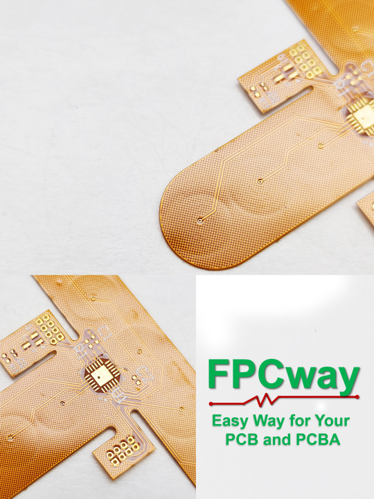
For flexible printed boards with a large number of components and complex wiring relationships, consider the design of mounting retention positions to increase product reliability during structural design.
#pcb#flex pcb#rigid-flex pcb#flex circuit pcb#flexible pcb board#flexible circuit board#fpcway#fpcway.com#www.fpcway.com#today on tumblr#art#artwork#artists on tumblr#digital art
2 notes
·
View notes
Text

4 layers Flex PCB for LCM, Hitech Circuits - top manufacturer from China
It is simple and convenient for workers to hold, solder and other operations. Moreover, the price of flex pcb is relatively cheap, which can reduce production costs; it can play a better insulation effect and ensure the stable operation of 4 layers flexible PCB for LCM.
Technical Parameters
POLYIMIDE material with 4 layers flexible printed circuit board
Outer Copper is 1OZ and Inner Copper is 0.5OZ.
Finished Thickness is 0.2mm for flexible part and 0.4mm for stiffener.
Stiffener: steel
Surface finish: ENIG
Min. trace width/spacing: 0.075/0.075mm
Punching
If you have an inquiry for our service, please contact us, Cynthia<[email protected]>, thank you.
0 notes
Text
FPCway: Specialized manufacturer of flexible printed circuit boards
and rigid-flexible printed circuits
In today's fast-paced technology landscape, the demand for smaller, lighter, and more complex electronic devices continues to rise. Whether it's a sleek smartphone in your pocket or a sophisticated medical device in a hospital, these devices rely on cutting-edge printed circuit boards (PCBS) to run efficiently. Among the many types of printed circuit boards available, flexible printed circuits (flex PCBs) and rigid-flex printed circuits (Rigid-Flex PCBS) are increasingly favored due to their versatility and rich and diverse design possibilities.
Advantages of Flexible Printed Circuit (Flex PCB) :
Space efficiency: Very thin and lightweight, ideal for small electronic devices.
High reliability: Fewer interconnections and solder joints increase reliability and reduce points of failure.
Strong durability: Flexible printed circuits can withstand vibration, shock and extreme temperatures, making them ideal for harsh environments.
Freedom of design: The flexibility of the substrate allows for creative and innovative designs that may not be possible with rigid printed circuits.
Advantages of rigid-flex PCBs:
Space optimization: Flexible printed circuit (Flex PCB) components allow the integration of multiple PCBS and connectors, saving valuable space.
High reliability: Fewer connectors and solder joints reduce the risk of connection failure and signal loss.
Complex geometry: Rigid-flexible printed circuits can be designed to fit non-standard and irregular shaped enclosures.
Reduce weight: Reduce connectors and cables to reduce the overall weight of the device.
FPCway is a PCB manufacturing company located in Shenzhen, China, specializing in the manufacture of flexible printed circuit boards and rigid-flexible printed circuits. The circuit boards produced have been widely used in mobile communication, Internet of Things, optoelectronics, industrial control, medical equipment, consumer electronics and other high-tech industries. The products produced by FPCway are exported to all over the world. At present, FPCway has more than 5000 square meters of FPC workshop, which has 12 SMT production lines and 2 THT production lines. FPCway has more than 200 employees, with more than 20 senior executives with decades of industry experience. With this experience and advanced equipment, we have maintained excellent technical capabilities and strong competitiveness in the Flex PCB industry.
FPCway: From prototype to assembly to product
FPCway provides Flex PCB and rigid-flex PCBs from prototype design to assembly to product, while more than 200 professionals ensure zero defects and the fastest delivery time. The company sources materials from well-known brands and maintains ISO 9001, IATF16949 quality systems and UL certification, facilitating customers' access to commercial products.
Flexible PCB prototype: The production process of FPCB products usually starts from making prototypes, FPCWay almost does not limit the appearance size of FPCB, and can adjust the substrate, thickness and layer number of products according to customer needs.
Flexible PCB assembly: Bring goodness to life
Designing and manufacturing flexible printed circuits (flex PCBs) and rigid-flex PCBS is a highly specialized process that requires specialized knowledge and advanced equipment. Flexible printed circuit (Flex PCB) components are a key step in translating these innovative designs into functional electronic devices. FPCway's engineers consider the flexibility and form factor required by the customer to create a suitable flexible printed circuit (Flex PCB) layout choice; Secondly, the appropriate substrate material is selected based on factors such as flexibility, temperature resistance and intended application. The manufacturer then uses a combination of addition and subtraction processes to create the flexible circuit, which involves etching, drilling, and laminating together. FPCway uses advanced automatic pickers to precisely place components on manufacturing flexible printed circuits (flex PCBs) or rigid-flex PCBS, then apply solder paste to the component pads, heat the components to melt the solder and establish electrical connections. Finally, engineers ensure that flexible printed circuit (Flex PCB) or rigid-flex PCBs components meet quality and functional standards through rigorous testing to ensure that the product has zero defects.
FPCway through the construction of a strong talent team and increase capital investment in the purchase of new equipment, and from prototype design to assembly to the entire process of product accurate control, to ensure product quality, FPCway at a very competitive price to provide first-class service. The company stands out in the flexible printed circuit board industry for its superior technical capabilities, excellent product quality and timely delivery of products.
0 notes
Text
Circuit board and PCB assembly manufacturer from China — Hitech Circuits Co., Limited
What’s Flexible PCB?
Flexible PCB or FPCB is known to be a type of circuit board with many advantages. Most flex PCBs are multilayer PCB.
Compared to traditional rigid PCBs, flex PCB designs usually are more complex and challenging. This type of board can be designed in various ways to achieve the ideal shape for packaging. The flex PCB shape can be in the product when installed.
A flex PCB is unlike any other type of electronic device. It features a combination of thin and flexible substrates and a single component, making design incredibly challenging. When designing the first rigid-flex board, most of the designers had no idea what to expect when it came to designing PCBs.

Why Did Flex PCB Come into Play?
Flex PCBs have arisen to tackle the growing need for more efficient and cost-effective electronic components.
Flexible circuit boards are incredibly versatile because they can be bent and flexed, allowing them to fit into tight spaces that would otherwise be inaccessible with traditional rigid circuit boards.
Flex circuits also provide enhanced protection against vibration, shock, and other environmental factors that can cause damage to traditional rigid circuit boards.
They are also often more lightweight than their rigid counterparts, which explains why they are ideal for use in aircraft or aerospace applications where weight is a significant factor.
Flexible printed circuit boards are used in various applications, from medical devices and automotive systems to consumer electronics and military equipment.
Flex PCBs are becoming increasingly popular, given that they can provide reliable performance in challenging environments while still offering cost-effective solutions.
They also offer all sorts of customization options, allowing for higher levels of performance and design flexibility than traditional rigid circuit boards. Undoubtedly, the flex PCB has a bright future. Thanks to advances in technology and materials, flex PCBs are becoming more reliable and cost-effective. It’s no wonder why they are regarded as an excellent choice for many industries.
Materials of Flex PCB
Substrate and Protective Film
Printed circuit boards commonly used for electronic products are made from glass fibre and epoxy resin. Although rigid is often used to describe these boards, they can feel their elasticity even if one removes a single layer. Due to the cured epoxy resin, these boards can be more rigid, but they cannot be used for specific products because it is not flexible enough. Nevertheless, some products need PCB with this property. It is why it is ideal for those products that are only assembled.
In addition to being used for electronic products, Flexible plastic film is also commonly used in various applications. One of the most common types of plastic film is polyimide, which is very soft and firm. In addition, due to its thermal stability, it can endure temperature changes during reflow welding and resist the effects of deformation and expansion.
Another flexible material type is polyester, commonly used in electronic equipment. Compared to polyimide film, its temperature deformation and heat resistance are worse. This material is usually wrapped in soft films, ideal for printing circuits. Since it cannot withstand high temperatures, cold pressing makes these flexible circuits.
The display part of a clock radio uses a Flexible connection circuit, often working abnormally. The leading cause of this issue is the poor quality of the connector. We recommend using PI film for flex-rigid PCBs to solve this issue.
For flexible circuits, such as those used in electronic devices, various materials, such as PET, PI, and glass fibre core, are used to protect the conductor. In addition, the circuit may also need to use other protective films, such as those designed to protect against corrosion and damage. These can be used to mask solder resist ink. In addition, the insulating film can help prevent the conductor from getting damaged or corrosion.
PET and PI film have a thick film thickness of around 1/3 to 3 mil. The film’s other options are fibreglass or epoxy, typically thicker at 2 to 4 mils.
Although FR4 materials are commonly used for rigid boards, many requirements must be considered when combined with rigid-flex materials.
Someone may claim, “ It’s better to choose the substrate and the covering film with a smaller size contraction and expansion for the materials of flex PCB, right?” Yes, what a point!
Highly flexible and temperature-resistant, polypropylene polyimide (PI) is commonly used in flexible substrates. Its advantages include good mechanical and electrical properties, good moisture absorption, and good weather resistance. But, you may wonder, “Is polyesterimide the most commonly used type?” The answer is yes.
Polyester PET is cheap and has good tear resistance, flexibility, and mechanical properties. Unfortunately, this material’s disadvantages become apparent when heated, as follows.
A significant shrinkage rate
Not ideal for high-temperature soldering due to its high-temperature resistance
Coverlay
Readers familiar with the PCB industry may question, “The purpose of a covering film with a thickness of around 1/2mil to 5 mils is to protect a circuit from moisture, pollution, and soldering. Is that right?” Yes, what a good guess!
The covering film on a PCB is often composed of polyimides, polyester, or polyethylene. The film serves as a mechanical and environmental barrier that protects the copper surfaces from damage during assembly and operations. Depending on the application, the thickness of the protective layer can range from 0.5 mils to 5 mils.A reinforcing film is used to cover a Flex PCB when it’s needed for welding or adding reinforcement. It can be made from various materials such as aluminum, steel, and FR4.
The low-flow PP is commonly used for covering flex-rigid bonding PCBs, such as the Flex-Connect and Rigid. Usually, there are three specifications for this material: 106 (2mil), 1080 (3mil), and 2116 (5mil).
A coverlay film is used to provide excellent mechanical and electrical protection. It’s typically made of polyimide or polyester, which has superior heat resistance and high dielectric properties compared to PP. The thickness of this protective layer can range from 0.5 mils to 5 mils.Most electronic products commonly used for money-saving activities, such as the printing of wires, are still made with copper wire. However, copper foil can be used in different forms when replacing wires and connectors. For instance, copper foil can be the best choice if only to replace the connectors and wires.
In addition, when it comes to improving the carrying capacity of a device, such as a conductor, copper foil can be used by increasing its weight. This material can also achieve a copper sheet width of 1x.
Finally, copper foil is often used to enhance the ability of an insulation material due to its high-frequency characteristics. This allows for better shielding and a reduction in electrostatic interference. Copper foil can also be used as a protective layer between components due to its low-resistance and high dielectric properties compared to PP.Unfortunately, copper is known to be poor at work and causes stress and fatigue. If a flexible circuit needs to be repeatedly shifted or folded to maintain its structural integrity, then copper foil can be the best choice. However, due to its rolling toughness, it can be bent and folded more frequently before fatigue fractures occur.
The increased elasticity of copper foil when it’s rolled can also be used to improve its mechanical properties. For example, this material can extend the life of a Flexible circuit by increasing its rolling toughness.
Adhesive
In addition to copper foil, we must apply adhesive to other films, such as PI film. Due to the different properties of copper foil, such as its hardness, it is impossible to achieve good bonding at high pressure and temperature. Some manufacturers provide copper-clad laminates that are double and single-sided. They use a thickness of one to two mil or one mil of epoxy or acrylic adhesive. It is specially developed for FPC. Due to the increasing popularity of “Glue free” laminates, the need for more efficient processing techniques has led to the development of new materials, such as copper skin on PI films. These materials can be used in large-scale HDI PCB circuits. We will use hot melt, silicone, or epoxy resin when protecting the Flex rigid joints. These two materials will help improve the mechanical strength of the joints and prevent them from experiencing stress fatigue.
Structural Form of Flex PCB
Flex PCBs consist of a thin substrate material with laminated copper conductor layers. Flex circuits can be designed with different configurations, including single-sided, double-sided, and multi-layer boards.
According to Hitechpcb’s experience, flexible circuit boards are typically constructed using three layers of material: an upper core layer made from polyimide or other flexible plastic, an insulating middle layer of either epoxy or silicone; and a bottom conductor layer made of copper. The layers are laminated together using heat and pressure. Flexible printed circuit boards can also be constructed with additional layers to add functionality, such as special shielding for electrical noise or extra conductive circuits for more complex applications.
Production of Flex PCB
The manufacturing process for flexible circuit boards is complex and involves several steps. The first step is to create the circuit design, including components and traces. It can be done either manually or using computer-aided design (CAD) software. Once complete, the design must be printed onto a flexible substrate, typically polyimide film or another similar material. Flexible substrates are ideal for flex PCB production because they allow for curved shapes and thinner trace widths, which are necessary for miniaturization. After the circuit design is printed onto the substrate, it must be cut to size and then laminated with copper foil. Once complete, the flex printed circuit boards are ready for automated assemblies, such as soldering components or attaching connectors.
Flexible PCBs are a versatile and cost-effective way to produce small, lightweight electronics that increase flexibility and reliability. By following the steps outlined above, flex PCB manufacturers can create reliable flex circuits quickly and efficiently. This guide lets you understand how they work and why they are essential to modern electronics production.
Layout of Flex PCB
The design of flex PCBs is complex. Due to the varying signals and energy transmission, it is crucial to consider the various factors that affect the system.
The layout principle of flex PCBs should be followed to minimize the system’s complexity. In addition, the layout of the core components and the essential unit circuits should also be prioritized. The layout should also be arranged according to the signal flow direction of the board.
The overall wiring of the board should be as short as possible. The critical signal lines should also be as short as possible. The decoupling capacitor should be placed as close to the pin of the power supply as possible. The loop connecting the ground and the power supply should also be the shortest. The signal should be run in the correct direction to prevent accidents.
The arrangement of the components should also be convenient for maintenance and debugging. For example, significant components should be placed away from small ones to avoid getting too crowded. Also, there should be enough room around the components to allow debugging.
For circuits with the same structure, the “symmetrical” standard should be adopted as far as possible. In addition, the layout should also be optimized according to the gravity balance and uniform distribution. Founded inChina, Baineng is a leading service platform for the electronic industry.
The electronic industry’s leading online supplier of components, sensors, and printed circuit boards (PCBs) can provide a comprehensive solution to the electronic industry’s supply chain needs. In addition, it allows customers to manage their various requirements through a single platform.
In addition to the usual layout principle, the orientation of the components should also be changed according to the type of board. For instance, the orientation of the plug-in components should be in the X or Y direction.
The heating components should be evenly distributed to minimize the heat generated by the machine and the single board. In addition, temperature-sensitive components should be placed away from significant heat sources.
The signals from high, low, and high currents are entirely separated. In addition, the signals from digital and analog are also separated. Therefore, the high-frequency and low-frequency components should be spaced adequately. It should be noted that the same power supply should be used to place all the components together to facilitate the separation of the power supply in the future.
The layout principle is the most critical aspect of designing a circuit. It involves the placement of the various components and their connection. The priority of the vital signal line should be given to the signals that are most important to the design, such as the small signal, high-speed signal, and synchronization signal.
The density priority principle should also be followed to start wiring the components from the most complex connections on the board.
Considerations for Design Rules of Flex PCB
Compared to the traditional printed circuit board design, the flexible circuit board design is more complex. That’s why the appropriate rules must follow the various aspects of the design. For instance, the transition area and the routing of the board are required to follow the rules of the corresponding design rules.
Through Hole Position
When the flex PCB is bent in dynamic use, the vias should be avoided as much as possible. These are easy to crack and are often the cause of damage. Some people may wonder, “Can we take some measures? For instance, holes can also be punched in the flexible circuit board’s strengthening area, and do not cross the edge line of this area, is that right?” Yes, you are right. It means that when designing flex PCBs, a certain distance should be avoided from the combination area.
The flex-rigid joint area design specifications and the through hole are specified to follow a certain distance. For high-performance applications, the limit is usually set at around 70mil. For processing manufacturers, the limit for vias should be at least 30mil. Follow these rules for both flex and vias. It is the most important rule regarding the combination of Flexible boards.
Design of Pads and Vias
Flexible PCBs require careful consideration when designing the pads and vias. Flexible PCBs are constructed with a non-rigid substrate material, usually polyimide or polyester, allowing them to bend and twist without breaking. However, this flexibility comes at a cost; since the material is not rigid like traditional FR4 substrates, the pads and vias require more precision to ensure they can withstand flexing.
Flexible PCBs often call for unique pad shapes or sizes and special soldering techniques to maximize durability and performance. There is also a need for extra spacing between components and circuitry to prevent short circuits due to strain on the board. These considerations must be considered when designing a flexible PCB, as they will determine the final product’s success. Engineers can produce reliable and effective printed circuit boards by understanding the additional complexities involved with flex PCBs and taking appropriate steps to ensure all design elements are optimized for flexibility.
Routing Design
If there are multiple lines in the Flex area, try to avoid overlapping the paths of the top and bottom layers of the copper wire sheet. It can cause inconsistent stress on the line, leading to mechanical damage. Instead, the paths should be staggered, and the upper and lower layers should be arranged in a straight line.
The design of the Flexible area is similar to that of the rigid area, except that instead of following an angled line, it should follow a circular arc. It can help protect the Flexible board’s lines from getting damaged while bending. The thick and thin lines should also be connected with teardrop-shaped arcs to avoid sudden contraction or expansion.
Copper Laying Design
Some may wonder, “For flexible bending reinforced panels, using a mesh structure with a copper plane layer or lay-up is generally better. Is that right?” The answer is yes. However, for applications such as control of electrical resistance, the electrical quality of the reticulated structure needs to be better. Therefore, the designer should make an informed decision regarding using the reticulated copper sheet. For instance, if the waste area is covered with solid copper paving, the designer should consider designing more solid copper paving.
Distance Between Drilling Hole and Copper Sheet
According to Hitechpcb’s experience, flexible printed circuit boards can accommodate greater distances between the drilled holes and the copper board than conventional rigid boards. The explanation is that the flexible materials used in their construction allow for more complex designs with more detail. As a result, creating designs that necessitate more clearance or space for components can be helpful.
Bending Radius of Bending Area of Flex PCB
As our engineers suggest, the bending radius of the printed circuit board affects the overall performance and reliability of the PCB, given that it determines the amount of pressure which is being applied to the components on the board. Therefore, based on experience, Viaison would design flexible PCBs with suitable material and the correct bending radius to maintain their shape and performance.
Pros and Cons of Flex PCB
Advantages
Flex PCBs allow for greater design flexibility, allowing components to be placed in various configurations.
Flexible circuit boards are much thinner than traditional rigid boards and can conform to almost any shape or space.
Flexible printed circuit boards are lighter, making them easier to transport or install.
They can also reduce the time and cost associated with assembly due to their ability to be easily bent into place without requiring extra hardware or soldering.
Flex circuits are more resistant to shock and vibration because they absorb impact better than other boards.
Flexible PCBs use less material, making them cheaper than other printed circuit boards (PCBs). This results in lower overall costs for production runs requiring many units simultaneously.
Disadvantage
Flex PCBs have some notable disadvantages compared to standard rigid boards. Hitechpcb summarizes the following points.
Flexible PCBs are more expensive than rigid PCBs thanks to their design and manufacturing complexity.
Flex circuits can be more prone to manufacturing defects due to the nature of their construction. Flexible boards require extra testing and QC to ensure the product is made correctly.
Flexible circuit boards require specialized materials and expertise, making them less accessible to small businesses or hobbyists.
Flexible printed circuit boards are less reliable than rigid boards due to their tendency to flex, bend, and twist under pressure or vibration. The same force may cause damage to a flexible board that would not affect a rigid board.
Flexible PCBs require more complex soldering techniques, which can result in reduced yields and increased production costs.
Application of Flex PCB
Wearable Electronics
Flexible Displays
Automotive Applications
Flexible Lighting Solutions
Flexible Heating Elements
Medical Devices and Robotics
Aerospace and Defense
Applications
Solar Panels and Wind Turbines
Industrial Controllers and Sensors
Flexible Implantable Electronics
Conclusion
Flexible PCBs are a great way to add functionality and efficiency to your product designs. So whether you’re looking for greater product design flexibility or more reliable and efficient solutions, it is worth considering integrating flexible printed circuits into your next project. Hitechpcb is a leading flex PCB manufacturer which can provide high-quality flexible PCBs. Welcome to cooperating with us!
0 notes
Text
The Flexible Future of Electronics: Exploring Flexible Circuit Boards
Introduction
In the fast-paced world of electronics, innovation is the name of the game. As our devices become smaller, more powerful, and increasingly integrated into our daily lives, the demand for flexible and adaptable solutions has grown exponentially. One of the key enablers of this revolution is the flexible circuit board, also known as a flexible PCB board or flex circuit PCB. In this blog post, we will dive into the world of flexible circuit boards, exploring what they are, how they work, and their myriad applications across various industries.
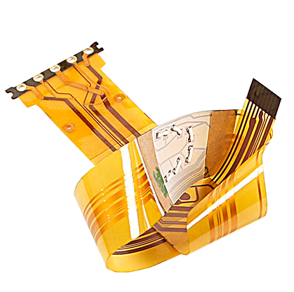
Understanding Flexible Circuit Boards
A flexible circuit board, or flex circuit PCB, is a specialized type of printed circuit board that offers a unique advantage over traditional rigid PCBs – flexibility. While traditional PCBs are typically made from rigid materials like fiberglass or epoxy, flex PCBs are built using flexible materials such as polyimide (PI), polyester (PET), or even a combination of both. This flexibility allows them to be bent, folded, or contoured to fit the specific requirements of a given application.
How Do Flexible Circuit Boards Work?
The basic structure of a flexible circuit board is similar to that of a rigid PCB, consisting of conductive traces, pads, and components. However, the key difference lies in the substrate material. Instead of a rigid substrate, flex PCBs use a flexible material that can withstand repeated bending and flexing without compromising the integrity of the circuit.
Flex PCBs are typically manufactured using a combination of additive and subtractive processes. The process involves printing or etching the conductive traces onto the flexible substrate and then adding the necessary components. The result is a lightweight and compact circuit board that can be shaped to fit the available space.
Applications of Flexible Circuit Boards
Consumer Electronics: Flexible circuit boards are widely used in smartphones, tablets, and wearables. Their flexibility allows for unique form factors and more robust, durable designs.
Automotive Industry: In vehicles, flex PCBs are used in airbags, navigation systems, and instrument clusters. They can withstand the vibrations and temperature fluctuations common in automotive environments. Medical Devices: Flexible circuit boards are crucial in medical devices like pacemakers and medical imaging equipment. Their compact size and flexibility make them ideal for implantable and portable devices.
Click here for more information: https://www.tumblr.com/fpcway/730881884594241536/exploring-the-world-of-rigid-flex-circuit-boards
0 notes
Text
PCB schematic/design/fabrication/assembly
MPN TECH Pte Ltd provides One-Stop PCBA Solutions in Singapore, which support from R&D prototype to mass production. We have built long-term collaborations with many local startups, SIMES, MNCS, etc. We also have lots of overseas PCBA projects in Europe and the US. If any questions feel free to let me know.
Our Solutions:
PCB Design;
PCB Fabrication;
Components souring;
PCB Assembly;(SG Local machine Assembly)
3 notes
·
View notes
Text
PCB Manufacturing in Toronto: Expertise, Services, and Local Industry Insights
Discover PCB manufacturing in Toronto, a hub of innovation and quality in electronic manufacturing services. Learn about the specialized capabilities, technological advancements, and diverse offerings of PCB manufacturers Toronto. Explore how local expertise and cutting-edge facilities contribute to producing high-quality printed circuit boards for various industries and applications worldwide. For more details visit our website www.crimpcircuits.com
#pcb manufacturing toronto#printed circuit board design#metal clad pcb#printed circuits#rigid flex pcb#full turnkey pcb services#turnkey pcb services#pcb parts#eagle software#pcb designing#flexible pcb#pcb assembly#printed circuit board manufacturers#pcb manufacturers in canada#circuit board manufacturers in canada#pcb quote#pcb prototype services in canada
2 notes
·
View notes
Text
What is a Printed Circuit Board?
Printed Circuit Boards are boards that connect various points together through lines and pads. They allow signals and power to connect between two separate physical devices. While the term “printed circuit board” is typically used, other terms to describe these include “printed wiring board” and “printed wiring card.”

#marketing#investing#finance#branding#pcb circuit#pcb#pc build#pcb assembly#flexible circuit board#pcb board fabrication#pcb circuit design#pcb circuit in Gujarat#pcb design company#Printed Circuit Boards
3 notes
·
View notes
Text
PCB Assembly & Electronic Assembly service & electronics manufacturing company – Hitech Circuits Co., Limited As leading one-stop PCB Assembly services provider in China, Hitech Group offers high quality, cost effective and express PCB board products and provides PCB manufacturing, electronics assembly manufacturing, components sourcing, Box build assembly and PCBA testing services for our customers. [email protected] www.hitechcircuits.com
#pcba manufacturing#pcb manufacturer#pcb assembly#flex pcb#pcb fabrication#pcb#pcb factory#smt assembly#flexible circuit board
0 notes
Text
Flex PCB Details Display......
#pcb#flex pcb#rigid-flex pcb#flex circuit pcb#flexible pcb board#flexible circuit board#fpcway#fpcway.com#www.fpcway.com#today on tumblr
0 notes
Text
A flexible printed circuit board (Flex PCB) is a thin, flexible, and bendable circuit board that allows for high-density electronic interconnections in confined spaces. It provides a cost-effective and space-saving solution for electronic devices that require flexibility and portability.
If you are interested, please contact me.


0 notes
Text
Special attention points for flexible circuit wiring
Layer stacking design, device layout, and cutting issues are all obvious, but there are many material weaknesses that can be encountered in flexible circuits.
From relatively high z-axis expansion coefficient adhesives to low viscosity PI substrate copper clad, to copper hardening and fatigue. The following statements of what to do and what not to do will focus on supplementing:
Maintaining the flexibility of the flexible board
It is obvious that the flexibility of the flexible circuit should be determined according to the needs in advance, but it still needs to be emphasized again. If the flexible circuit section is only intended to be folded during assembly and then installed in a fixed position, such as in a handheld ultrasound device, then we have a lot of freedom in choosing the number of layers and the type of copper skin (RA or ED). On the other hand, if the flexible circuit section is to be constantly moved, bent, or rotated, then the number of layers should be reduced and adhesive-free materials should be selected.
We can use IPC-2223B formulas (Formula 1 represents single-sided, Formula 2 represents double-sided, etc.) to determine the minimum allowable bending radius based on the allowable deformation of copper and other material properties.

This example formula is for a single-sided flexible board.
We choose EB based on actual usage conditions, with 16% for applications with little bending, 10% for flexible mounting applications, and 0.3% for dynamic flexible designs.
Do not bend at corners
Generally, we recommend keeping the copper trace of the flexible circuit bent along the vertical direction. But sometimes it's not possible, so try to minimize the bending amplitude and frequency, or use tapered bending according to mechanical design requirements.

Figure 1: Preferred bending location
Use arc routing
As shown in Figure 1 above, it is best to avoid using abrupt right angles or rigidly straight 45° angle traces, but rather to use an arc angle routing pattern. This can reduce the stress on the copper during bending.
Do not suddenly change the width of the trace
When the trace is connected to the pad, especially when arranging and arranging the flexible circuit terminals (as shown in the figure below), a weak force point will be formed, and the copper skin will easily age over time. Unless a reinforcing plate is used or the application process will not bend, it is recommended to use a gradually narrowing connection method such as the one shown below.

Figure 2: Sudden changes in trace width or connections to pads can create weak focal points
Use polygons
it is necessary to place a power supply or ground plane on a flexible board. If you don't mind significantly reducing flexibility and potentially causing the copper skin to wrinkle, you can choose to use solid copper. Generally speaking, it is best to use shadow polygon copper plating to maintain a high degree of flexibility. In mentioning this, I also think that traditional shadow polygons will have excess copper reinforcement in the directions of 0°, 90°, and 45°. A more optimized pattern is the hexagonal approach. This problem can be solved by using negative layer and arrayed hexagonal pads, and the shadow polygon can be established more quickly using copy and paste methods.

Figure 3: Using hexagonal copper plating can evenly balance the stress in three angles.
Provide reinforcement for pads
Due to the use of low-viscosity adhesives (relative to FR-4), copper on flexible circuits is more likely to detach from the polyimide substrate. Therefore, providing reinforcement for exposed copper is particularly important. Coated through holes provide appropriate anchoring for two flexible layers, so using vias is a very good reinforcement method. Because of this (providing z-axis expansion), many processing plants recommend adding coated through holes with depths up to 1.5 mils to rigid-flex boards and flexible circuits. Surface mount pads and non-coated through hole pads do not have reinforcement measures themselves, so additional reinforcement is needed to prevent detachment.

Figure 4: Reinforcement methods for flexible circuit pads, plating, increasing anchors, and reducing cover film openings
Referring to Figure 4, the second option is suitable for adhesive-type cover layers, and the third option is suitable for non-adhesive-type cover layers. Protective films using adhesives may exhibit "overflow" phenomena, so the gap between the pad and the opening must be large enough to ensure excellent soldering formation.
SMT component pads are the most fragile, especially when flexible circuits bend under the rigid pins and pads of the component. Figures 5 and 6 show how to reinforce the pads on both ends of the pad using a cover layer. To achieve this, the pads on the flexible board must be larger than the pads on a typical rigid board.
Looking at the comparison in Figure 6, SMD pads for installing components on a flexible board. This significantly reduces the installation density of flexible circuit components, but compared to rigid circuits, the density of flexible circuits cannot be too high in the first place.

Figure 5: SOW package cover film opening, showing its reinforcement on both ends of each pad. Figure 6: Adjusting pad size and cover layer openings

Figure 6: Adjusting pad size and cover layer openings.
Maintain double-sided flexibility
For dynamic double-sided flexible circuits, try to avoid placing traces in the same direction, but instead need to stagger them (Figure 7) to evenly distribute the copper trace (Figure 8).

Figure 7: Not recommended adjacent layer copper trace routing.

Figure 8: Preferred staggered adjacent layer copper trace routing.
0 notes
Text
Exploring the World of Rigid-Flex Circuit Boards and Flex PCB Prototypes
Introduction
In the ever-evolving world of electronics, innovation is the name of the game. With a constant demand for smaller, more efficient, and versatile electronic devices, manufacturers are continually pushing the boundaries of what's possible. One significant development in this field is the use of flexible printed circuits (FPCs), rigid-flex PCBs, and the intricate process of flex PCB assembly. In this blog post, we will explore these cutting-edge technologies, their applications, and the rigid flex PCB manufacturer behind them.
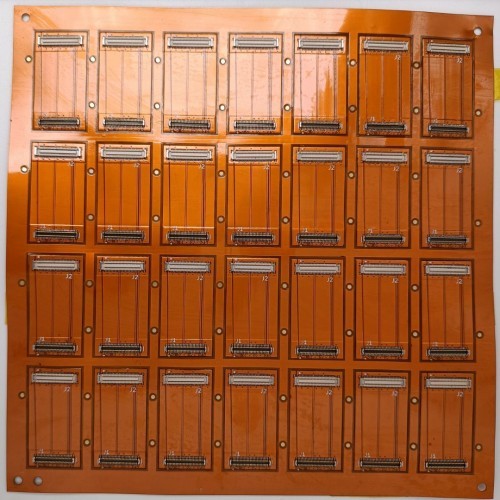
Flexible Printed Circuits (FPCs)
Flexible printed circuits, often referred to as FPCs or flex circuits, are a vital component in modern electronic devices. They offer a flexible alternative to traditional rigid PCBs, making them ideal for applications where space and weight are at a premium. FPCs are constructed using flexible base materials, typically polyimide, and are designed to be thin and lightweight. Here are some key advantages of FPCs:
Space Efficiency: FPCs can be bent and folded to fit into tight spaces, making them invaluable in compact electronic designs.
Weight Reduction: Since FPCs are lightweight, they help reduce the overall weight of electronic devices, a critical consideration in industries like aerospace and automotive.
Reliability: FPCs are known for their high reliability due to the absence of connectors and the reduced risk of solder joint failure.
Complex Shapes: They can be designed in intricate shapes to accommodate specific device designs, which is often challenging with rigid PCBs.
Flexibility: FPCs can withstand millions of flex cycles without compromising their functionality, making them suitable for applications with moving parts.
Rigid-Flex PCBs
Rigid-flex PCBs are a hybrid solution that combines the benefits of both rigid and flexible circuits. They consist of multiple layers of flexible substrates interconnected with rigid PCB sections. This combination allows for complex three-dimensional designs, improved reliability, and reduced assembly time.
Click here for more information: https://www.tumblr.com/fpcway/730768523049205760/the-evolution-of-electronics-flexible-printed
0 notes
Text
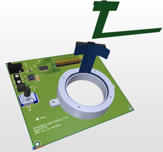
This is another video about the flexible PCB over the rigid PCB without any case.
This is the flexible PCB.
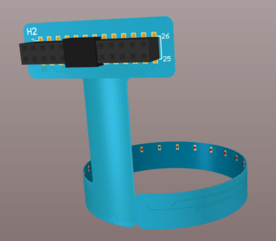

This is the Flex PCB in 2D mode.

This is the Rigid PCB.

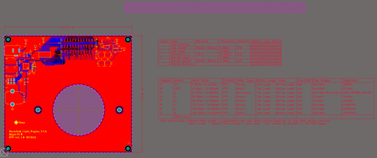
This is the Rigid PCB in 2D mode.
This is the schematic.
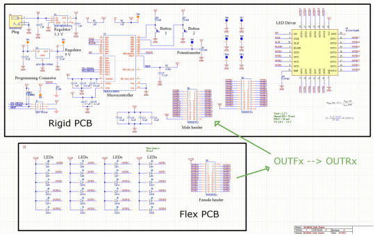
I had to check this project several times before implementing it because I had to be very careful with the corresponding signals.
#electronics#Altium Designer#Altium#flex pcb#pcb assembly#pcb#pcb manufacturer#flexible circuit board
0 notes
Text
Leading PCB Manufacturers in Canada: Quality and Innovation
Discover the top PCB manufacturers in Canada that specialize in providing high-quality printed circuit boards for various industries, including aerospace, automotive, medical, and consumer electronics. These companies offer a range of services, from prototype development to mass production, ensuring precision engineering and compliance with international standards. With state-of-the-art technology and skilled professionals, Canadian PCB manufacturers are committed to delivering innovative solutions, fast turnaround times, and exceptional customer service. Partner with these trusted manufacturers to meet your electronic design and manufacturing needs.
#pcb manufacturing toronto#printed circuit board design#metal clad pcb#printed circuits#rigid flex pcb#full turnkey pcb services#turnkey pcb services#pcb parts#eagle software#pcb designing#flexible pcb#pcb assembly#printed circuit board manufacturers#pcb manufacturers in canada#circuit board manufacturers in canada#pcb quote#pcb prototype services in canada
0 notes
Text
How to Select the Right Flexible PCB Manufacturer for Your Product
As stated earlier, searching for the ideal flexible PCB supplier can be tricky, but once you get the hang of the methods we’ll cover in a bit, it should become significantly easier to find them. Listed down here are the factors you’ll need to consider before settling for a flex PCB supplier so that you’ll end up with the supplier that meets your standards. Pcbcircuit is one of the Top PCB manufacturers in India, offering affordable prices .

#marketing#investing#pcb#flexible circuit board#pcb manufacturer#PCBcircuit#pcbmanufacturing#electronics#circuit#manufacturing#manufacturer#pcbdesign#pcbassembly#pcbmanufacturer
0 notes