#i2c controller ip
Explore tagged Tumblr posts
Visit Tumblr Blog
Explore Tumblr blogs with no restrictions, modern design and the best experience.
Last Seen Tumblr Blogs


Fun Fact
The average Tumblr user visits about 67 pages every month.
Text

AXI4 Stream DMA IP
Optimize Data Transfer with the AXI4 Stream DMA IP Block Say goodbye to cumbersome data transfer processes and hello to seamless efficiency with our AXI4 Stream DMA IP block! Built to optimize data transfer within your digital system, this lightweight module enables swift and reliable communication between different components. Whether you're working on complex multi-channel audio or video processing, our AXI4 Stream DMA IP block ensures precise and efficient data handling every step of the way. Upgrade your system's performance and enhance your workflow with this high-performance IP block now!
#i3c controller ip#display controller ip#i3c master#lcd controller ip#axi dma scatter gather#i2c controller ip#i2c master ip#espi ip#i2c slave ip#axi dma ip
0 notes
Text
raspberry pi pc
Yes, a Raspberry Pi would indeed work much better than an Arduino for implementing a system where two "computers" are communicating and learning from each other. The Raspberry Pi is a full-fledged single-board computer (SBC), which means it has far greater processing power, memory, and capabilities compared to an Arduino. This makes it much more suitable for complex tasks like data processing, machine learning, and communication between two devices.
Key Differences Between Arduino and Raspberry Pi for This Task:
1. Processing Power:
Arduino: Limited to simple microcontroller tasks (e.g., simple sensors, I/O operations, small control tasks). It has very little computational power and memory (e.g., 2 KB of RAM, 32 KB of flash memory).
Raspberry Pi: Has a powerful CPU, much more memory (e.g., 4 GB or 8 GB of RAM on newer models), and can run a full Linux-based operating system (e.g., Raspberry Pi OS). This makes it suitable for tasks like running machine learning models, more complex algorithms, and networking tasks.
2. Communication:
Arduino: Can communicate using simple protocols like Serial, I2C, or SPI, which are ideal for small-scale, low-speed communication between devices.
Raspberry Pi: Has multiple communication options including Ethernet, Wi-Fi, and Bluetooth, along with more advanced serial protocols. It can communicate over a local network or even the internet, making it ideal for real-time communication between two "computers."
3. Storage and Software:
Arduino: Does not have a storage system other than its limited onboard memory (though you can use SD cards for small amounts of storage). The code running on an Arduino is typically bare-metal (no operating system), and it can only run a single program at a time.
Raspberry Pi: Has access to a large amount of storage (via microSD card or external storage), and runs a full operating system, allowing you to install software libraries, run multiple processes simultaneously, and use advanced tools and frameworks for communication and learning (e.g., TensorFlow, OpenCV, etc.).
4. Machine Learning and Data Processing:
Arduino: You can implement simple algorithms (like decision trees or basic pattern recognition), but it’s not suited for real-time machine learning or complex data analysis.
Raspberry Pi: Can run machine learning models, handle large datasets, and run frameworks like TensorFlow, PyTorch, scikit-learn, etc. This makes it much more capable of "learning" from data, making decisions, and adapting based on feedback.
5. How a Raspberry Pi PC System Could Work Better
Given that Raspberry Pi is a full-fledged computer, you can implement the original idea of two computers communicating and learning from each other in a much more robust way. Here’s how you can achieve that:
Hardware Setup for Raspberry Pi PCs:
Two Raspberry Pi boards (e.g., Raspberry Pi 4, Raspberry Pi 3, or even Raspberry Pi Zero for smaller setups).
Display, keyboard, and mouse for local interaction, or run everything remotely via SSH (headless).
Networking: Use Wi-Fi or Ethernet to connect the two Raspberry Pi boards and enable communication.
Optional: Camera, microphone, sensors, or other input/output devices for more advanced interaction and learning tasks.
Communication Between Raspberry Pi PCs:
You can use several methods for communication between the two Raspberry Pi boards:
TCP/IP Communication: Set up a client-server model, where one Raspberry Pi acts as the server and the other as the client. They can communicate over a local network using sockets.
MQTT: A lightweight messaging protocol suitable for device-to-device communication, commonly used in IoT.
HTTP/REST APIs: You can use a web framework (e.g., Flask, FastAPI) to create APIs on each Raspberry Pi, allowing them to communicate via HTTP requests and responses.
WebSocket: For real-time bidirectional communication, you can use WebSockets.
Software/Frameworks for Machine Learning:
You can install frameworks like TensorFlow, Keras, or scikit-learn on the Raspberry Pi to allow for more advanced learning tasks.
Use Python as the programming language to communicate between the two Pi boards and implement machine learning algorithms.
Raspberry Pi can interact with real-world data (e.g., sensors, cameras, etc.) and learn from it by running algorithms like reinforcement learning, supervised learning, or unsupervised learning.
6. Example Use Case: Two Raspberry Pi PCs Learning from Each Other
Here’s an example scenario where two Raspberry Pi boards communicate and learn from each other using TCP/IP communication and basic machine learning (e.g., reinforcement learning).
Raspberry Pi 1 (PC1): This board makes a decision based on its current state (e.g., it guesses a number or makes a recommendation).
Raspberry Pi 2 (PC2): This board evaluates the decision made by PC1 and sends feedback. PC2 might "reward" or "punish" PC1 based on whether the decision was correct (e.g., in a game or optimization problem).
Feedback Loop: PC1 uses the feedback from PC2 to adjust its behavior and improve its future decisions.
Example Architecture:
PC1 (Raspberry Pi 1):
Makes a guess (e.g., guesses a number or makes a recommendation).
Sends the guess to PC2 via TCP/IP.
Receives feedback from PC2 about the quality of the guess.
Updates its model/behavior based on the feedback.
PC2 (Raspberry Pi 2):
Receives the guess or recommendation from PC1.
Evaluates the guess (e.g., checks if it’s close to the correct answer).
Sends feedback to PC1 (e.g., positive or negative reinforcement).
Basic Python Code for TCP Communication:
On both Raspberry Pis, you can use Python’s socket library to establish a client-server communication:
PC1 (Server) Code:
import socket import random # Create a TCP/IP socket server_socket = socket.socket(socket.AF_INET, socket.SOCK_STREAM) server_socket.bind(('0.0.0.0', 65432)) # Bind to any address, port 65432 server_socket.listen(1) print("PC1: Waiting for connection...") connection, client_address = server_socket.accept() print("PC1: Connected to PC2") while True: # Simulate a decision (e.g., guessing a number) guess = random.randint(1, 100) print(f"PC1: Guessing number {guess}") # Send the guess to PC2 connection.sendall(str(guess).encode()) # Wait for feedback from PC2 feedback = connection.recv(1024).decode() print(f"PC1: Received feedback: {feedback}") # Adjust behavior based on feedback (simple learning mechanism) if feedback == "correct": print("PC1: Correct guess!") else: print("PC1: Incorrect guess, trying again.") # Wait before making another guess time.sleep(2)
PC2 (Client) Code:
import socket # Create a TCP/IP socket client_socket = socket.socket(socket.AF_INET, socket.SOCK_STREAM) client_socket.connect(('PC1_IP_ADDRESS', 65432)) # Connect to PC1 while True: # Receive the guess from PC1 guess = int(client_socket.recv(1024).decode()) print(f"PC2: Received guess {guess}") # Evaluate the guess (simple decision: correct if guess is 50) if guess == 50: feedback = "correct" else: feedback = "incorrect" # Send feedback to PC1 client_socket.sendall(feedback.encode()) print(f"PC2: Sent feedback: {feedback}")
7. Expanding This System
Advanced Communication: If you're looking for real-time interaction, you can explore using WebSockets or MQTT for more efficient, bidirectional communication.
Machine Learning: You can train models on both Raspberry Pi devices, where one device sends data to the other for training, and they both improve over time.
Distributed Systems: With two Raspberry Pis, you can build a distributed system where each Pi runs part of the computation, and they collaborate to solve more complex tasks.
Conclusion:
Raspberry Pi is definitely a better choice for the task of two computers communicating and learning from each other, as it offers the computational power, memory, and flexibility needed for machine learning, real-time communication, and more advanced systems. The Arduino is more suitable for simple tasks and small embedded systems, whereas the Raspberry Pi can handle much more complex processing, communication, and learning systems.
If you want to build a more advanced learning system, I would recommend using Raspberry Pi boards. Would you like to dive deeper into a specific part of the setup or need help with more advanced machine learning on Raspberry Pi?
Creating a Raspberry Pi-based PC involves setting up a Raspberry Pi board to function as a full desktop computer, capable of running an operating system, connecting to the internet, and supporting peripherals like a keyboard, mouse, and display. Unlike an Arduino, which is used for embedded systems, a Raspberry Pi is a full-fledged computer, making it much easier to set up as a personal computer.
Here’s a step-by-step guide on how to turn a Raspberry Pi into a fully functional PC.
What You Need:
Raspberry Pi Board (e.g., Raspberry Pi 4, Raspberry Pi 3, or Raspberry Pi Zero)
MicroSD Card (at least 8 GB, recommended 16 GB or more) for the operating system
Power Supply (5V 3A USB-C for Raspberry Pi 4, or appropriate power for other models)
HDMI Cable and a Display (HDMI-compatible monitor or TV)
Keyboard and Mouse (USB or Bluetooth, depending on your preference)
Internet connection (Ethernet cable or Wi-Fi)
USB storage (optional, for additional storage)
MicroSD card reader (for flashing the operating system)
Step-by-Step Guide:
1. Prepare the MicroSD Card with Raspberry Pi OS
First, you'll need to install the operating system on your MicroSD card. The most common and recommended OS for Raspberry Pi is Raspberry Pi OS (formerly Raspbian).
Download Raspberry Pi Imager: Visit Raspberry Pi’s official website and download the Raspberry Pi Imager for your computer (Windows, macOS, or Linux).
Install Raspberry Pi OS:
Open the Raspberry Pi Imager, select "Choose OS", and select Raspberry Pi OS (32-bit) (recommended for most users).
Select your MicroSD card as the target.
Click Write to flash the OS onto the SD card.
Enable SSH or Wi-Fi (Optional): If you plan to use the Raspberry Pi headlessly (without a monitor, keyboard, or mouse), you can enable SSH or configure Wi-Fi before inserting the SD card into the Pi:
After flashing, insert the SD card into your computer.
Open the boot partition and create an empty file named "ssh" (no extension) to enable SSH.
For Wi-Fi, create a file called wpa_supplicant.conf with your Wi-Fi credentials: country=US ctrl_interface=DIR=/var/run/wpa_supplicant GROUP=netdev update_config=1 network={ ssid="Your_SSID" psk="Your_Password" }
2. Set Up the Raspberry Pi
Insert the SD card into the Raspberry Pi.
Connect your HDMI cable from the Raspberry Pi to the monitor.
Plug in your keyboard and mouse via the USB ports.
Connect the power supply to the Raspberry Pi.
3. First Boot and Raspberry Pi OS Setup
When you power on the Raspberry Pi, it should boot into Raspberry Pi OS.
Follow the on-screen instructions to:
Set up your language, timezone, and keyboard layout.
Set up your Wi-Fi connection (if not already done).
Update the system by running sudo apt update and sudo apt upgrade in the terminal.
4. Install Additional Software
Once your Raspberry Pi is running, you can install additional software based on your needs. For example:
Web Browsing: The default browser is Chromium, but you can install others like Firefox.
Office Suite: Install LibreOffice for document editing, spreadsheets, and presentations.
Command: sudo apt install libreoffice
Development Tools: If you want to use the Pi for programming, you can install IDEs like Thonny (for Python) or Visual Studio Code.
Command: sudo apt install code
Media Software: You can use VLC for media playback or Kodi for a home theater system.
5. Optimize Your Setup
To make your Raspberry Pi run smoothly and feel more like a desktop PC:
Increase Memory Allocation: If you're using a Raspberry Pi 4, you can allocate more memory to the GPU via sudo raspi-config.
Enable Auto-Login: To skip the login screen on boot, you can configure auto-login:
Run sudo raspi-config.
Select Boot Options → Desktop/CLI → Desktop Autologin.
Configure Performance Settings: You can tweak performance settings like CPU overclocking or enabling hardware acceleration for graphics in the Raspberry Pi configuration tool (raspi-config).
6. Optional: Adding a Large Storage Device
If the 8 GB or 16 GB of storage on the SD card isn’t enough, you can plug in a USB hard drive or USB flash drive to expand your storage. You can also configure the Raspberry Pi to boot from a USB drive (for faster performance compared to an SD card).
7. Set Up Remote Access (Optional)
If you prefer to control the Raspberry Pi from another computer:
SSH: You can access the Raspberry Pi's terminal remotely via SSH (if enabled during setup). To connect, use a tool like PuTTY (Windows) or the terminal (Linux/macOS):
Command: ssh pi@<raspberrypi-ip-address>
VNC: You can use VNC for remote desktop access.
Enable VNC using sudo raspi-config.
Download and install RealVNC on your computer to access the Raspberry Pi’s graphical desktop remotely.
8. Using Your Raspberry Pi as a Full PC
Once you’ve completed the setup, your Raspberry Pi will be ready to use like a regular desktop computer. You can:
Surf the web, check emails, and use social media with browsers like Chromium or Firefox.
Write documents, create spreadsheets, and presentations using LibreOffice.
Code in multiple languages (Python, Java, C++, etc.).
Play media files with VLC or stream content using Kodi.
9. Advanced Uses: Building a Raspberry Pi "Server"
If you want your Raspberry Pi to act as a server or take on additional tasks, you can configure it for various roles:
Home Automation: Set up a Home Assistant or OpenHAB server for smart home automation.
Web Server: You can install Apache or Nginx and run a web server.
Command: sudo apt install apache2
Cloud Server: Set up Nextcloud or ownCloud to create your own cloud storage.
Conclusion
Creating a Raspberry Pi PC is a great way to repurpose the Raspberry Pi as a low-cost, energy-efficient desktop computer. Whether you're using it for everyday tasks like browsing, programming, or media consumption, or even more advanced tasks like running servers or learning about Linux, the Raspberry Pi is incredibly versatile.
If you need help with specific configurations, software installation, or troubleshooting, feel free to ask!
0 notes
Text
PiSquare: RP2040 & ESP-12E-based board for all Raspberry Pi HATs
PiSquare is a compact, wireless communication board designed for Raspberry Pi that enables you to wirelessly connect and communicate with multiple Raspberry Pi HATs including SPI, I2C, and SPI HATs. It is based on two powerful components:
⦁ The RP2040 microcontroller (the same chip used in the Raspberry Pi Pico). ⦁ The ESP-12E Wi-Fi module for seamless wireless communication.
By using socket programming, PiSquare can wirelessly interact with Raspberry Pi HATs through TCP/IP communication, allowing you to connect as many devices as you need, without worrying about physical stacking or GPIO conflicts.
Key Specifications:
⦁ Microcontroller: Raspberry Pi RP2040
Core Architecture: Dual-core ARM Cortex-M0+ microcontroller
Clock Speed: Up to 133 MHz
Flash Memory: 2MB onboard QSPI Flash (for program storage)
RAM: 264KB SRAM
GPIO Pins: 26 multi-function GPIO pins with support for PWM, SPI, I2C, UART, and other peripherals
⦁ Wi-Fi Connectivity: ESP-12E
Wi-Fi Standard: 802.11 b/g/n
Wireless Frequency: 2.4 GHz
Wi-Fi Chipset: ESP8266 (with 4MB of onboard Flash)
Data Rate: Up to 72.2 Mbps (with 802.11n support)
Communication Interface: UART (Universal Asynchronous Receiver Transmitter)
⦁ Wireless Communication via Socket Programming
Protocol: TCP/IP (Transmission Control Protocol/Internet Protocol) via socket programming
Connection Type: Full-duplex, bi-directional communication
Network Type: Local Area Network (LAN) or Wi-Fi based network for device communication
Number of Supported Devices: Configurable for communication with multiple (n) Raspberry Pi HATs over Wi-Fi without the need for physical stacking
Socket Layer: Raw socket-based communication for sending and receiving data over the network
⦁ HAT Compatibility
Supported Protocols: SPI (Serial Peripheral Interface): Full-duplex, synchronous communication for connecting peripherals
I2C (Inter-Integrated Circuit): Multi-master, multi-slave communication for sensors, actuators, and peripheral devices
GPIO-based HATs: Supports a variety of devices and sensors with GPIO pin control
Pin Multiplexing: Flexible I/O pin assignment allowing for easy configuration of multiple communication protocols simultaneously
Addressing: Supports unique addressing for SPI and I2C devices to avoid conflicts
⦁ Power Supply
Voltage: 5V DC ±5% (typical operating voltage range)
Power Consumption: Low-power operation suitable for remote or battery-powered applications
Regulation: Onboard linear voltage regulator to provide stable power for the microcontroller and Wi-Fi module
⦁ Form Factor
Dimensions: 65mm x 30mm x 20mm (compact design suitable for integration into small devices)
Mounting: Compatible with standard Raspberry Pi connectors (via external interface) without the need for physical GPIO stacking
⦁ I/O and Expansion
Interface: UART, SPI, I2C (for communication with external peripherals)
GPIO: 26 GPIO pins for signal input/output, including support for digital, analog, PWM, and interrupts
Use Cases
Here are a few ways PiSquare can revolutionize your Raspberry Pi projects:
Multi-HAT Robotics: Easily connect multiple HATs for motor control, sensor arrays, and communication modules in a wireless setup.
IoT Projects: PiSquare can communicate with several sensor HATs in remote locations, sending data back to a central Raspberry Pi for processing or cloud storage.
Home Automation: Connect a variety of home automation HATs wirelessly, creating a smart home system that’s efficient and scalable.
Distributed Sensor Networks: Set up multiple sensors across a large area without worrying about physical connections or pin conflicts.
The Pisquare RP2040 with the onboard ESP-12E Wi-Fi module is a powerful and compact solution for anyone looking to build wireless IoT projects. Its support for multiple HATs, including SPI and I2C, makes it versatile enough to handle a wide variety of peripherals, while its ability to implement socket programming provides you with the flexibility to create robust networked applications.
Whether you're creating a smart home system, an industrial IoT device, or a robotics project, the Pisquare by SB Components can be the perfect foundation for your next creation.
#technology#raspberry pi#innovation#tech#techinnovation#programming#tech projects#projects#artificial intelligence#technews
0 notes
Text
ATMEGA128-16AI Datasheet, Features, Pinout, and Applications
Update Time: Jun 20, 2024 Readership: 321
Overview of the ATMEGA128-16AI
The ATMEGA128-16AI is a highly integrated microcontroller, equipped with a rich set of peripherals and a robust instruction set, making it suitable for a wide range of applications from industrial automation to consumer electronics.
Specifications and Features
ATMEGA128-16AI Specifications
Core: 8-bit AVR
Flash Memory: 128 KB
SRAM: 4 KB
EEPROM: 4 KB
Clock Speed: Up to 16 MHz
Operating Voltage: 4.5V to 5.5V
Package: 64-pin TQFP
Operating Temperature Range: -40°C to 85°C
ATMEGA128-16AI Features
High-Performance AVR RISC Architecture: 133 Powerful Instructions
Peripheral Features: 53 Programmable I/O Lines, 8-channel 10-bit ADC, 4 PWM Channels
Timers: 4 Timer/Counters
Communication Interfaces: USART, SPI, TWI (I2C)
Power Management: Multiple Sleep Modes, Power-on Reset, Brown-out Detection
Development Support: JTAG Interface for On-Chip Debugging
ATMEGA128-16AI Pinout
Pin NameDescriptionFunctionVCCPower SupplyPowers the microcontrollerGNDGroundGround reference for the microcontrollerPORTAPA[0:7]Port A: Analog Inputs/General Purpose I/OPORTBPB[0:7]Port B: General Purpose I/OPORTCPC[0:7]Port C: General Purpose I/OPORTDPD[0:7]Port D: General Purpose I/OPORTEPE[0:7]Port E: General Purpose I/OPORTFPF[0:7]Port F: General Purpose I/OPORTGPG[0:4]Port G: General Purpose I/ORESETResetResets the microcontrollerXTAL1Crystal OscillatorExternal clock inputXTAL2Crystal OscillatorExternal clock outputAVCCAnalog SupplyPowers the ADCAREFAnalog ReferenceReference voltage for the ADCADC[0:7]Analog InputsInputs for the Analog-to-Digital ConverterJTAGJTAG InterfaceFor debugging and programmingTWISCL, SDAI2C Communication LinesUSARTTXD, RXDUART Communication LinesSPIMISO, MOSI, SCK, SSSPI Communication Lines
ATMEGA128-16AI Applications
Embedded Systems
The ATMEGA128-16AI is widely used in embedded systems for applications such as robotics, automation, and control systems, thanks to its rich set of peripherals and robust performance.
Industrial Automation
In industrial automation, the ATMEGA128-16AI provides the processing power and flexibility needed for controlling machinery, monitoring processes, and interfacing with sensors and actuators.
Consumer Electronics
This microcontroller is also found in consumer electronics, where it helps manage functions in devices like remote controls, home automation systems, and portable gadgets.
Automotive Systems
In automotive applications, the ATMEGA128-16AI can be used for engine control units (ECUs), infotainment systems, and other in-vehicle electronics requiring reliable and efficient operation.
Communication Systems
The ATMEGA128-16AI supports multiple communication protocols, making it suitable for use in networking and communication systems where reliable data transfer is crucial.
ATMEGA128-16AI Package
The ATMEGA128-16AI is available in a 64-pin TQFP package, which supports surface-mount technology (SMT). This package facilitates high-density PCB designs and efficient use of board space.
ATMEGA128-16AI Manufacturer
The ATMEGA128-16AI is manufactured by Microchip Technology, a leading provider of microcontroller, mixed-signal, analog, and Flash-IP solutions. Microchip offers extensive support and documentation for the ATMEGA128-16AI, ensuring ease of use and integration into electronic designs.
ATMEGA128-16AI Datasheet
Download ATMEGA128-16AI datasheet.
Conclusion
The ATMEGA128-16AI is a versatile and efficient microcontroller, suitable for a wide range of applications, from embedded systems to industrial automation and consumer electronics. Its combination of high performance, rich peripheral set, and robust development support makes it a valuable component in electronic designs. Microchip's commitment to quality ensures the ATMEGA128-16AI provides consistent and dependable results in various environments.
0 notes
Text
Improving Design Productivity and Quality with Specification Automation

Designing semiconductor devices has always been a distinct specialty of engineering, but today’s designers face immeasurably greater challenges. A typical system-on-chip (SoC) design has billions of transistors, thousands of intellectual property (IP) blocks, hundreds of I/O channels, and dozens of embedded processors. Chip designers need all the help they can get.
Three Keys for Faster, Better Design
Assistance comes in three forms: abstraction, automation, and reuse. Virtually all chip design today occurs at the register transfer level (RTL), enabling much greater productivity than manually crafting gates or transistors. This level of abstraction is therefore much more efficient, making it possible for a single designer to create entire IP blocks or even subsystems.
RTL design is also amenable to automation; generating gate-level netlists automatically via logic synthesis is part of what makes the design process so efficient and productive. Just about every aspect of the test insertion, power management, layout, and signoff flow that follows RTL design is automated as well. Without this approach, modern SoCs simply would not be possible.
The third form of assistance is design reuse. Especially for standard IP blocks and interfaces, there is no value-add in reinventing the wheel by designing from scratch. EDA vendors and dedicated IP providers offer a huge range of reusable designs, most in RTL form. Designers often need this IP to be configurable and customizable, so it may come from a generator rather than as a fixed design.
Register Automation Is the Foundation
All three forms of designer assistance come together in specification automation, starting with the registers in the design. SoCs typically have a huge number of addressable (memory-mapped) registers defined by the chip specifications. These registers form the hardware-software interface (HSI) by which the embedded software and system drivers control the operation of the hardware.
Manually writing RTL code for all these registers is tedious and error-prone. Fortunately, the Agnisys IDesignSpec™ Suite makes it easy to automatically generate the register RTL design. Using the IDesignSpec GDI interactive tool or the IDS-Batch™ CLI Batch Tool, designers create their RTL files at the push of a button every time the register specification changes.
These tools accept many register and memory specification formats, including spreadsheets, SystemRDL, IP-XCAT, and the Portable Stimulus Standard (PSS). Designers can specify many widely used special register types, including indirect, indexed, read-only/write-only, alias, lock, shadow, FIFO, buffer, interrupt, counter, paged, virtual, external, and read/write pairs.

Registers are just one part of a chip that can be specified abstractly and generated automatically, fostering reuse and improving quality of results (QoR) with proven design IP. Another example is interfaces to standard buses such as APB, AHB, AHB-Lite, AXI4, AXI4-Lite, TileLink, Avalon, and Wishbone. The RTL design generated by IDesignSpec Suite includes any interfaces requested.
Any necessary clock-domain-crossing (CDC) logic across asynchronous clock boundaries is also included in the generated design. For safety-critical chip applications, designers can request that safety mechanisms such as parity, error-correcting code (ECC), cyclic redundancy check (CRC), and triple module redundancy (TMR) logic be included as well.
Most chips contain standard design elements such as AES, DMA, GPIO, I2C, I2S, PIC, PWM, SPI, Timer, and UART. Designers specify these blocks with many degrees of configuration and customization, and the Agnisys IDS-IPGen™ design tool generates the RTL design code. IDS-IPGen also generates finite state machines (FSMs) and other design elements for custom IP blocks.

Automating SoC Assembly
As noted earlier, SoCs contain thousands of standard and custom IP blocks. All of these must be connected together into the top-level chip design. Like register design, manually writing the RTL code for this stage is a tedious and error-prone process. Block inputs and outputs change many times over the course of a project, and updating the top-level RTL code by hand is extremely inefficient.
The Agnisys IDS-Integrate™ design tool, another part of the IDesignSpec Suite, automates the chip assembly process. Designers specify the desired hookup using a simple but powerful format that includes wildcards to handle buses and collections of signals with similar names. IDS-Integrate automatically generates the complete top-level RTL design.
For IP blocks with standard buses, IDS-Integrate automatically generates any required aggregators, bridges, and multiplexors, including them in the top-level RTL design. For example:
AHB interfaces on two IP blocks can be aggregated into a single bus
An AHB-to-APB bridge can connect IP using AHB and IP using APB

With the burden on SoC designers growing all the time, they need to specify at the highest possible level of abstraction, take advantage of automation, and reuse whenever possible. The specification automation capabilities of the Agnisys IDesignSpec Suite provide all three forms of designer assistance, providing the industry’s most complete solution.
Designers no longer have to hand-write RTL code for registers, memories, standard bus interfaces, aggregators, and bridges, CDC logic, safety mechanisms, custom IP elements, standard IP blocks, and top-level design. Abstract specification and automation improves productivity; reuse of proven IP improves quality of results.
Customization and configuration options ensure that designers do not have to sacrifice any flexibility to achieve these benefits. Many other project teams—verification, validation, embedded software, bringup, and documentation—also benefit from specification automation. The reasons to select Agnisys as a design partner are truly compelling.
0 notes
Text
ESP8266 Wifi Module | Nodemcu ESP8266 for IoT Solution
The Internet of Things (IoT) is revolutionizing the way we interact with technology, making our lives smarter and more efficient. At the heart of this revolution is the ESP8266 WiFi module, a low-cost, powerful solution perfect for your IoT projects. Whether you're a hobbyist, a professional developer, or a business looking to integrate smart technology into your products, the ESP8266 WiFi module offers unmatched versatility and performance. Here's why you should consider buying the ESP8266 WiFi module and how the NodeMCU ESP8266 can be your gateway to a myriad of IoT solutions.
What is the ESP8266 WiFi Module?
The ESP8266 is a highly integrated chip designed for the needs of a new connected world. It offers a complete and self-contained WiFi networking solution, allowing it to either host the application or offload all WiFi networking functions from another application processor. With its low cost and high performance, the ESP8266 WiFi module has become a popular choice among IoT developers.
ESP8266 NodeMcu WiFi Development Board Features:-
It is based on ESP8266, integates GPIO, PWM, IIC, 1-Wire and ADC all in one board.
Power your developement in the fastest way combinating with NodeMCU Firmware!
USB-TTL included, plug&play
10 GPIO, every GPIO can be PWM, I2C, 1-wire
Open source IoT Platform
Easily Programmable
Low cost & Simple to Implement
WI-FI enabled
ESP8266 NodeMcu WiFi Development Board Applications:-
Home Appliances
Home Automation
Smart Plug and lights
Mesh Network
Industrial Wireless Control
Baby Monitors
IP Cameras
Sensor Networks
Wearable Electronics
Why Choose NodeMCU ESP8266 for Your IoT Projects?
Ease of Use: NodeMCU's integrated USB-to-serial interface and pre-flashed firmware allow for immediate programming and development.
Versatile Programming: You can program the NodeMCU using the Arduino IDE or NodeMCU’s native Lua scripting language, giving you flexibility in development.
Wide Community Support: As one of the most popular IoT development platforms, NodeMCU has extensive documentation and a large community, making it easier to find support and resources.
Cost-Effective: NodeMCU provides a highly cost-effective solution for IoT development, offering excellent value for money.
Rapid Prototyping: Its comprehensive feature set and ease of use make NodeMCU ideal for rapid prototyping and deployment of IoT solutions.
Conclusion
Purchase Your ESP8266 and NodeMCU ESP8266 Today!
Don't miss out on the opportunity to enhance your IoT projects with the best technology available. Purchase your ESP8266 WiFi module and NodeMCU ESP8266 development board today and join the growing community of IoT developers who are shaping the future of technology.
Innovation awaits at Campus Component, where you can buy genuine ESP8266 NodeMCU boards at competitive prices. Take the first step towards realizing your IoT dreams and explore the endless possibilities of connected devices. Order now and join the IoT revolution with Campus Component as your trusted partner.
0 notes
Text
Peripheral IP Cores Targeting Automotive Applications for Reliable Performance
T2MIP, the global independent semiconductor IP Cores provider & Technology experts, a leading provider of electronic design services and IP solutions, is proud to offer a comprehensive range of Peripheral IP cores, including CAN, LIN, UART, SPI, and I2C. These IP Cores have been in Production in multiple chipsets with a robust and high-speed interface.
Peripherals IP cores such as CAN Bus, LIN Bus, UART, SPI and I2C IPs for automotive are designed to increase and expand a computer's functionality without changing the system's essential parts. These IP cores are essential building blocks for any embedded system, enabling communication between various devices and facilitating data transfer between different subsystems. With our cutting-edge IP cores, designers can achieve higher performance, greater flexibility, and improved reliability in their designs.
CAN (Controller Area Network) is a widely used communication protocol that enables the exchange of data between multiple devices in real-time. Our CAN IP cores is designed to be highly configurable and scalable, making it a versatile solution for a wide range of applications. We have CAN FD, CAN 2.0 and CAN XL available for automation.
The LIN bus is a polled bus with one master device and one or more slave devices. Both a master task and a slave task are present on the master device. With one slave job on each slave device. The master task in the master device controls all aspects of communication across the LIN bus. Our LIN IP cores provides robust and reliable communication between devices, with support for a variety of LIN versions and modes.
In UART communication, the transmitting UART transforms parallel data into the serial form, sends it serially to the receiving UART, and the latter transforms the serial data back into parallel data. Our UART IP cores offers high-speed, reliable communication with low power consumption, making it an ideal solution for many applications.

SPI is primarily utilized by a device to communicate between various circuit components. between a controller and peripheral ICs. Our SPI IP cores offers support for multiple devices and configurations, making it a highly flexible solution for a wide range of applications. We have the other versions of SPI eSPI, QSPI and FSPI for the automation.
I2C (Inter-Integrated Circuit) is a two-wire communication protocol commonly used in low-speed applications. Our I2C IP cores offers support for multiple devices and configurations, making it a highly versatile and cost-effective solution for many applications.
In addition to Peripheral IP Cores, T2M‘s broad silicon Interface IP Cores Portfolio includes many Wired Interface IP Cores available in major Fabs in process geometries as small as 7nm. They can also be ported to other foundries and leading-edge process nodes on request.
Availability: These Semiconductor Peripheral Interface IP Cores are available for instant licensing stand-alone and multiple IPs can be provided as a bundle package. For more information on licensing options and pricing please drop a request / MailTo
About T2M: T2MIP is the global independent semiconductor technology expert, supplying complex semiconductor IP Cores, Software, KGD and disruptive technologies enabling accelerated development of your Storage, Automotive, Modem Interface, Low Power Applications, Industrial and Communication Systems.
For more information, please visit: www.t-2-m.com
1 note
·
View note
Text
YoungMinds - VLSI System Design and It’s Importance
Full-form of VLSI is Very Large-Scale Integration, is the process of creating an integrated circuits (IC’s) by combining millions or billions of MOS transistors onto a single chip.
VLSI began in the 1970s when MOS integrated circuit (Metal Oxide Semiconductor) chips were developed and then widely adopted, enabling complex semiconductor and telecommunication technologies. The microprocessor and memory chips are VLSI devices.
VLSI is one of the most widely used technologies for microchip processors, integrated circuits (IC) and component designing. It was initially designed to support hundreds of thousands of transistor gates on a microchip which, as of 2012, exceeded several billion.
In VLSI, the programming languages for IC design are called hardware description languages (HDLs). These include VHDL, Verilog, System Verilog, C, and scripting languages like Perl and TCL. In VLSI, the development methodology a team follows is as important as the HDL used to build a new product.

Few Important Points of VLSI System Design: -
VLSI is a measure of the complexity of an integrated circuit
It deals with the Software
It deals with reading and converting signals from digital to analog and vice versa for a task
Need knowledge of computer programming languages like C, C++
Deals with Internet of things Machine Learning, UI design, Networking
Moreover, as the new-age technologies like machine learning, artificial intelligence, edge computing, cloud, etc. becomes mainstream, it needs to be backed up with highly efficient and specialized chip design. Typically, electronic circuits incorporate a CPU, RAM, ROM, and other peripherals on a single PCBA.
If anyone searching VLSI System Design Services to make your ideas into reality – my best suggestion is “Youngminds” - Realizing product and software development for a wide range of application areas on cutting-edge technologies like electronic chip design flow from specification to GDSII on latest node technologies, with special focus on RTL/FPGA Design, design verification and FPGA emulation.
“Young Minds” VLSI System Design Services: -
Micro-Architecture development for given specifications
SoC Design / ARM-based SoC architecture designs
RTL Integration & IP subsystem development
Full-Chip / SoC Level Design with Verilog, VHDL, System Verilog
Migration from FPGA to ASIC
Lint, CDC Checks and writing waivers
Integration of digital and analog blocks (Like SERDES PMA + PCS or DDR + Phy etc.,)
Synthesis, STA Constraints for both ASIC and FPGA
Logic equivalency and formality checks
Hands-on experience on Various Industrial EDA tools
Optimization of Power, Area and timing tradeoff
FPGA Prototyping on Xilinx / Altera FPGA Boards
High-Speed protocol Interfaces: -
PCIe Gen1,2,3,4,5 With PIPE / SERDES
Ethernet 100G, 40G, 10G, 1G
USB 3.0, USB 2.0 host and device controllers
AXI, AHB
Other Interfaces like APB / SPI / UART / I2C
Not only VLSI System Design and Development Services, the best thing is “Youngminds” is also provides Training Programs to help students / Engineers and customers get to productivity faster.
Still need more information about “Young Minds” – Visit https://ymtsindia.com/
VLSI System Design Services: - https://ymtsindia.com/VLSI-system-design
Tomorrow will be too late, it’s now or never - Call / WhatsApp us for any Queries @ +91-8688400282
vlsi system design, vlsi design services, vlsi system design services, youngminds vlsi system design
0 notes
Text
Industry 4.0 requires enclosures for smart sensor applications
The fourth industrial revolution, or "Industry 4.0" for short, has already begun, even if many people are not really aware of this. On the one hand, this is due to the fact that most people have already heard of it, but many are struggling with the definition and its real impact on day-to-day working life. In addition, the topical subjects of IoT (Internet of Things) and IIoT (Industrial Internet of Things) are mentioned in the same breath as Industry 4.0. This makes things a little more complex.

IoT in the household
Digitisation and networking can best be used and understood in your own private environment: with your smartphone, which has meanwhile become "man's best friend", you can today control a wide variety of things, no matter where you are. Individual devices such as the smart watch are linked up with other "smart things" and the data is stored in a centralized secure "cloud". All of this is intended to make our everyday life easier for us. In my opinion much of this is absolutely sensible, such as wearable emergency call systems/transmitters in hospitals or social areas. Or also personal tracking systems in occupations with an increased safety risk. An interesting example is the "Capturs" by the French manufacturer of the same name (www.capturs.com). At first glance this GPS tracking system may seem to cater for the fun factor, but a closer look reveals much more: the wearable device makes it possible for friends, family and fans to keep track of routes and thus to be involved live when persons are pursuing their sports activities, regardless of the terminal unit in question. You can export/save the data (route, distance, elevation, duration) and even publish them in social networks. But now the special feature: in the event of crashes or accidents, departure from the predefined route, longer stay at a given location and when the battery is weak, it automatically sends an email or a text message to certain persons. This makes it possible to call for help quickly in case of emergency. The Capturs was installed in the OKW MINITEC series of enclosures and can be used for all outdoor activities: hiking, skiing, climbing, paragliding etc. Other OKW series of enclosures that can be used for wearables are the BODY-CASE and the ERGO-CASE.
Industry 4.0 and IIoT
Let us come back now to the actual topic of "Industry 4.0" and IIoT "Industrial Internet of Things". There is a significant difference between the two concepts – in short, Industry 4.0 is a high-tech strategy for promoting the digitisation of industrial production; IIoT is the concrete use of smart technologies in the manufacturing industry. Many companies are currently discussing the question of how to make internal processes transparent and how to optimise them across different levels/organisations. In IIoT, it is also basically a question of making things smarter by making them communicate with each other. The focus here is on sensors which are embedded in the devices and which constantly gather and centrally deliver data concerning machinery and special application scenarios or data about the user and the entire value-added chain. The main objectives are always the same: providing better quality, optimising processes and streamlining operations, optimising the use of resources, completing orders faster and delivering them faster to the customers. In addition, an important objective is to significantly shorten the market introduction cycle for new products in order to gain a competitive advantage.
Enclosures and IIoT
Even today, many OKW enclosures series are used for the most varied applications in the smart factory. Subsequent use in day-to-day work is highly varied, and the requirements to be met by the enclosures may therefore vary considerably:
Mobile enclosures for the integration of temperature, humidity or presence sensors – ergonomic design for fatigue-free working.
Installed permanently on the wall as gateways – simple, concealed wall mounting, possibly with security functions
In machines/systems with integrated vibration/pressure and status sensors.
In miniature form for wearable applications – on the arm, wrist, around the neck or in the shirt/trouser pocket
Larger sizes in a robust design – if more space is required for installing components/displays.
Use of high-quality materials for the manufacture of the standard enclosures
High IP classes for the protection of the built-in electronic components and sensors.
Options for modifying the tandard products according to individual customer wishes and requirements.
In the following, I have picked out some interesting examples of customer applications from the field of IIoT for you:
Wireless data logger
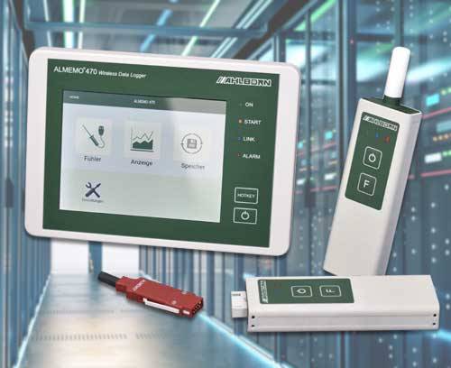
With the Almemo 470 wireless data logger by Ahlborn Mess- und Regelungstechnik, you can wirelessly measure climate parameters such as temperature or atmospheric humidity. A flexible connection technology for digital sensors allows the adaptation of a large number of different sensors for measuring different variables.
Application wireless data logger
Wireless network access point
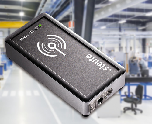
At field level, the sWave.NET wireless network by steute Schaltgeräte GmbH & Co. KG facilitates variable communication between wireless switching devices and access points, which function in a similar manner to a router. They receive signals from wireless switching devices, bundle them and then transmit them, e.g. by Ethernet or WiFi, to one or more application servers. The access points are installed across the transmission range and communicate with the wireless switchgear.
Application wireless network access point
Smart TAG

The conbee Smart TAG is based on the Bluetooth 4.x specification with a range of up to 150 m. The fully configurable TAG has an authentication function using out-of-band or SecureSimple pairing, is forgery-proof and has a motion sensor that is capable of detecting manipulation attempts. Status data are transmitted at dynamically adaptable transmission intervals in advertisement packets that provide information about the object to be tracked. The intelligent TAG cyclically reports its identification number, temperature and movement data as well as battery status and optionally also its position.
Application Smart TAG
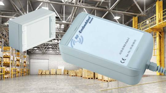
Robust UHF reader
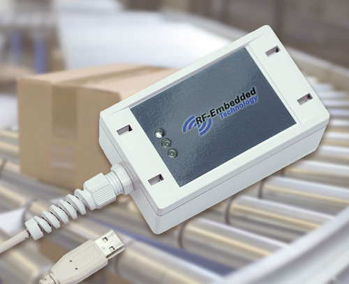
RF-Embedded GmbH has developed an RFID reader for the passive ultra high frequency (UHF) radio range, which generates an energy field from electromagnetic waves. As soon as a passive UHF transponder enters the energy field, it sends the content of its memory to the relevant RFID reader.
Application robust UHF reader
We have now drawn up a list of all enclosures that are suitable for the use of smart sensors under a separate heading. Now you can find a suitable sensor enclosure even more quickly.
Overview IIoT/Sensor Enclosures >>
To ensure that the standard enclosures also meet individual customer requirements in terms of company colour, visual adaptation to the usage environment, company logo, the electronic components and cables etc., we offer a wide range of services: painting, printing, EMC aluminium vapour plating as protection from stray radiation, cutouts/openings, for example for USB/SPI/I2C/LAN connectors or control buttons. In industrial enclosures with high IP classes, the use of special pressure compensation elements is a big advantage. A partial vacuum may be created inside sealed enclosures if there is a change of temperature. Moisture and dirt particles may be sucked in, damaging the sensitive electronics. These OKW pressure compensation elements can counteract this, since they allow an especially high air flow. At the same time the innovative design provides reliable protection against dirt and, if required, is absolutely waterproof up to a pressure of 6 bar.
#Enclosres#enclosure#plastic enclosure#plastic enclosures#okw#OKW Gehäusesysteme#OKW Gehäuse#OKW Enclosures#OKW Enclosure#IoT#IIot#iiot solution#smart factory#smart fabrics#smart industry#industry 4.0#sensor#sensoric#sensor enclosure#IoT enclosures#sensor enclosures#internet of things#industrial internet of things
2 notes
·
View notes
Text

AXI DMA Scatter Gather
Looking to take your digital projects to the next level? Look no further than our amazing Digital Blocks! Say goodbye to the hassle of manual data transfers and hello to the power of AXI DMA Scatter Gather, AXI Stream DMA, and i3C Basic IP. Featuring a user-friendly interface, these blocks are perfect for tech enthusiasts, engineers, and anyone in need of efficient data management. Whether you're a professional or a hobbyist, our Digital Blocks will help you achieve remarkable results. Experience the difference they can make in your projects today!
#i3c controller ip#display controller ip#lcd controller ip#axi dma scatter gather#i2c controller ip#i3c master#i2c master ip#espi ip#i2c slave ip#axi dma ip
0 notes
Text
Qorvo Introduces Multi Protocol SoC Controller for Low Power Wireless Applications
Qorvo has introduced a Multi-Protocol SoC Controller that supports Zigbee, Thread, and Bluetooth Low Energy standards. The QPG6100 is designed for connected lighting applications, switches, and other smart home end nodes. The controller is based on Qorvo’s ConcurrentConnect technology that enables Zigbee, Thread, and Bluetooth Low Energy to operate simultaneously in a single chip design.
The QPG6100 is also available in a development kit that provides a complete hardware and software solution for building Bluetooth Low Energy, Bluetooth Mesh, Zigbee, and Thread connected products with the QPG6100 IoT SoC. The kit enables quick time-to-market with a complete set of software, development boards, tools, and documentation.
Key features of QPG6100:
The QPG6100 from Qorvo is a Multi-Protocol SoC Controller that supports Zigbee, Thread, and Bluetooth Low Energy standards. It is based on ConcurrentConnect technology that allows concurrent listening and instantaneous switching between BLE and IEEE 802.15.4 protocols with no observable blind spots. The SoC has a Bluetooth data rate of 2 Mbit/s and consists of integrated baluns and RF filters. It is built using a patented IEEE 802.15.4 antenna diversity scheme that improves the reliable link budget by 8 dB resulting in approximately 70 % more coverage and range. In high-density networks, the SoC supports packet-in-packet resynchronization that improves communication reliability further. It requires a DC supply of 1.8-3.6 V and can be controlled via UART, SPI, I2C, I2S, USB 2.0, and PDM interfaces. The QPG6100 consists of enhanced security capabilities that ensure an inherent highly secure smart home solution with built-in support for secure boot and OTA software upgrades. The SoC is available in a QFN40 package that measures 6 x 6 mm and is ideal for low-power IoT end-node applications such as connected lighting, sensors, smart plugs, thermostats, and smart meters. Key benefits of QPG6100:
Fast time-to-market by leveraging reference applications as a basis for turn-key product solutions. Easy building of single SKU products with standard agnostic solutions that seamlessly integrate with a Bluetooth Low Energy Mesh and Zigbee network using Qorvo’s patented ConcurrentConnect technology. Interoperable with major Smart Home eco-systems: IKEA Home Smart, Philips Hue, Samsung SmartThings, and Amazon Alexa. QPG6100 supports Thread and Connected Home over IP applications through their respective open-source SW repositories. The development kit contains 3 development boards to quickly prototype applications. These boards combine QPG6100, peripherals, LEDs, buttons, power supply and a program/debug interface.
1 note
·
View note
Link
Parte 1: Introduzione
Guida a puntate su ESP8266
Cosa ci fa una guida su un hardware (si ESP8266 è un hardware) che non è Raspberry Pi, su un sito dedicato al Raspberry Pi? Bè, cominciate a leggere, e scoprirete che esistono molti più punti di contatto tra questi due oggetti, di quanto sospettavate. E sopratutto, non esiste (ancora) una documentazione chiara, completa e che parta da zero in italiano su questo oggetto, il che lo rende particolarmente ostico da affrontare per chi è alle prime armi con oggetti del genere. L’innumerevole varietà di versioni hardware e gli svariati firmware differenti, fanno perdere per strada il novellino in una marea di tutorial e guide in inglese, contraddittorie e totalmente differenti tra loro. E allora.. perchè non pensarci noi? Realizzeremo una serie di guide che ci porteranno a scoprire assieme questa piccola scheda, come programmarla, i vari firmware e gli usi pratici.
Ma di cosa stiamo parlando?
L’ ESP8266 si tratta si un SoC (System on Chip) prodotto dalla Cinese Espressif, contiene un microcontrollore, un modulo WiFi con stack TCP-IP completo. Sopratutto, ha un basso costo.
Ok, cosa è un microcontrollore?
Senza divagare troppo nel tecnico, possiamo dire che un microcontrollore (MCU), a differenza di un microprocessore (CPU) è meno raffinato, meno general purpose, più specializzato in un solo compito. Però questo consente di avere più componenti integrate (il processore, la memoria permanente, la memoria volatile e i canali di I/O), il che gli consente di funzionare con pochissimi (a volte nessun) componente esterno, mentre un microprocessore richiede una intera scheda madre e unità esterne, memorie, periferiche. Nei microcontrollori il programma da eseguire viene memorizzato direttamente nella ROM, assieme al firmware. Quindi non è in grado (non necessita) di un sistema operativo, con i relativi vantaggi/svantaggi che questo comporta. Tutto questo li rende molto economici quindi preferiti nelle applicazioni specifiche (calcolatrici, centraline di auto, modem, antifurti, elettrodomestici ecc ecc).
Storia
I microcontrollori esistono di ogni specie e versione, e fino a poco tempo fa non esisteva una configurazione standardizzata, e spesso i maker si creavano da soli la scheda con l’elettronica di contorno utile al loro funzionamento. Questo produceva un hardware diverso per ognuno. Proprio per questo nacque Arduino, che creava una scheda Open Hardware standard con microcontrollore Atmel, e fu un gran successo. Poi nacque l’ESP8266, e il WiFi integrato è stata la sua arma vincente per distinguersi. Vista proprio l’estrema economicità, produttori di terze parti hanno incominciato a commercializzare piccoli moduli che montavano ESP8266, ottenendo subito (verso il 2014) un grande successo presso le comunità dei maker. E’ un SoC pensato per la produzione industriale (piccolo, i pin non hanno un passo standard, sono pensati per il montaggio SMD) quindi per usarlo a livello hobbystico più facilmente, è indispensabile averlo montato su una scheda con elettronica di contorno più o meno completa.
Versioni di ESP8266
Questo ha generato una marea di versioni in commercio differenti, di queste schedine. Le varianti più diffuse sono quelle prodotte da AI-Thinker, nominate ESP-01 , ESP-02, fino a ESP-14, ma ne esistono diverse di altri produttori, più o meno equivalenti. Si differenziano tra loro per le caratteristiche costruttive: il tipo di antenna del WiFi, la certificazione FCC o meno, la quantità di memoria, la presenza o meno di adattatori usb/seriali a bordo, il numero di Pin attivi. I prezzi sono irrisori: se comprate in Cina si va da 1,5 Euro per ESP-01 alle 3 Euro scarse per la scheda di sviluppo più completa con ESP-12E, ma i tempi di consegna sono oltre il mese (più vicino ai 60 giorni); in Italia, fate più o meno il doppio dei prezzi, ma potete comprare da Amazon.
GPIO
Si, l’ESP2866 ha dei pin liberi, programmabili dall’utente finale. un vero e proprio GPIO, e qui cominciano a notarsi le somiglianze con Raspberry Pi. Su questi pin sono disponibili I2C, SPI, UART, diversi pin ingressi/uscite digitali programmabili, e un ingresso analogico con ADC a 10 bit.
Caratteristiche
RISC CPU a 32-bit: Tensilica Xtensa LX106 funzionante a 80 MHz*
4Kb di memoria RAM per le istruzioni e 96Kb di memoria RAM per i dati
stack TCP/IP e la possibilità di collegarsi alle reti wifi b/g/n
supporto per un Flash RAM esterna da 512Kb a 4Mb a seconda della versione, in cui viene memorizzato il programma
16 GPIO (anche se non su tutti i moduli sono utilizzabili tutti e 16)
UART / I2C / I2S/ SPI / 1 modulo ADC a 10bit
* su alcune versioni, overcloccate, la CPU può funzionare a 160Mhz e la Flash RAM a 80Mhz (invece di 40)
Confusi? Non è ancora finita: per ogni versione Hardware, è possibile montare svariate tipologie di firmware completamente differenti, che cambiano in toto il modo in cui viene gestita la scheda e il linguaggio che useremo per comunicare con essa o per programmarla:
Firmware
Infatti, oltre al firmware di fabbrica di Espressif che utilizza i comandi AT per comunicare con il chip, sono stati sviluppati altri firmware alternativi che permettono di sfruttare molto meglio le potenzialità di questo piccolo gioiello tecnologico: Eccone alcuni, tra quelli Open Source:
NodeMCU: firmware basato sul linguaggio Lua
Arduino: firmware basato su C++. permette di programmare l’ESP8266 e la componente WiFi come fossero un Arduino. Disponibile su GitHub.
MicroPython: un port di MicroPython (una versione di Python per microcontrollori).
ESP8266 BASIC: un Basic Open Source adattato per l’IoT (Internet of Things).
Zbasic for ESP8266: Un sottoinsieme del diffuso Visual basic 6 di Microsoft, adattato a linguaggio per i microcontrollori della serie ZX e per l’ESP8266.
Mongoose Firmware: un firmware open source con servizio cloud gratuito
Open RTOS
ok, ma alla fine, che ci faccio?
L’ESP8266 può essere utilizzato in almeno in due modalità principali: come scheda a sé stante, o come accessorio per il nostro Raspberry. Vediamo prima quest’ultima: può essere configurato per fare da bridge USB/seriale – Wifi, per trasformare le connessioni seriali o USB in connessioni Wifi senza fili in modo da far acquisire la funzionalità wireless a qualche dispositivo che già usate con Raspberry Pi (controller, centraline varie, apparecchiature industriali..). Oppure è perfetto per raccogliere i dati di diversi sensori e trasferirli via Wifi al Raspberry, o viceversa fare da Hub wireless per diversi attuatori (relè, motori..). Uso “stand-alone”: avete sviluppato e ottimizato il vostro progetto di physical computing con Raspberry? Bene, perchè sprecare così il Raspberry Pi? Probabilmente, nella maggior parte dei casi, quel compito lo può svolgere anche ESP8266, basterà adattare il vostro programma, e con Python potrebbe essere anche meno complicato che portare pace e armonia nel mondo. Implementazioni quali quelle che leggono sensori, comandano relè e LED, ma anche che pilotano display o gestiscono interfacce web, possono tranquillamente essere portate su ESP2866, con evidente risparmio di denaro e con una realizzazione meno delicata e più adatta all’ uso embedded (non c’è la SD, il programma andrà a risiedere nella ROM) e più compatta. Le dimensioni assai contenute e la capacità di connettersi via WiFi, rendono questa scheda perfetta per le applicazioni di domotica: facile da integrare negli impianti esistenti essendo poco ingombrante e non richiedendo cablaggi per la rete ethernet cablata. Per gli stessi motivi, è perfetta anche per le applicazioni nel campo dell’IoT (Internet of Things). Inoltre, è possibile comandarla via smartphone con apposite app.
Come vedete, la carne al fuoco è davvero tanta.
Fermi! Non correte subito a comprarne un esemplare, invogliati dal prezzo allettante! Nella prossima puntata, vedremo le versioni hardware più diffuse, come farle funzionare, e qualche suggerimento su quale modello scegliere per cominciare a sperimentare subito questo nuovo mondo. Seguiteci!
4 notes
·
View notes
Text
Trilithic Seeker Port Devices Driver Download

Trilithic Seeker Port Devices Driver Download Pc
Trilithic Seeker Port Devices Driver Download Free
Trilithic Seeker Manual
The Seeker MCA III offers high-performance GPS location recording and documentation when monitoring only the aeronautical bands with existing Seeker leakage detectors or monitoring both the aeronautical and near-LTE bands with the Seeker D leakage detector. This device also allows you to daisy chain the mobile mounts of the Seeker and Seeker D. HTDIR-driver.h (HiTechnic IR Seeker V2 driver ). IR Seeker I2C device address. Link the HTCS port number. Seeker Lite² Leakage Detector - Operation Manual 2 Trilithic Company Profile Trilithic is a privately held manufacturer founded in 1986 as an engineering and assembly company that built and designed customer-directed products for telecommunications, military and industrial customers. .ok, this line of questions should go in the help part of the forums as is not related to this UDF ( from 2007 ). Software is not magic, it runs on hardware. Having an idea of how the hardware works at a bit level, is important to have an idea of what is, or could be, going on with the stuff we plug in.
Trilithic, Inc. – Shareware –
Overview
Trilithic Seeker Setup is a Shareware software in the category Miscellaneous developed by Trilithic, Inc..
The latest version of Trilithic Seeker Setup is currently unknown. It was initially added to our database on 04/12/2013.
Trilithic Seeker Setup runs on the following operating systems: Windows.
Trilithic Seeker Setup has not been rated by our users yet.

Write a review for Trilithic Seeker Setup!
02/13/2021 SGP Baltie 3 3.0.71.121 02/13/2021 カスペルスキー VPN 21.2.16.590 02/13/2021 PlayGames клиент 1.0.9 02/13/2021 Command & Conquer Remastered Collection 1.153.11.25007 02/13/2021 Kate's Video Cutter (free) 6.317

02/10/2021 Adobe updates available 02/10/2021 Firefox 85.0.2 update fixes startup problem 02/09/2021 Microsoft Patchday February 2021 02/09/2021 Updates for Chromium-based browsers now available 02/08/2021 Find the best browser extensions to protect your privacy
» trilithic seeker setup v3.8x or later
» trilithic seeker setup software
» trilithic drivers
» trilithi seeker
» trilithic seeker d meter drivers
» seekerd trilithic software
» trilithic seeker setup v3.84
» seeker setup
» trilithic seeker driver
» trilithic seeker setup
Overview
SkyFi III is our WiFi-to-Serial adapter, designed for wireless telescope control. If you have a computer-controlled GoTo telescope, SkyFi III can use the WiFi capabilities built into your computer and your iOS or Android device to point your telescope in the sky. SkyFi III is the only WiFi device on the market specifically designed for telescope control, and it now includes a built-in rechargeable lithium ion battery for up to 12 hours of field use!

SkyFi III includes both USB and serial ports - this means that it can control the latest USB-only telescopes from Meade as well as other telescopes with RS-232 serial interfaces.
What's included
SkyFi III is very compact, barely larger than an iPhone. It can be easily attached to your telescope's mount or tripod; a Velcro belt is included for that purpose.
SkyFi III has a micro USB connector for external power. It can be powered or charged from a standard 5V USB port on your computer. The package includes a micro USB power adapter (North American orders only) that accepts worldwide AC current (100-240V, 50-60 Hz). You can also power SkyFi III from a car battery using a 'cigarette lighter' micro USB adapter (not included).
How it works
Once powered on, SkyFi III creates its own 802.11 wireless network. By default, this is an open wireless network called 'SkyFi', but you can rename and secure it later on. Join this network from your mobile device, laptop, or other computer, and - voila! - you're ready to use SkyFi III. As long as your computer or mobile device gets its IP address by DHCP, no additional network configuration is required.
Use your existing telescope serial cable and plug directly into SkyFi III - you don't need to buy (or build!) another. If you don't already have one for your telescope, see here for our selection.
Finally, you'll also need a telescope control application running on your computer or mobile device. SkyFi III works seamlessly with our SkySafari apps for iOS and Android devices, our SkySafari software running on macOS, and our Starry Night software on Mac and via Virtual Serial Port on Windows.
Trilithic Seeker Port Devices Driver Download Pc
QuickStart Guide
Get the SkyFi 3 QuickStart Guide here
Firmware
Please update the firmware in your SkyFi III. The latest firmware (1.3.4) can be downloaded here

Download the file to your desktop computer.
Turn the SkyFi 3 on and join its network from the desktop computer.
Go to http://10.0.00.1 in a browser.
Click the Firmware tab in the SkyFi configuration page and follow the instructions for updating the firmware.
If further assistance is required regarding the firmware please create a new post in the SkySafari Community Forums
Trilithic Seeker Port Devices Driver Download Free
Telescope Compatibility
Trilithic Seeker Manual
SkyFi III can wirelessly enable almost any telescope with a standard USB or RS-232 serial interface. All Models that are expected to work are listed below, but models that have not as yet been tested and confirmed to work with SkyFi III are marked with a double asterisk ** If you confirm any of these models please let us know.
0 notes
Text
Explore the Features of ESP8266 NodeMcu WiFi Development Board
The NodeMCU is an ESP8266 WiFi based microcontroller board that helped overcome some of the difficulties associated with several versions of boards based on the ESP8266 WiFi module/chips from Espressif. As the popularity of Arduino boards increased, the demand for boards which comes embedded with some of the add-ons used with the Arduino increased. One of the most popular add-ons were the WiFi modules which are used to connect Arduino boards to the internet.
Several boards were released by different manufacturers which used the Arduino form factor and had onboard WiFi module, but none of these boards became as popular as the NodeMCU. Today, we will be exploring how to use the ESP8266 NodeMCU board in projects and especially how to easily program the board using the Arduino IDE. The NodeMCU is an ESP8266 WiFi based microcontroller board that helped overcome some of the difficulties associated with several versions of boards based on the ESP8266 WiFi module/chips from Espressif.
ESP8266 NodeMcu WiFi Development Board Features:-
It is based on ESP8266, integates GPIO, PWM, IIC, 1-Wire and ADC all in one board.
Power your developement in the fastest way combinating with NodeMCU Firmware!
USB-TTL included, plug&play
10 GPIO, every GPIO can be PWM, I2C, 1-wire
Open source IoT Platform
Easily Programmable
Low cost & Simple to Implement
WI-FI enabled
ESP8266 NodeMcu WiFi Development Board Applications:-
Home Appliances
Home Automation
Smart Plug and lights
Mesh Network
Industrial Wireless Control
Baby Monitors
IP Cameras
Sensor Networks
Wearable Electronics
To know more about all latest Products of ESP8266 WIFI Modules you can visit at www.campuscomponent.com
0 notes
Text
QR Code Based Bus Name Announcement System in Bus Stops | ESP32CAM QR Code Recognition
youtube
ESP32 QR Code Recognition Camera | QR Code Based Bus Name Announcement System in Bus Stops ****************************************************************** If You Want To Purchase the Full Project or Software Code Mail Us: [email protected] Title Name Along With You-Tube Video Link Project Changes also Made according to Student Requirements http://svsembedded.com/ è https://www.svskits.in/ M1: +91 9491535690 è M2: +91 7842358459 ****************************************************************** 1. QR Code Bus Name Announcement System in Bus Stops ESP32 cam, 2. ESP32CAM QR Code Reader | ESP32-CAM-QR Code, 3. QR Code Based Door Lock System using ESP32-CAM, 4. ESP32CAM QR Code Scanner, 5. ESPino32(ESP32) + OV2640 Camera Read QR Code, 6. ESP32-CAM Video Streaming and Face Recognition, 7. How to use ESP32 Camera Module for Video Streaming, 8. Bus Detection Device for the Blind Using QR Code, 9. Bus detection device for the blind using RFID application, 10. Use of NFC and QR code identification in an electronic ticket, 11. digital bus pass using qr-code, 12. Bus Detection System for Blind People to Track The device, 13. Tags That Help Visually Impaired Transit Riders, 14. Making Shopping Easy for People with Visual Impairment, 15. bus detection for blind using rfid ppt, 16. bus identification system for visually impaired person project, 17. Bus Detection Device for the Blind Using RFID, 18. RFID Based Bus Name Announcement System in Bus Stops, 19. rfid based assistance for bus travel for the blind, 20. Bus detection for blind people using RF transceiver, 21. DIGITAL BUS PASS USING QR-CODE, 22. How to use ESP32 Camera Module for Video Streaming, 23. Scanning QR Code using esp32 cam - Arduino Forum, 24. ESP32CAM QR Code Reader | ESP32-CAM-QR Code, 25. ESP32-CAM Video Streaming and Face Recognition, 26. ESP32 CAM Arduino Kits Monitor Snapshot Face Detection, 27. Track Everything, Everywhere With An IoT Barcode Scanner, 28. ESP32-CAM | ESP32 Camera Module with Face Recognition, 29. Unlock a Door With Face Recognition Using ESP32 Camera, 30. ESP32 CAM for Arduino Kits Monitor Snapshot Face Detection, 31. Real time QR Code recognition for Arduino robot navigation, 32. Face recognition-based real-time system for surveillance, 33. GPS Enabled Automatic Bus stop Announcement system on Kannur Bus, 34. APP - Next Stop Announcement System for Buses, 35. ESP32 CAM Surveillance Car | SPY Camera Car, 36. ESP32 Cam based Motion Triggered Image Capturing Device, 37. ESP32-Cam Quickstart with Arduino Code, 38. Blynk Live Video Streaming using ESP32 cam/ESP eye, 39. ESP32-CAM Video Streaming Camera Over WiFi , 40. Security Camera System for Home - IP (ESP32 - OV2640), 41. Arduino-Based Gauss Meter, 42. Weather Logger, 43. Soccer Robot, 44. Drawtiming Diagrams in Linux, 45. Web-Based Water-Level Monitor and Pump Controller, 46. Accessing GPIOs using SYSfs interface of Linux, 47. GPS on Raspberry Pi, 48. Serial-Port Monitor in Visual Basic, 49. Energy Meter, 50. Colour-Sensing Robot with MATLAB, 51. Part 1 of 5: Designing with FPGAs: I2C Master Controller, 52. Part 2 of 5: Designing with FPGAs: Interfacing an LCD, 53. Thermoelectric Refrigerator, 54. Guiding Visually Challenged Using Raspberry Pi, 55. Real-Time Clock with Temperature Logger, 56. Safety Timer for Home Appliances, 57. Solar-Powered Home Lighting System, 58. Part 3 of 5: Designing with FPGAs: An RS232 UART Controller, 59. Arduino-Controlled Namaste Greeting Robot, 60. Resistor Value Calculation Standalone Application with MATLAB, 61. Serial LCD Module, 62. Raspberry Pi GPIO Access Using C, 63. Live Telecasting on Your Web, 64. Part 4 of 5: Designing with FPGAs: Clock Management, 65. Designing 8-to-1 Multiplexer Using LabVIEW, 66. RF-Controlled Aircraft, 67. Programmable Interval Timer for Live Shows, 68. Car-Reversing Audio-Visual Alarm, 69. Power Factor Corrector, 70. Part 5 of 5: Designing with FPGAs: FPGA-Embedded Processors, 71. Web-Based Device Controller With Arduino Board, 72. Interfacing Dot Matrix LED with Raspberry Pi, 73. Quiz Game Controller, 74. Arduino-Based FM Receiver, 75. Designing Dual-Priority Encoder Using LabView, 76. C++ Implementation of Digital FIR Filters Using Blackman Window, 77. Sequential Tilt-Motion Lock, 78. Oscilloscope as an Image Viewer, 79. Use of I²C for Extension of GPIOs, 80. Understanding Digital Camera Histograms Using MATLAB, 81. Building Image Processing Embedded Systems Using Python, 82. Face Counter Using MATLAB, 83. XBee-Controlled Aircraft, 84. RFID Based Access Control Using Arduino, 85. Weather-Forecast Monitoring System, 86. Software to Help You Select Inverter for Your Home, 87. Colour Segmentation Using MATLAB, 88. Automated Plants Watering System, 89. LED Scrolling Display,
0 notes
Text

AXI DMA IP
The AXI DMA IP provides scatter-gather support, which allows the user to specify a list of contiguous buffers and have them distributed across the AXI bus. AXI DMA IP can be configured to handle many tasks concurrently and provide a boost to system performance. Get more details about us from https://www.digitalblocks.com/dma/
#i3c controller ip#display controller ip#lcd controller ip#axi dma scatter gather#i2c controller ip#i2c master ip#espi ip#i3c master#i2c slave ip#axi dma ip
0 notes