#i2c protocol tutorial
Explore tagged Tumblr posts
Visit Tumblr Blog
Explore Tumblr blogs with no restrictions, modern design and the best experience.
Last Seen Tumblr Blogs


Fun Fact
US Tumblr user growth rate is estimated to slow down to 4.1%.
Text
How i2C protocol works....
#mobicationhub #mobicationhub9509959090 #Protocol #reelsfypシ #i2c #institute #phonerepair #mobilerepaircoursejaipur #mobilerepairing #working #1monthcours #laptop
#i2c protocol#i2c protocol tutorial#protocol#spi protocol#communication protocols#i2c protocol vs spi protocol#communication protocol#how i2c protocol works#i2c protocol - inter integrated circuit protocol#i2c communication protocol#i2c protocol working#serial communication protocol#inter integrated circuit protocol#inter-integrated circuit protocol#i2c bus protocol#i3c protocol#what is i2c protocol#basics of i2c protocol#spi protocol tutorial
0 notes
Text
Emertxe Embedded Systems Online Course – A Gateway to a Thriving Career

Are you looking to kickstart your career in embedded systems but don't have the time to attend traditional classroom-based courses? Emertxe's Embedded Systems Online Course offers the perfect solution to gain in-depth knowledge and practical experience in this rapidly growing field from the comfort of your home.
Why Choose Emertxe’s Embedded Systems Online Course?
Emertxe is a leading provider of embedded systems training, offering specialized online courses designed to bridge the gap between academic knowledge and industry requirements. With its embedded systems online program, you can gain expertise in key areas such as microcontrollers, real-time operating systems (RTOS), device drivers, communication protocols, and much more.
Here’s why Emertxe’s embedded systems online course stands out:
1. Industry-Recognized Curriculum
Emertxe’s course content is developed in collaboration with industry experts and aligned with the latest trends and technologies in embedded systems. The online embedded systems program includes everything from the basics to advanced topics, ensuring that you are well-prepared for industry challenges.
2. Hands-on Learning Experience
Emertxe’s online embedded systems course focuses heavily on practical learning. You will work on real-time projects, assignments, and simulations that help solidify your understanding and improve your problem-solving skills. Emertxe’s online platform makes it easy to access tutorials, lab sessions, and code examples anytime, anywhere.
3. Experienced Trainers
Learn from highly qualified instructors who have hands-on experience in embedded systems development. Emertxe’s trainers are industry veterans who share their insights and guide you through the complexities of embedded system design and implementation.
4. Flexible Learning Pace
One of the key advantages of the Emertxe embedded systems online course is the flexibility it offers. You can learn at your own pace, revisit lessons whenever needed, and balance your studies with personal and professional commitments.
5. Job Placement Assistance
Emertxe provides placement assistance to its students. With its strong industry connections and a network of partner companies, Emertxe helps students get placed in top tech companies. Graduates of the online embedded systems program are highly sought after for roles such as Embedded Engineer, Firmware Developer, and Hardware Design Engineer.
Key Topics Covered in Emertxe’s Embedded Systems Online Course
Introduction to Embedded Systems: Learn the fundamentals of embedded systems, including their applications in various industries like automotive, consumer electronics, healthcare, and more.
Microcontroller Programming: Get hands-on experience in programming microcontrollers like ARM and AVR to build embedded solutions.
Real-Time Operating Systems (RTOS): Dive into RTOS concepts such as task scheduling, inter-process communication, and memory management to design responsive embedded systems.
Embedded C and C++ Programming: Master the core languages used in embedded systems programming and develop efficient, resource-constrained applications.
Device Drivers and Communication Protocols: Learn to develop device drivers and implement protocols like UART, SPI, I2C, and CAN to ensure seamless communication between components in embedded systems.
Embedded Linux: Explore the power of Linux in embedded systems and understand how to work with Linux kernel, drivers, and file systems.
Career Opportunities After Completing Emertxe’s Embedded Systems Online Course
Graduating from Emertxe’s embedded systems online program opens the doors to a wide range of career opportunities. The demand for skilled embedded systems professionals is soaring in sectors like automotive, aerospace, telecommunications, and consumer electronics. Emertxe’s curriculum equips you with the expertise needed to take on roles such as:
Embedded Systems Engineer
Firmware Developer
Embedded Software Developer
Hardware Engineer
Embedded Systems Consultant
How to Enroll in Emertxe’s Embedded Systems Online Course
Enrolling in the Emertxe embedded systems online course is simple. Visit the Emertxe website, select the online course option, and follow the easy steps to complete your registration. With flexible payment plans and a dedicated support team, Emertxe ensures that the entire process is smooth and hassle-free.
Final Thoughts
Emertxe's embedded systems online course is the perfect way to build a solid foundation in embedded systems while balancing your existing commitments. With a comprehensive curriculum, hands-on projects, and job placement assistance, Emertxe ensures that you are ready to take on exciting career opportunities in embedded systems development.
Ready to kickstart your career in embedded systems? Visit Emertxe Embedded Systems Online Course and enroll today!
0 notes
Text

Introducing the latest version of the NodeMcu ESP8266 CH340 Module – a cutting-edge, budget-friendly WiFi technology. This advanced board utilizes modern, high-level LUA based technology and offers an all-in-one design, making it incredibly easy to integrate into your current Arduino projects or any development board with available I/O pins.
Utilizing modern Internet development tools, like Node.js, can effectively accelerate the implementation of your ideas with the assistance of the built-in API provided by NodeMCU. Based on ESP8266 technology, NodeMCU harnesses a wealth of online resources to further enhance its capabilities.
The NodeMCU ESP8266 CH340 Module is equipped with ESP-12 based serial WiFi integration, allowing for easy access to GPIO, PWM, ADC, I2C, and 1-WIRE resources. It also features a built-in USB-TTL serial using the dependable CH340 for superior stability on all compatible platforms. Additionally, this wifi-module is one of the most cost-effective options currently available in the market. Its latest version is known as V3 or Version3. In this tutorial, we will provide instructions to connect any version of ESP8266 NodeMcu (V1, V2, or V3).
Hardware IO similar to Arduino – An advanced API for easily configuring and manipulating hardware, reducing repetitive tasks. Write code in Lua script, just like with Arduino but in a more interactive manner.
The Event-driven API for network applications in Nodejs style enables developers to easily write code for a compact 5mm5mm sized MCU. This greatly accelerates the development process for IOT applications.
The ESP8266 Development Kit combines GPIO, PWM, IIC, 1-Wire, and ADC on a single board. By using the NodeMCU Firmware, it allows for quick and efficient development.
The NodeMcu is a useful tool for creating IoT prototypes. It is an open-source firmware and development kit that allows you to write Lua scripts with ease. This Development Kit is built on the ESP8266 platform and includes integrated features such as GPIO, PWM, IIC, 1-Wire, and ADC, all conveniently housed on one board.
Attributes of NodeMcu ESP8266 CH340 Module are:
Utilizes CH340G in place of CP2102.
The standard for wireless technology, specifically 802.11 b/g/n, eliminates the need for cables.
The WiFi operates at 2.4GHz and offers WPA/WPA2 security mode.
Provide assistance for the three available operating modes: STA, AP, and STA AP.
The TCP/IP protocol stack is integrated to facilitate the handling of multiple connections from TCP Clients (up to a maximum of 5).
The data communication interface supports UART and GPIO.
OTA, or remote firmware upgrade, is a quick and efficient way to update your device’s firmware without having to physically connect it to another device.
Assist the enhancement of Smart Link Smart Networking.
The IO Pin is an integral part of ESP8266.
There is no need to download the reset function.
An excellent toolkit for enhancing ESP8266 capabilities.
The WI-FI with the most affordable price.
For hardware IO compatible with Arduino.
Maximize efficiency in developing your IOT applications.
This product boasts a range of impressive features, including its open-source capability, interactivity, programmability, affordability, user-friendly design, intelligent functions, and WI-FI connectivity.
The integrated WI-FI MCU ESP8266 development kit offers effortless prototyping capabilities.
Our platform offers the most cost-effective solution for developing IoT applications.
NodeMCU ESP8266 CH340 Module features a built-in USB-TTL serial port, equipped with the highly dependable industrial-grade CH340G chip, ensuring unrivaled stability across all compatible platforms.
The Advanced API offers hardware IO capabilities that greatly minimize the need for repetitive tasks involved in setting up and managing hardware.
The network application’s event-driven API enables developers to write Nodejs-style code for a compact 5mm*5mm MCU.
0 notes
Text
Mastering Embedded Systems: A Comprehensive Online Course Overview
Embarking on the journey to master embedded systems can open doors to exciting career opportunities and allow you to contribute to innovative technologies shaping our world. With the convenience and flexibility of online learning, you can now access comprehensive courses that delve deep into the intricacies of embedded systems. In this blog, we'll provide an overview of what to expect from a comprehensive online course in embedded systems, guiding you through the path to mastering this dynamic field.
Understanding Embedded Systems
Before diving into the specifics of an online course, let's briefly recap what embedded systems are. Embedded systems are specialized computing systems designed to perform specific tasks within larger systems or devices. They are ubiquitous in modern technology, powering everything from smartphones and smart appliances to automobiles and industrial machinery.
The Importance of a Comprehensive Course
A comprehensive online course in embedded systems goes beyond surface-level knowledge, providing you with a deep understanding of the underlying principles and practical skills needed to excel in this field. Such a course covers a wide range of topics, including:
Embedded Hardware Design: Understanding the architecture and components of embedded systems, including microcontrollers, sensors, and actuators.
Microcontroller Programming: Learning programming languages such as C and assembly language to write code for embedded systems.
Real-Time Operating Systems (RTOS): Exploring the concepts of multitasking, scheduling, and resource management in real-time embedded systems.
Embedded Software Development: Developing software applications for embedded systems, including device drivers, firmware, and middleware.
Communication Protocols: Understanding protocols such as UART, SPI, I2C, Ethernet, and CAN bus for inter-device communication.
Embedded System Debugging and Testing: Learning techniques and tools for debugging, testing, and troubleshooting embedded systems.
Course Format and Delivery
A comprehensive online course in embedded systems typically offers a variety of learning resources and formats to cater to different learning styles. These may include:
Video Lectures: Engaging video lectures presented by experienced instructors, covering key concepts and practical demonstrations.
Interactive Tutorials: Hands-on tutorials and exercises to reinforce learning and apply theoretical concepts to real-world scenarios.
Practical Projects: Opportunities to work on real-world projects, designing and implementing embedded systems solutions from start to finish.
Quizzes and Assessments: Regular quizzes and assessments to gauge your understanding of the material and track your progress.
Discussion Forums: Online forums for asking questions, sharing insights, and collaborating with fellow students and instructors.
Instructor Expertise and Support
One of the key factors that distinguish a comprehensive online course is the expertise and support provided by the instructors. Look for courses taught by experienced professionals with a deep understanding of embedded systems and relevant industry experience. Instructors should be accessible and responsive, providing guidance and support throughout your learning journey.
Student Success and Testimonials
Before enrolling in an online course, take the time to research student success stories and testimonials. Look for reviews and testimonials from past students who have completed the course and achieved success in their careers. Positive feedback and success stories can provide valuable insights into the quality and effectiveness of the course.
Conclusion
Mastering embedded systems requires dedication, commitment, and access to comprehensive learning resources. With a comprehensive embedded systems course online, you can gain the knowledge, skills, and confidence needed to excel in this dynamic field. By choosing a course that covers a wide range of topics, offers diverse learning formats, is taught by experienced instructors, and has a track record of student success, you'll be well on your way to mastering embedded systems and unlocking endless possibilities in your career.
0 notes
Note
What's a good starting point for learning this stuff? Most of my computer knowledge is being able to assemble the parts together, doing network and and system diagnostics, and just fiddling with OSes. (And the one time I used Backtrack + Reaver to hack my friend's wifi lol.) But Idk how to write code (I've tried tutorials but they never seem to stick.) or figure out how the actual circuitry itself works.
That actually is how many people get started.
As for writing code? I was taught how in school. There are many different approaches here, from picking it up through python on a linux command line environment, to playing with BASIC on a 8-bit microcomputer from the 1980s, to messing with C. There really isn’t one right answer, and I’m sure my followers have a variety of suggestions for how best to approach that.
Circuitry... if you haven’t figured it out by now, I approach this stuff from a vintage computer angle, which ends up having a similar approach to a microcontroller if you separated the chip out into the various components within: CPU, RAM, ROM, graphics, serial/parallel I/O controllers, etc. This user port on a C64 can feel similar to the digital I/O on an arduino for example. There was a time when a Radio Shack 100-in-One style kit would be a great answer to this, but times have changed, and most people don’t build analog circuits from scratch any more. I still do but that’s just how I roll.
We live in an era where arduinos are incredibly inexpensive, and provide a mix between a C-like language and simple circuitry where you can learn the hardware and software aspects hand in hand. Plus, you can learn the newer device control protocols beyond just serial, like I2C and SPI, and really put some cool stuff together that ends up being practical with not all that much effort as it used to require. Not to mention, once you find yourself restrained by the limitations of the arduino IDE, you can always leave it behind for higher performance options that grant you greater fine control over your microcontroller. Then Parallax Propellers, ARM Cortex M0′s, ESP32′s, etc. all become options depending on the type of performance you need to achieve.
I hope that answers your question in a helpful way.
14 notes
·
View notes
Text
In Tinkercad circuits, choose sensor substitutes.

Tinkercad Circuits has a small library of frequently used electronic parts by design. Beginners may easily explore the complexities of the electrical world without feeling overwhelmed thanks to this curation. The drawback is that you can't build an identical replica of your circuit in the simulator if you're looking for a particularly specific part number or version of a sensor that isn't there in the parts drawer.
Fortunately for all of us, there's usually a solution to represent your missing component by using a similar one instead. A few major groups of sensors contain many similar sensors. You can choose an appropriate replacement for your Tinkercad Circuit with the aid of this tutorial.
Digital sensors

As they are activated, analogue sensors provide a changing voltage and resistance. Potentiometers are the most common sort of analogue sensor, but other more specialised varieties exist as well, such as flex sensors, photoresistors, microphones, some temperature sensors, force-sensitive resistors (pressure sensors), piezo components, and some IR distance sensors. Analogue inputs can be read using Arduino's analogRead() function or Tinkercad's "read analogue pin" block.
We advise using a potentiometer or TMP36 temperature sensor as an alternative in Tinkercad circuits if the analogue sensor you wish to use has three pins, as they both have three pins (power, ground, and signal). The TMP36 requires a regulated power supply voltage (2.7-5.5V), whereas a potentiometer is an only resistive sensor. This is an important distinction to make.
The only viable alternative in Tinkercad Circuits if your analogue sensor only has two pins is a two-pin photoresistor (the piezo element in Tinkercad Circuits can only be used as an output).
Electronic Sensors

High/low voltage signals and more complicated digital signals are the two primary categories of digital sensors.
Pushbuttons, switches, tilt ball sensors, magnetic reed switches, PIR motion sensors, and vibration switches are a few examples of sensors in this category. Try one of the many switches and pushbuttons available in Tinkercad Circuits, but also have a look at the tilt sensor and PIR motion sensor, whose simulations might more precisely resemble whatever digital sensor you are trying to replicate. Using digitalRead();, Arduino may read signals with high or low voltage. "Read digital pin" is the Tinkercad block for digital inputs. Launch the simulation below, then click on each sensor to see what happens:
The swap possibilities are more constrained for more sophisticated sensors that make use of data protocols like i2c. There isn't a component that can act as your i2c device, yet you might be able to use the extra library by putting it into your Arduino sketch.
Further Resources
When you make a substitution, we advise using the annotation tool to put notes on your circuit. Even though you couldn't illustrate the precise correct component, this can still aid in communicating the intent.
Don't overlook Tinkercad Circuits' starters, which can get you up and going with several fundamental sensors very quickly (in the components drawer).
Try out our beginner-level Arduino courses using Tinkercad Circuits to learn more about how to add sensors into your Arduino projects.
Send the team your requests for components, please! Although we deliberately limit the number of available components, we are constantly considering what we can add to make Tinkercad Circuits even better. Your criticism is a gift. I'm grateful.
1 note
·
View note
Text
Basic Understanding of MIPI I3C Protocol
Hello, and welcome to my blog! Today I’m going to share with you some insights on the MIPI I3C protocol, which is a new standard for interconnecting sensors and peripherals in mobile devices. MIPI I3C stands for Mobile Industry Processor Interface — Improved Inter-Integrated Circuit. It is a low-power, high-speed, bi-directional serial bus that supports multiple masters and slaves. It also offers advanced features such as dynamic address assignment, in-band interrupts, hot-join, and command modes. MIPI I3C is designed to be backward compatible with I2C, but with much higher performance and efficiency. It can achieve up to 12.5 Mbps data rate with only two wires: SCL (clock) and SDA (data). It can also support up to 12.7 devices per bus segment, compared to only 112 devices for I2C. MIPI I3C is ideal for connecting sensors such as accelerometers, gyroscopes, magnetometers, pressure sensors, proximity sensors, ambient light sensors, and more. It can also be used for other peripherals such as touch controllers, audio codecs, display controllers, and power management ICs. MIPI I3C is a versatile and powerful protocol that can simplify the design and integration of mobile devices.
If you are interested to understand more about the MIPI I3C Protocol, then you can go through the PiEmbSysTech MIPI I3C Protocol Tutorial Blog. If you have any questions or query, that you need to get answer or you have any idea to share it with the community, you can use Piest Forum.
0 notes
Text
Maker Cardarduino

Arduino Code Maker
Online Arduino Schematic Maker
Create Arduino
Just a quick walk through how to use the SD card module with Arduino. It is the same for Micro SD card modules. The Arduino official site provide a library for this purpose, and I will describe how I used this library and explain what each function does.
The SD card module communicates with the Arduino over the serial peripheral interface (SPI) communication protocol. It can be simply connected to the Arduino’s hardware SPI pins. LCD with I2C Module to the Arduino As the name implies, the LCD module communicates with Arduino through I2C communication. After a week of research, brainstorming and studying we ended up making, the SD-CARD (social distancing icard). The SD-CARD consists of an Arduino Nano which is connected with a buzzer, an ultrasonic sensor and 2 LEDs. The ultrasonic sensor calculates the distance between the person wearing it and people near him/her.
Buy the Arduino from: Banggood | Amazon
Buy SD Card Module from: Amazon | Banggood
I have not tested this library with all the SD card modules, but I think it should work for majority of them, unless you are told by the seller that you should use a different library.
The Library uses standard SPI interface for communication, which hasSPI buses, MISO, MOSI, SCK (CLK) and a chip select signal pin, CS.
(pic)
** MOSI – pin 11 ** MISO – pin 12 ** SCK (CLK) – pin 13 ** CS – pin 4
The default Arduino library for SD card is huge! With the example read/write sketch, when compiled it’s 13690 Bytes which is half of the available flash space on an Arduino pro mini!
So if you are tight in sketch space, it’s a good idea to find a smaller library. Depends on the SD cards you have and the format you want to use, you have these options.
FAT32 Format (larger than 2GB)
Adafruit SD (almost the same as Arduino SD, except a few optimization on SRAM memory)
FAT16 Format (smaller than 2GB)
I haven’t tested all of these libraries, so do your research and test them before using it. Here I will show you how to use the Arduino SD library.
The SD library comes with the Arduino IDE, so you don’t need to download it. It needs to be include at the beginning of the sketch.
Including `SD.h` automatically creates a global “SD” object which can be interacted within a similar manner to other standard global objects like “Serial”.
Read from SD card
First you need top open the file first.
It will return false if it fails to open the file, so check dataFile before using it. The “read” function reads the file line by line, so you will have to use a while loop, until it fail to reach the end of the file. Now you can write to the file using this.

Note that you need to close the file after finished reading it. Also, you can only open one file at a time, if you want to read the next file, you need to close the current file first.
Write to SD card
First you need to open the file you want to write to with “FILE_WRITE” parameter.
The “open” function takes two parameters, file location and mode (only required for “Write”, if missing by default it opens the file in Read-Only mode). It will return false if it fails to open the file, so check dataFile before using it. Now you can write to the file using this.
Note that you need to close the file after writing to it. Also, you can only open one file at a time, if you want to open the next file, you need to close the current file first.
Check if a File Exists
Create a Text File on SD Card
There isn’t a function for this purposes, but you can open a file with “FILE_WRITE” mode to create a file, if this file doesn’t exist.
Delete a File on SD card
List All the files on SD card
There isn’t a function for this in the library, but we can create a custom function to achieve this purpose. This function is from the example sketch in the Library. It prints the file directory to serial monitor.
Testing SD card or Get SD Card Information
Track ME is a 'small' GPS, SD Card, and GSM Shield controlled by an Arduino Mega.Call me and get my location.
Track ME
Arduino Code Maker
Project tutorial by Hugo Gomes
57,633 views
32 comments
94 respects
In this tutorial, you’ll learn how to use SD and micro SD cards with Arduino in a simple project to measure the environment temperature.
SD Card Module with Arduino: How to Read/Write Data
by ElectroPeak
104,338 views
12 comments
24 respects
This project describes of a low-cost GPS data logger for RC planes. In a previous project I described how to build a GPS data logger.
RC LOGGERSTATION - GPS Data Logger for RC Plane
Project tutorial by yvesmorele
5,044 views
2 comments
14 respects
Make your kid's battery-operated electric bike more fun with Arduino!
Electric Bike
Project tutorial by ifeghali
4,665 views
2 comments
13 respects
An Arduino based MP3 player with 30 levels of volume adjustment, 5 levels of EQ adjustment, and a pretty cool retro looking UI.
Arduino Retro Style MP3 Player!

Project tutorial by Neutrino
11,344 views
0 comments
23 respects
This project will play sound from Arduino and work the same as Google Assistant with limited commands. voice-controlled automation.
Talkative Automation || Audio from Arduino || HC-05 || Voice
Project tutorial by Vishalsoniindia
5,831 views
0 comments
9 respects
A small device that can be placed in a car's console to serve various functions such as temperature, time, date, etc.
Car Console Computer
Project showcase by Bie
4,761 views
0 comments
5 respects
Doorbell plays sound from microSD card and Arduino.
SD Card Doorbell
Project tutorial by Projecter
4,429 views
0 comments
10 respects
Connect Ultrasonic Ranger and MicroSD to Arduino, and program it to record the distance - Quick and Easy!
Measure Distance With Sonic Ranger And Record It On MicroSD
Project tutorial by Boian Mitov
4,263 views
0 comments
21 respects
Aim of this project is to improve the experience of the visually challenged, while making cashless transactions in public.
Online Arduino Schematic Maker
Payment Terminal for the Visually Challenged
Project tutorial by Paarth Arkadi
3,636 views
1 comment
8 respects
This project uses a micro SD card to store a text file and print it out to a 16x2 liquid crystal display.
Reading Text Files From an SD Card (Arduino)
Project tutorial by millerman4487
2,815 views
1 comment
4 respects
This is an Arduino base, preset keyboard emulation (HID-human interface device), with SD card file reader and AES 128 encryption.
Create Arduino
Arduino Programmed Keyboard Strikes
Project in progress by Sam
2,295 views
0 comments
1 respect
Retrieve data from speed and cadence sensor in a bike trainer. Display info in LCD screen and log in a SD Card
Bike trainer logger
by cimanes
913 views
0 comments
1 respect
0 notes
Text
Control FAN Speed and LIGHT using TV Remote
youtube
Control FAN and LIGHT using TV remote | Control of Lights + Fan using Wi-fi and Bluetooth | Arduino Based Home Automation using TV Remote | IR Remote Controlled Home Automation Project using Arduino | Smart Home Automation Using Arduino and Infrared Remote. ****************************************************************** If You Want To Purchase the Full Project or Software Code Mail Us: [email protected] Title Name Along With You-Tube Video Link Project Changes also Made according to Student Requirements http://svsembedded.com/ è https://www.svskits.in/ M1: +91 9491535690 è M2: +91 7842358459 ****************************************************************** 1. Control FAN and LIGHT using TV remote, 2. Control your LEDs with your TV remote - Arduino IR Tutorial, 3. Using IR Remote Controls with the Arduino, 4. HACKED: TV Remote becomes an RF Remote || nRF24L01, 5. Use Infrared sensor & IR Remote control on Arduino – Tutorial, 6. EEVblog - IR Remote Control Arduino Protocol Tutorial, 7. How to make voice control home automation system using Arduino, 8. Control your room lights and fan using TV remote, 9. How to make ir remote control home automation using Arduino multiple channel, 10. Infrared (IR) Remote control. Arduino, 11. Control your Infrared Devices from the Internet with IR Remote (Arduino / Raspberry Pi Compatible), 12. Control a Stepper Motor using an IR Remote and Arduino UNO – Tutorial, 13. Arduino Controlled using TV or IR Remote - TV/DVD Remote Decode, 14. Fast Hacks - Clone Infrared Signals with Arduino, 15. How to hack any IR Remote using Arduino, 16. Dish Antenna Position Controller Using TV Remote, 17. Control any Electronics with a TV Remote | Arduino IR Tutorial, 18. Arduino Controlling LEGO Power Functions Motor Part 2: IR Remote Control, 19. Arduino Home Automation: Control Your TV, Air Conditioner, Fan, etc. with an Infrared Transmitter, 20. How to Decode any IR remote |TV,DVD,AC any other, 21. Sinhala Arduino Tutorial 08 - IR Remote Controller (TV remote), 22. How to Control Arduino Robot Car with TV Remote Control | Infrared Remote IR, 23. Using IR Signals to Control TV, 24. ARDUINO: IR REMOTE CONTROL OF LEDS, 25. 5-min Tutorials: Arduino IR Remote & Receiver, 26. Remote Controlled AC Fan Regulator using Arduino, 27. Arduino - Control LED's with IR Remote Control, 28. Tutorial on Infrared sensor TSOP 1738 with Arduino | Connections & Coding, 29. ESP8266 As A WiFi Controlled Universal Remote, 30. Android Remote Control TV or other IR devices, 31. Arduino IR Remote Control Do it yourself, 32. Remote control Fan- IR remote control Circuit using IC 555 Timer, 33. Arduino Project: MP3 player with IR remote control DIY, 34. Apple Remote as a Universal Remote Control using Arduino [Anything Arduino], 35. Bluetooth & IR Remote - Elegoo Arduino Smart Robot Car Part 2, 36. How to Decode IR Remote Control Signals, 37. Using a VS1838B IR Sensor to Remotely Control an Arduino Project, 38. Arduino control LEDS with IR remote, 39. IR Remote Control For Home Appliances Using Arduino Multiple Channel, 40. Arduino turn off lights with TV remote - 120V relay, 41. App Inventor 2 - Arduino + Android Tv remote, 42. Fast Hacks -17 - Remote Control your Computer using Arduino, 43. [Basic]Arduino IR remote Control: Control LED using TV Remote, 44. TUTORIAL: How to Quickly Setup Infrared IR Remote Control Sensor with ESP32 - Arduino - ESP8266, 45. How to use Arduino as TV Remote Controller with Infrared, 46. Arduino IR Remote Control, 47. Controlling Servo motor with IR Remote using Arduino code, 48. Arduino Controlled Remote Door Opener using Servo Motor, 49. Control remote universal: Control to TV con Arduino, 50. Control LED with IR Remote Control + Arduino, 51. ESP 8266 NodeMCU RGB LED Strip controlled by a web server remote, 52. Make your own TV remote controlled car| Super easy Arduino tutorial, 53. IR Remote Control For Home Appliances Using Arduino Multiple Channel, 54. Magnetic Loop Antenna controlled by Arduino and infrared, 55. Home Automation With TV Remote in HINDI, 56. Tutorial: Controlling an Arduino with an Infrared (IR) Remote Control, 57. HOW TO MAKE A ARDUINO UNIVERSAL REMOTE CONTROLLER, 58. How to Control Your TV With an ARDUINO, 59. Using Infrared sensor & IR Remote control with an Arduino, 60. Home Automation using Arduino and IR Remote, 61. Arduino remote controlled camera mount – ir object tracking shield, 62. NEC Protocol IR remote control decoder using PIC16F877A CCS PIC C, 63. Bluetooth to IR TV Remote using Android Phone, Arduino and I2C EEPROM, 64. ARDUINO how to build your own universal IR remote control, 65. Arduino - Voice controlled TV remote, 66. IR Remote Controlled Home Automation Using Arduino, 67. Control de Led RGB con Infrarrojos: Arduino + Protocol NEC, 68. Measuring IR Remote's Frequency,Time,Protocol using only Arduino | IR remote protocol analyzer
0 notes
Text
Mastering Embedded Systems: A Comprehensive Online Course Overview
Embarking on the journey to master embedded systems can open doors to exciting career opportunities and allow you to contribute to innovative technologies shaping our world. With the convenience and flexibility of online learning, you can now access comprehensive courses that delve deep into the intricacies of embedded systems. In this blog, we'll provide an overview of what to expect from a comprehensive online course in embedded systems, guiding you through the path to mastering this dynamic field.
Understanding Embedded Systems
Before diving into the specifics of an online course, let's briefly recap what embedded systems are. Embedded systems are specialized computing systems designed to perform specific tasks within larger systems or devices. They are ubiquitous in modern technology, powering everything from smartphones and smart appliances to automobiles and industrial machinery.
The Importance of a Comprehensive Course
A comprehensive online course in embedded systems goes beyond surface-level knowledge, providing you with a deep understanding of the underlying principles and practical skills needed to excel in this field. Such a course covers a wide range of topics, including:
Embedded Hardware Design: Understanding the architecture and components of embedded systems, including microcontrollers, sensors, and actuators.
Microcontroller Programming: Learning programming languages such as C and assembly language to write code for embedded systems.
Real-Time Operating Systems (RTOS): Exploring the concepts of multitasking, scheduling, and resource management in real-time embedded systems.
Embedded Software Development: Developing software applications for embedded systems, including device drivers, firmware, and middleware.
Communication Protocols: Understanding protocols such as UART, SPI, I2C, Ethernet, and CAN bus for inter-device communication.
Embedded System Debugging and Testing: Learning techniques and tools for debugging, testing, and troubleshooting embedded systems.
Course Format and Delivery
A comprehensive online course in embedded systems typically offers a variety of learning resources and formats to cater to different learning styles. These may include:
Video Lectures: Engaging video lectures presented by experienced instructors, covering key concepts and practical demonstrations.
Interactive Tutorials: Hands-on tutorials and exercises to reinforce learning and apply theoretical concepts to real-world scenarios.
Practical Projects: Opportunities to work on real-world projects, designing and implementing embedded systems solutions from start to finish.
Quizzes and Assessments: Regular quizzes and assessments to gauge your understanding of the material and track your progress.
Discussion Forums: Online forums for asking questions, sharing insights, and collaborating with fellow students and instructors.
Instructor Expertise and Support
One of the key factors that distinguish a comprehensive online course is the expertise and support provided by the instructors. Look for courses taught by experienced professionals with a deep understanding of embedded systems and relevant industry experience. Instructors should be accessible and responsive, providing guidance and support throughout your learning journey.
Student Success and Testimonials
Before enrolling in an online course, take the time to research student success stories and testimonials. Look for reviews and testimonials from past students who have completed the course and achieved success in their careers. Positive feedback and success stories can provide valuable insights into the quality and effectiveness of the course.
Conclusion
Mastering embedded systems requires dedication, commitment, and access to comprehensive learning resources. With a comprehensive embedded systems course online, you can gain the knowledge, skills, and confidence needed to excel in this dynamic field. By choosing a course that covers a wide range of topics, offers diverse learning formats, is taught by experienced instructors, and has a track record of student success, you'll be well on your way to mastering embedded systems and unlocking endless possibilities in your career.
0 notes
Text
Space Image Sound - Week 11
This is insane.
I have thirteen versions of code to write by Friday and ideally Wednesday as well as about 3-5 hours of soldering in Mechatronics, which is increasingly challenging with it’s limited opening hours. Throughout this week I will definitely be burning some serious midnight oil getting this done, and I’m going to have to ask Tim and Simon for help, even though the technical side of the project is not their job.
Tim has agreed to help me with the soldering which is awesome as it will cut down the time I need to spend on the project, and also helps to even out the effort that we are all putting in. I’ve peeled off the music program in Processing to them. Tim & Simon have finished all of the music, and I really want to get this working for the amount of work I’ve put in, and they’ve put in so far. If I can’t solve the technical issues, then the project does nothing. Better get to it.
At the end of last week, I created this to do list:

NES - Any Button Update:
Since the NES and SNES code were so similar I combined the two into one program to simplify things for later which saved me two steps in this list which is great.

SNES - Any Button Update: Done
N64 - Any Button Update:
I didn’t have the time to make the N64 controller work as I had to focus on making a viable version of the outcome for submission. This was the hardest piece of code I had encountered because I was just stuck with bugs no matter what I tried. It was completely ironic that I promised to produce the technical side of the project, and then in the last minute ditched the hardest part and gave it to the others.
Tim and Simon began to try and understand the code and absolutely aced this. I had spent around 20 hours researching what to do with this code and had no success. After two hours, Tim found an Arduino library which basically did the code for us. Within the day of me asking them to try and get it to work, they had it working and inside an incredibly efficient piece of code which is great.

PS1 - Any Button Update:
This piece of code ran quite smoothly as well, as I just had to adapt it from what I had worked on for the NES and SNES controllers. I had it working for PS1 controllers, and I had hoped to follow the same strategy as NES/SNES to simply duplicate a method and run two controllers in the same arduino. I had this working for PS1, but I was about to run into issues integrating PS2. I also found at this point I had the perfect amount of Arduino pins which was great.


PS2 - Any Button Update:
I had another issue to tackle here. The way that the PS2_X library was coded, I couldn’t use two Playstation controllers in one Arduino, and I couldn’t duplicate the code. I had designed the entire program to only require one way serial communication, and not need multiple Arduino’s which made me hit another speed bump. Luckily I found a simple solution by googling “can I daisychain Arduino’s?”.
PS2 - Daisy chain to Main Arduino Update:
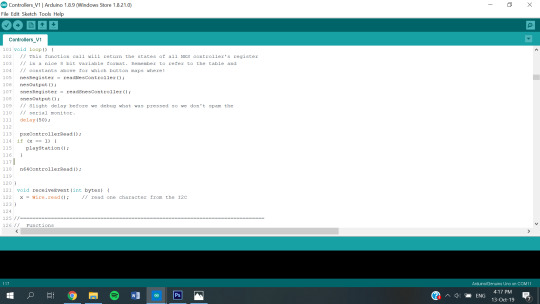
What I came across was ‘12C Communication’.
https://howtomechatronics.com/tutorials/arduino/how-i2c-communication-works-and-how-to-use-it-with-arduino/
First I wrote this code using their example of blinking an LED based off code form the other Arduino, then I re-wrote it to run the Playstation controller and tell the other Arduino when any button had been pressed, in the same way I had done with all of the other controllers.
I was then able to daisy chain two Arduino’s together in a Master/Slave configuration. The Playstation 1 controller was plugged into the ‘master’ arduino, which sent data to the ‘slave’ arduino. The ‘slave’ arduino was my main Arduino which could then use the data from all of the controllers to tell processing what tracks to play as well as run the glitch protocol, which I hadn’t made at this point.

Master Program - Merge NES and SNES Programs: Done
Master Program - Merge PSX with NES and SNES
This merge was relatively easy. However every time I merged a program I began to realise I should have coded more efficiently, but that is something I would have done with more time.

Master Program - Merge Daisychained PS1 with PS2, NES and SNES
This is simple, and now I had the daisy chained controller from earlier working with the other code meaning all I needed to add was the N64 code.

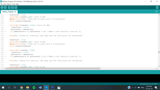
Master Program - Merge N64 with all other controllers
Once Tim and Simon got this working this was a smooth and easy merge. This completed merging the programs for the controllers, and put me closer to being finished than ever before. It’s great that they got this N64 code working as I was quite concerned that it wouldn’t function.
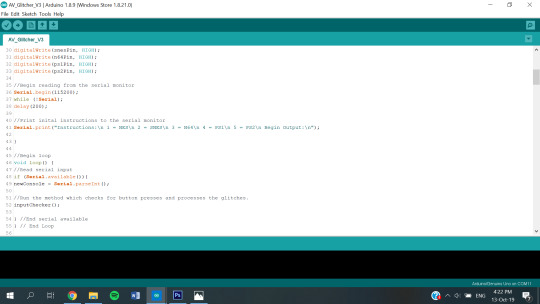
Master Program - Write ‘glitching’ protocol
It took a couple of versions of code to make this operational, but eventually I was able to make the code execute the visual glitching which is the most major visual part of the final outcome. Since processing just reads from the serial monitor, it was easy to add Processing communication at the same time I did this for the later sound output.
https://learn.sparkfun.com/tutorials/connecting-arduino-to-processing/all
Master Program - Add processing communication for music: Done
Master Program - Add AV control to the controllers
This created the ‘finished’ program which was ready to run. I merged my past AV switcher code into this program and I had the five controllers controlling the video outputs. All seemed well, however, there was something I was curious about from the beginning that I couldn’t answer until I was done (which I also didn’t think would be the day of the deadline). This was - will the controllers work in the consoles when they are spliced into the Arduino?
Now that it was all coming together, it was time to put it all together. I plugged all of the controllers, the two Arduino’s and the AV switcher into one curcuit and BOOM! It worked. The AV’s switch and the sound is responsive.
Now I need to do some slight changing on the code because the buttons on the N64 controller press themselves sometimes I want to create a ‘safety net’. However, this is something I can do for open studio and I am confident I now have a completed proof of concept for submission. It’s not completed in the way I had hoped, we didn’t put time into our installation and its a little glitchy - which kind of adds to the experience in its own way.

Master Program - Add 'controller security’
Now cool, its 10pm on Thursday night and its all due in the morning. I’m being kicked out of studio by security as its time to go. The sound works (cheers Tim and Simon), the AV’s glitch and all I have is a little glitch I can fix later. Nice.
Wait? Can I play the games? No!
The NES crashes the console, and somehow the console is powered by the Arduino through the controller port, so for the safety of the console we now can’t play it with the same controller.
The SNES with a little extra code doesn’t mind at all and its smooth sailing as planned.
The N64 plays like a gem with no extra code.
The PS1 and PS2 controllers are completely unresponsive, and due to the structure of the code in the library its no easy fix to figure out how to allow them to be played with the same controllers.
This is a massive blow to the outcome, and one I couldn’t have tested until I finished the code, which is hours before submission. I have spent so many hours on this and I really want it to work. Unfortunately I just don’t know how. I’m sure with more time I could iron out these errors, but until then the visuals and audio are sick and its great to have an outcome.
Another issue is that PAL and NTSC don’t glitch together well and overall PAL glitches better. So since the NES and SNES are NTSC the glitches don’t look as good as they could with some of the consoles.
It definitely took at least four times longer than I thought, and I shouldn’t have taken on so much technical stuff. However, this was a passion project as I really enjoy working with retro tech and especially retro gaming tech. Thanks to Tim and Simon for all your hard work, I couldn’t have done it without you.
Future Directions:
Make the games play
Fix the N64 Glitch
Create a good installation for it.
Source all PAL based consoles
0 notes
Text
Pomodoro timer and alarm clock Experiment 2: LCD Integration
About LCDs and the I2C interface
As per the previous experiment, let’s begin by understanding what an LCD is. According to wikipedia: “ A liquid-crystal display (LCD) is a flat-panel display or other electronically modulated optical device that uses the light-modulating properties of liquid crystals. Liquid crystals do not emit light directly, instead using a backlight or reflector to produce images in color or monochrome. “
So, in order to display data to the user, we use an LCD screen. The one we are using can display 16 characters per line, consisting of a total of 2 lines (16*2), but there are other screens of different sizes (such as 20*4). The LCD screens can communicate with the microcontroller (I/O communication) in different ways. For our experiment, we will be using the I2C interface. The I2C interface links the 16 pins of the classical LCD screen into only 4 pins: GND (for ground), VCC (for powering it up), SDA and SCL (for communication protocols). The I2C interface board also contains a potentiometer (the blue square) that regulates the light intensity of the character boxes. Note that in case your characters are barely visible, you might need to turn the potentiometer to increase the intensity. We can also use the two additional pins located on the left side of the back (which are usually covered) to connect them to a potentiometer.


Connecting the physical parts
Similar to the last experiment, we begin by connecting Male to Female cables to the LCD screen.

Next, we connect the wires linked to VCC and GND onto the breadboard. VCC to any column linked to the Positive Bus and GND to any other column linked to the Negative Bus, just like how we connected the Real-time Clock. Next, we connect the two wires coming from the SDA and SCL pins to the pins 20 (SDA) and 21(SCL) accordingly. Some microcontrollers might have different numbers for those pins, but they would still be labeled properly, so look on your board for those two names.
After that, plug the potentiometer into the breadboard, and connect it to the two wires from the opposite side to any two of the columns where the potentiometer is plugged into.
‘A potentiometer is a three-terminal resistor with a sliding or rotating contact that forms an adjustable voltage divider. If only two terminals are used, one end and the wiper, it acts as a variable resistor or rheostat’ (Wikipedia, 2019). It’s purpose is to regulate the intensity of the voltage that passes through the LCD screen by opposing resistance.
This is the diagram of our circuit:


Note: the diagram is not entirely accurate as there was no LCD screen available for illustration that had the I2C interface. Consider the first pin to be GND, the second VCC, the third SDA, the fourth SCL, and the 5th and the 6th the two isolated pins on the left side of the back of the I2C interface.
Programming the LCD
In order to program the LCD, we need to use an additional library. The LiquidCrystal_I2C library that I used can be found at this link.
This library allows us to construct an object which contains methods that control the LCD. First, we construct the object with the following line:
LiquidCrystal_I2C lcd(0x27,16,2);
The first parameter passed is the address of the screen. I believe that all 16*2 sized LCD screens will have the address 0x27, while 20*4 sized LCD screens have the address 0x3F.
The following sketch (provided by instructables.com) can help you identify the right address of your screen:


Note: the library needed for this particular sketch can be downloaded at this link.
The second and third parameter of the constructor is related to the size of the screen: the number of characters per line, the number of lines.
In the setup() method of the sketch, we call the following lines to initialize the screen:
lcd.init(); lcd.backlight();
In the loop() method, we do the same thing as from the last experiment, but we are now printing on the lcd object instead of the Serial, as well as using the lcd.clear() method to clear previous content and lcd.setCursor() to tell the screen on which line to display the text.
When displaying text on the LCD, always keep in mind that we can have a maximum of 16 characters per line, so adjust it accordingly.
The code of the complete sketch:


After uploading the following code to the microcontroller, this is what you should achieve:

If you want your values to be displayed in a double digit manner (e.g. show 05 instead of 5), add the following line of code for every variable printed:

This video explains the flow of electricity in this circuit.
vimeo
In the next experiment, we will be adding a push-button and a buzzer to our project, have the button turn the display on and off, and the buzzer trigger at certain intervals of time.
The complete code can be found HERE !
The source code can be found HERE!
Technical evaluation
To get the LCD to work was quite troublesome at first. The first LCD screen I bought did not have an I2C interface, and it required soldering, for which I did not have the tools at hand. I had to purchase a second one, but that was still not as easy as I hoped. There are a lot of libraries for LCD screens, and it took about four tries until I have found one compatible with my screen. Once I managed to get the circuit going, I encountered another issue. The characters on the screen were very faded. After inspecting the I2C interface, I noticed that there is an additional potentiometer which had to be spinned a little to increase the intensity of the light. That solved my issue. After that, printing characters to it was very simple and also fun. Apart from those issues, everything went quite smoothly. I consider this to be one of my greatest achievements in using physical components, as I always thought LCD screens were quite a complicated tool, and this made me more confident that I could use more advanced parts in the future.
References
https://www.instructables.com/id/How-to-use-an-LCD-displays-Arduino-Tutorial/
https://en.wikipedia.org/wiki/Potentiometer
0 notes
Text
How I2C Communication Works and How To Use It with Arduino
http://howtomechatronics.com/tutorial...► Find more details, circuit schematics and source codes here.In this tutorial we will learn how the I2C communication protocol works and also we will make a practical example of it with the Arduino Board and a sensor which uses this protocol. You can watch https://www.youtube.com/watch?v=6IAkYpmA1DQ&feature=share http://img.youtube.com/vi/6IAkYpmA1DQ/0.jpg March 18, 2019 at 03:48PM
0 notes
Text
Project Overview
This NodeMCU IoT project is a simple demonstration on how to send sensor data to the Internet. Powered by a NodeMCU ESP8266 microcontroller, this project is able to show temperature, humidity and atmospheric pressure to any MQTT subscriber.
Introduction
Using MQTT is much faster than using HTTP because of reduced overhead. In fact, MQTT is one of the preferred protocols for Internet of Things. To use MQTT, we need a broker and there are lots of them! For this project, I used Shiftr.IO. I already detailed how to use the MQTT protocol with the NodeMCU so kindly check that out first.
Materials
For temperature and humidity, I used SHT1x from DFRobot. For the atmospheric sensor, I used the old reliable BMP085. My Arduino BMP085 tutorial covers how to use this sensor with the Arduino. Since the NodeMCU uses the same Arduino IDE and as long as the special core is installed, a similar sketch from that tutorial will be used here.
[tie_list type=”checklist”]
NodeMCU
SHT1X Temperature and Humidity Sensor
BMP085 Atmospheric Pressure Sensor
[/tie_list]
Another requirement for this project is an account in Shiftr.IO which is totally free. I’ve created an “environment-monitor” channel in Shiftr and was promptly given username and passwords.
The MQTT library is required and is downloadable here. Also, you’ll be needing the SHT1X library and the BMP085 library, both thankfully are NodeMCU-compatible.
Wiring Diagram
The SHT1X library uses software SPI while the BMP085 uses I2C. The default I2C pins of the NodeMCU is at D1 (SCL) and D2 (SDA) or GPIO5 and GPIO4. Naturally, the BMP085’s SDA and SCL pins should be connected to those pins. As for the the SHT1X, I decided to use the D3 and D4 pins for clock and data respectively. Here is the Fritzing diagram:
Arduino Sketch
The sketch is similar to that in my MQTT tutorial [https://www.teachmemicro.com/nodemcu-mqtt-tutorial/]. First, connect to the MQTT broker through
client.begin("broker.shiftr.io", WiFiclient);
Then I connected to the MQTT channel using
client.connect("environment-monitor", "<username>", "<password>")
The username and password is found on the URL of the MQTT channel. For example, if this is your URL: mqtt://7fb2fd2f:[email protected] ( found in namespace settings). Your username is 7fb2fd2f and the password is b9f1e26ae8d3dac8.
To publish data, I used
client.publish("environment-monitor/temperature", (String)temp_c);
There is no need to create the /temperature topic as it’s automatically created once you call the function above. Of course, you can publish multiple topics:
client.publish("environment-monitor/temperature", (String)temp_c); client.publish("environment-monitor/humidity", (String)humidity); client.publish("environment-monitor/pressure", (String)pressure);
Anyway, here’s the full sketch:
/*NodeMCU IoT Environment Monitor * * By Roland * * From https://www.teachmemicro.com/nodemcu-iot-environment-monitor */ #include <SHT1x.h> #include <Wire.h> #include <Adafruit_BMP085.h> #include <ESP8266WiFi.h> #include <MQTTClient.h> // Replace with your network credentials const char* ssid = "Les Boise Engr. Innovations"; const char* password = "tingkarol"; WiFiClient WiFiclient; MQTTClient client; unsigned long lastMillis = 0; String page = ""; String text = ""; String data; // Specify data and clock connections and instantiate SHT1x object #define dataPin 2 //D4 #define clockPin 0 //D3 SHT1x sht1x(dataPin, clockPin); Adafruit_BMP085 bmp; float temp_c; float temp_f; float humidity; float pressure; void setup() { Serial.begin(115200); // Open serial connection to report values to host Serial.println("Starting up"); if (!bmp.begin()) { Serial.println("Could not find a valid BMP085 sensor, check wiring!"); while (1) {} } WiFi.begin(ssid, password); //begin WiFi connection // Wait for connection while (WiFi.status() != WL_CONNECTED) { delay(500); Serial.print("."); } Serial.println(""); Serial.print("Connected to "); Serial.println(ssid); Serial.print("IP address: "); Serial.println(WiFi.localIP()); Serial.print("connecting to MQTT broker..."); client.begin("broker.shiftr.io", WiFiclient); connect(); } void connect() { while (!client.connect("environment-monitor", "7fb2fd2f", "b9f1e26ae8d3dac8")) { Serial.print("."); } Serial.println("\nconnected!"); client.subscribe("environment-data"); } void loop() { // Read values from the sensor temp_c = sht1x.readTemperatureC(); humidity = sht1x.readHumidity(); pressure = bmp.readPressure(); client.loop(); if(!client.connected()) { connect(); } if(millis() - lastMillis > 1000) { lastMillis = millis(); client.publish("environment-monitor/temperature", (String)temp_c); client.publish("environment-monitor/humidity", (String)humidity); client.publish("environment-monitor/pressure", (String)pressure); } }
Images
Here’s some pictures of my actual setup:
Video
Project Files
I provided the project files for anyone who want to replicate this project:
[wpdm_package id=’2288′]
Good luck!
NodeMCU IoT Environment Monitor Project Overview This NodeMCU IoT project is a simple demonstration on how to send sensor data to the Internet.
0 notes
Text
Erlang user conference notes, translated.
Jonas Boner, author of Akka ---------------------------- Talks a lot about reliability, resiliency but doesn't say how, instead of it shows nice pictures with meercats, Conway's game of life and so on. Let us split the system to number of interacting agents, and let them interact. All states should be known, unknown states should not exist (hard to argue). How to know all states is unknown though. Converging promises and diverging commands. Kenneth Lundin, OTP 20 highlights --------------------------------- A lot of improvements: garbage collector, binary parts, unicode aroms, better maps, ets, and so on. Failed to split OTP as planned, however work is going on. See the changelog, release is planned at 21 of June. Jesper L. Andersen, GraphQL in Erlang ------------------------------------- http://ift.tt/2qdi8rk GraphQL allows a client to declare what it wants from sever. What is possible is described by schema, schema is compiiled and checked server-side. Query interpretation takes microseconds, most of load is to fetch data from storages. Each schema type is represented by Eralng module with known API. Types in GraphQL and types theory relation (positive/negative types), this is not emphasized in GraphQL docs. Author wrote a lenghtly tutorial. Paweł Antemijczuk и Maarten Faddegon, Anti-Patterns in the Wild --------------------------------------------------------------- How write a bad code in Erlang. Same old story: don't write huge functions, don't use huge state, don't nest case clauses. They fear to use Erlando in production due to maintenance concerns, they tried and failed Wrangler (steep learning curve, unclear results, don't like Emacs). To sum up: it is impossible to refactor Erlang code automatically and semi-automaticcally at the moment and nearest future. Write tests instead. Mark Allen, Sagas in Erlang: Distributed Transactions Without Locks ------------------------------------------------------------------- For the reason unknown declared a left fold operation a transaction (it is not), distributed in fact not so distributed, and so on. Why to talk about this is unclear. Peer Stritzinger, Fixing Erlang’s Distribution Protocol ------------------------------------------------------- They tried to use Erlang on microcomputers for industrial automation and then discovered that Erlang distribution protocol is broken by design: 1. full-mesh networking model 2. messages are processed sequentally, and one huge can block whole queue 3. primitive security model Because of that they want to fix the protocol, however how he described the fix looks more or less like TCP/IP stack itself but over the node links (which are TCP already). Weird. Peter Van Roy, Ditching the Data Center: How to Stop Worrying and Love the Edge ------------------------------------------------------------------------------- This time truly distributed computations over unreliable network. Nodes know about each other with Gossip family of protocols, all calculations should be with CRDT. At the moment CRDT have limited use, but where they could be used then use cases are good. They are doing research, have funding till 2020, and plans till 2050. Impressive. The idea is to write programs as expressions over CRDT, sort of map: A -> B, and there is a special language lasp. Kostis Sagonas, Adventures in Corfu: Testing and Verifying Chain Repair Protocols using Concuerror -------------------------------------------------------------------------------------------------- Started with some Greece advertisement, however continued: they have a tool to test concurrency in Erlang by building all possible message sequence combinations, and trying all of them. If a program fails under this test then there is certainly a bug, and if program doesn't fail, then there are no bugs (with high probability). All possible cases could be tried, but it takes time. There are some ways to speed up process, and plans how to make it parallel. One unexpected use case: Scott Lystig Fritchie who works on CorfuDB discovered a bug in distribution protocol, but concuerror discovered a bug in suggested fix to previous bug. This was achieved by modelling protocol with Erlang entities (processes, messages). Very interesting. Justin Schneck, Keynote: The Demarcation of the Edge of Innovation ------------------------------------------------------------------ Talks about dependencies, food recepies, all are doing something, everything depends on everything, and so on. They took Linux kernel, and Erlang, and made it run on Raspberri Pi, and then called it a platform. Was unable to stand this marketing bullshit and left. Andrea Leopardi, Update from the Elixir Core Team ------------------------------------------------- Elixir is stable and evolving, planned release is 1.5, good interaction with OTP team, built-in property tester, and so on. Clara Benac Earle, Building Distributed and Robust Multi-Agent Systems (MAS) ---------------------------------------------------------------------------- Talks about agents with beliefs, goals and logic. Some people describe those agents using special language Jason, JVM targeted. Speakers were able to translate this language to BEAM and are very happy. Robustness and distribution are inherited from BEAM, sort of. Loïc Hoguin, A Tale of 2.0 Cowboys ----------------------------------- Soon Cowboy 2.0 will be released with HTTP/2 support and better architecture. Used maps everywhere, better process management, gen_statem. Handlers could return list of commands. Rewrote whole documentation in php-style (one function per page), wrote a lot of tests for specs, a lot of work. Cowboy 1.x is a part of RabbitMQ, and other his projects. Has plans to write REST framework, nobody are doing REST correctly. Much sponsors left past two years, has no money because of that. Claudia Doppioslash, Building Single Page Web Applications with Purescript and Erlang ------------------------------------------------------------------------------------- Rewrote the app from Elm to Purescript (last year talk was about Elm). Elm is not good enough (simple types, one true architecture). Purescript has rich type system, and could be compiled to Erlang. They are using BERT between client and server due to encoding/decoding server-side is much quickier than JSON. How Erlang is related to this project is completely unclear. Adam Lindberg, Robotics and Sensors Using Erlang on Embedded Systems with GRiSP ------------------------------------------------------------------------------- Developed a custom atmel-based board with rich periphery (wifi, usb, gpio, i2c, spi, uart, 1-wire), and managed to run RTEMS with BEAM on it. This allows to use Erlang to manage and program the device. Erlang used is outdated (16.x), they have plans to update it alongside with build process. Selling price is 180 euro, intended use case is industrial automation. Unclear though why is this better than Orange Pi ($10 with delivery) with Armbian and Erlang. Joe Armstrong и Sam Aaron, Distributed Jamming and Composition with Sonic Pi and Erlang --------------------------------------------------------------------------------------- A stand-up comedy show. Joe Armstrong discovered MIDI, and is eager to share this knowledge with broad audience. Suddenly MIDI has messages, and you can exchange them over network. Sam Aaron demonstrated how his Sonic Pi works. Here we have a program to generate sounds, how cool it is. Also you can have effects. Logic Pro is written by idiots. How Erlang is related, again? comments via jamhed http://ift.tt/2srOSCR
0 notes
Text
ESP32 Based Web Server for Temperature and Humidity Monitor using DHT11 Sensor
youtube
ESP32 Based Webserver for Temperature and Humidity Monitor using DHT11 Sensor. ****************************************************************** If You Want To Purchase the Full Project or Software Code Mail Us: [email protected] Title Name Along With You-Tube Video Link Project Changes also Made according to Student Requirements http://svsembedded.com/ è https://www.svskits.in/ M1: +91 9491535690 è M2: +91 7842358459 ****************************************************************** 1. ESP32 DHT11 Temperature & Humidity Monitor on Web Server, 2. Interface DHT11 DHT22 with ESP32 & Display Values Using Web Server, 3. IoT Temperature and humidity , 4. ESP32 Temperature and Humidity Monitor using Arduino IDE, 5. DHT11/DHT22 Web Server – Temperature and humidity, 6. ESP32 DHT11 Temperature & Humidity Monitor on Web Server, 7. Monitoring temperature and humidity with ESP32, 8. ESP32 DHT11/DHT22 Web Server using Arduino IDE – Pinterest, 9. Interfacing DHT11 Temperature and Humidity Sensor with Web Server, 10. interface dht11 dht22 with esp32 and display values on web server, 11. ESP32 Based Webserver for Temperature and Humidity, 12. ESP32 DHT11/DHT22 Web Server using Arduino IDE | Iot, 13. ESP32 web server with the DHT11 or DHT22 that displays temperature and humidity, 14. ESP32 with DHT11 Temperature Humidity Web Server, 15. Interface Embedded Protocol Embedded Sensor ESP32 ESP32 Arduino Core ESP32 Interface ESP32, 16. IoT Based Patient Health Monitoring on ESP32 Web Server, 17. esp32 dht11 mqtt - esp32 dht11 blynk, 18. esp32 web server - esp32 dht11 thingspeak, 19. esp32 async web server - dht11 esp32 library, 20. esp32 dht22 - esp32 temperature sensor, 21. AWS IOT with Arduino ESP32 - Tutorials - Explore Embedded, 22. Temperature and humidity reading by ESP32 – OpenLabPro, 23. ESP32 and SHT21 humidity and temperature sensor example | ESP32, 24. Tracking down the Vehicle Collision Detection and Messaging System using GPS and GSM 25. Sensor Data Monitoring Over CAN BUS Using Arduino | Interfacing MCP2515 CAN BUS Module with Arduino 26. How to Make A Simple WiFi Controlled Robot Car (NodeMCU) | Wifi RC Car ESP8266 App - NodeMCU (ESP12E) 27. Weather Station: DHT11 Temperature and Humidity Sensor Arduino 2.4″ TFT LCD Touch Shield - SPFD5408 28. Control FAN Speed and LIGHT using TV Remote 29. Smart Crop Protection From Wild Animals With Alert Using Arduino | Field Sensor Monitoring with WiFi 30. How to Transfer Data From One USB Hard Drive to Another USB 31. IoT based Precision Agriculture 32. IOT BASED SMART BLOOD BANK SYSTEM 33. Blood Bags Weight Monitoring Using 2 load cells 34. GSM Motor Pump controller (Mobile Motor Starter) | Automatic Mobile Starter | Mobile pump starter 35. Bus Boarding System for Visually Impaired Passengers 36. Design and Implementation of RFID-based Fuel Dispensing System 37. Cable Fault Detection System with SMS Notification using Arduino, GSM and GPS 38. 2.4'' TFT Touch Screen Restaurant Menu Ordering System Using Arduino 39. IoT Based Air, Water, Noise, Dust, Humidity, Gas, CO and Temperature Monitoring System using Arduino 40. IOT BASED SMART GARBAGE MONITORING SYSTEM USING NODEMCU + GSM + GPS + ULTRASONIC 41. i2c lcd with nodemcu | Interface I2C LCD Using ESP8266 NodeMCU | I2C LCD on NodeMCU With Arduino IDE 42. GPS + GSM Based Underground Cable Fault Detection with Arduino 43. Electric Shock + GPS Hand Glove Developed to help Women's Safety & Self Defense 44. GSM Based Motor Controller in Irrigation by Using Sensor's [ Soil Moisture + Tank Water Level ] 45. Petrol Bunk Automation with Prepaid Card using GSM Identification 46. IoT Based Water Level Monitoring System 47. Smart Garbage Monitoring System Using Internet of Things (IOT) 48. Automated Smart Trolley with Smart Billing Using Arduino | RFID Based Smart Shopping Cart 49. Traffic Signal Management and Control System using Arduino with 4 servo motors 50. Hand Gesture Controlled Robot using Arduino | How to Make a Gesture Control Robot 51. Arduino Based Vehicle Accident Alert System Using GSM, GPS, MEMS, VIBRATION and SOS 52. How to Make VOICE CONTROLLED Car by using ARDUINO 53. Women Safety Device With GPS Tracking & Alerts 54. GPS + GSM Based Smart Blind Stick Tracking System Project 55. Auto Metro Train to Shuttle Between Stations 56. IOT Underground Cable Fault Detector Project 57. Reading GPS Data With a Raspberry Pi | GPS on Raspberry Pi | Raspberry Pi GPS reading 58. Smart Glove For Deaf and Dumb using Arduino Controls Remote Devices 59. voice based notice board using android and arduino
0 notes