#what is i2c protocol
Explore tagged Tumblr posts
Visit Tumblr Blog
Explore Tumblr blogs with no restrictions, modern design and the best experience.
Last Seen Tumblr Blogs


Fun Fact
In 2020, 44% of users from Denmark used Tumblr daily.
Text
How i2C protocol works....
#mobicationhub #mobicationhub9509959090 #Protocol #reelsfypシ #i2c #institute #phonerepair #mobilerepaircoursejaipur #mobilerepairing #working #1monthcours #laptop
#i2c protocol#i2c protocol tutorial#protocol#spi protocol#communication protocols#i2c protocol vs spi protocol#communication protocol#how i2c protocol works#i2c protocol - inter integrated circuit protocol#i2c communication protocol#i2c protocol working#serial communication protocol#inter integrated circuit protocol#inter-integrated circuit protocol#i2c bus protocol#i3c protocol#what is i2c protocol#basics of i2c protocol#spi protocol tutorial
0 notes
Text
https://www.futureelectronics.com/p/semiconductors--comm-products--i2c/pca9515adp-118-nxp-7183946
What is I2C communication, serial communication bus, I2C logic
PCA9515A Series 3.6 V 5 mA 400 kHz 6 pF I2C-bus Repeater - SOIC-8
#NXP#PCA9515ADP#118#Comm Products#I2C#What is I2C communication#serial communication bus#I2C logic#Surface Mount I2C bus repeaters#Wire Interface Bus#USB to I2C converter#Encoder motor driver#i2c communication protocol#I2C bus switches
1 note
·
View note
Text
https://www.futureelectronics.com/p/semiconductors--comm-products--i2c/pca9515adp-118-nxp-5973557
I2c bus, I2c communication protocol, Inter-Integrated Circuit, spi interface
PCA9515A Series 3.6 V 5 mA 400 kHz 6 pF Surface Mount I2C-bus Repeater - SOIC-8
#Comm Products#I2C#PCA9515ADP#118#NXP#What is I2C communication#High Speed CAN#i2c pins#digital integrated circuits#I2c bus#I2c communication protocol#Inter-Integrated Circuit#spi interface#expanders#I2C bus repeaters
1 note
·
View note
Text
We're vibin' with Claude 3.7 and writing uBlox drivers 😎🤖🛰️
Heeeey, we're just having a super chill vibe here at the desk of Ladyada—writing a driver for the uBlox M8Q
https://blog.adafruit.com/2024/09/10/a-mini-gps-from-ublox-with-i2c-and-uart
, which has both I2C and UART interfaces. As expected, it can do everyday NMEA output, but it can also do UBX, a "compressed" protocol for advanced data reads and writes over I2C/UART—or even SPI on some other chips.
However, the UBX protocol is a hugely complex driver to implement, with dozens of commands and hundreds of flags. But why stress when you can viiiibe? We're using this beast of a spec as an excuse to try out the new Claude 3.7, which is doing great at chomping through the UBX documentation roughage and giving us some nice code on the other side. Within an hour, we're able to connect and switch to UBX mode by sending a well-formed message and receiving an ACK.
What we like about coding with a good LLM is that it does the work we sometimes get lazy over, like handling various error conditions, timeouts, and verbose error messages.
13 notes
·
View notes
Note
WARNING: LONG ASK INCOMING
For hobby electronics there’s two major kinds of processors: Microcomputers and Microcontrollers. Microcomputers are small full computer systems like the Raspberry Pi, they typically run a general-purpose OS (typically some flavor of Linux) and are useful for the kinds of projects that require basically a full computer to function, but not necessarily individual sensors. They’re a great place to start for people who don’t know a whole ton about programming or working with individual components because they typically can output a true GUI to a screen and have the capabilities of a regular desktop computer. They have a main processor, true RAM, and either large on-board storage space or a way to read a storage device, like an SD card.
Microcontrollers are less complicated (component wise) than microcomputers, but as a result are more difficult for total beginners to begin working with. They’re typically primarily a SoC (System on a Chip) processor without discrete RAM modules and a very small EEPROM (on-ship storage space) and need to have components wired and configured to them to be able to do much more than being a fancy calculator. They’re used for when you need something to carry out electronic functions or get sensor readings, but not necessarily a full operating system, so they’re best suited for small/integrated applications. Your helmet uses a microcontroller to control the LEDs you used in the Cunt Machine post.
I build high-power model rockets as a hobby and with my university team, so I work with both kinds of processor as part of designing payload systems. I typically prefer microcontrollers in these as most of what we do doesn’t need an actual OS to run, and they’re smaller/lighter than microcomputers. One of the advantages of a microcontroller is that it runs a Real-Time OS (RTOS) which forgoes all the user-friendliness of things like windows and linux to instead be the bare minimum backend necessary to run code uploaded into the processor.
The main advantage of using a microcontroller is really that they’re typically a lot cheaper than microcomputers are and are plenty powerful for really embedded applications. They also make other parts of whatever system is being built cheaper/easier to integrate because they require less overhead to function - the raspberry pi needs a minimum of 5 volts of power to work, while a chip like an ESP32-PICO can run at 1.8V.
The main way you make sensors/buttons/peripherals work with a microcontroller is via digital communication busses. There’s a few protocols, the most common being I2C, SPI, and UART. I’ll talk about I2C since that’s generally the most common. With I2C each component is assigned a 2-byte “address” that they’re identified by. When the controller sends a request signal on the I2C data bus, every sensor along the line will return their own signal, marked with their address so that they can be identified. It allows for a large number of devices to be put on the same lines and you can daisy-chain them through each other to the microcontroller.
I’ll be honest I really can’t think of a good way to say much more on the subject as like a starting message because I’ve been working with computers so long all the tech stuff for me is second nature, but if you have any questions ask away I can probably answer them or google them.
.
#AAAAAAAAAAAAAAAAAAAA TY INFORMATION#no yeah this is either really beginner friendly or. friendly to how much i have learned so far#tysm!!!! your insight is consistently so helpful <3#ask#lobsterbitches
27 notes
·
View notes
Text
What are interrupts used for mainly?
In embedded systems, interrupts are a crucial mechanism that allows a processor to respond immediately to important events, even while executing other tasks. Instead of continuously checking (or polling) for events like button presses, sensor data, or communication input, an interrupt automatically notifies the processor when an event occurs, allowing for faster and more efficient operation.
Interrupts essentially "interrupt" the normal execution flow of a program to handle urgent tasks. This is done using an Interrupt Service Routine (ISR) — a special function that is executed in response to the interrupt. Once the ISR finishes, the processor resumes its previous task. This ability to react instantly is vital in real-time applications, such as reading data from sensors, responding to user input, or handling communication protocols like UART, SPI, or I2C.
There are two main types of interrupts: hardware and software. Hardware interrupts are triggered by peripherals or external devices (like a temperature sensor), while software interrupts are triggered by programs to signal specific events internally.
Using interrupts helps optimize CPU usage, reduce power consumption (as the CPU can sleep until interrupted), and ensure timely responses to critical events. However, poor interrupt handling can lead to issues like missed events or system crashes, so proper design and prioritization of interrupts are essential.
Overall, interrupts form the backbone of responsiveness in modern embedded systems and are indispensable for designing efficient, real-time applications. For those aspiring to build a career in this domain, mastering interrupt-driven programming is a key skill. A structured embedded systems course with placement can provide hands-on experience and career opportunities in this high-demand field.
0 notes
Text
Embedded Controls Development: From Design to Deployment

Embedded controls development is a critical area in embedded systems engineering, involving the design, programming, and integration of control systems into hardware platforms. These systems are typically found in devices that perform dedicated functions, ranging from consumer electronics to industrial automation and automotive applications. The development process requires a combination of hardware knowledge, software engineering, and systems integration skills.
What Are Embedded Controls?
Embedded controls are computer-based systems that control specific functions within a larger mechanical or electrical system. They use microcontrollers, digital signal processors (DSPs), or microprocessors to monitor inputs from sensors, process data according to a control algorithm, and output control signals to actuators or other system components. These control loops can be simple (like turning on a fan when a sensor detects high temperature) or complex (like managing engine timing and fuel injection in modern vehicles).
Development Lifecycle
The development lifecycle for embedded controls typically follows several key stages:
Requirements Definition: Understanding what the control system needs to do. This includes identifying input/output interfaces, environmental constraints, performance requirements, and safety or compliance standards.
System Design: Creating a high-level architecture that defines how software and hardware will interact. This stage also involves choosing the right microcontroller or processor, selecting sensors and actuators, and outlining communication protocols.
Software Development: Writing code for the embedded control system, often in C or C++. Developers must consider memory limitations, real-time constraints, and hardware-specific details. This stage includes implementing control algorithms, handling interrupts, and developing communication interfaces such as I2C, SPI, UART, or CAN.
Hardware Integration: Integrating the embedded software with physical components. This includes setting up the development board, connecting sensors and actuators, and testing signal integrity and power consumption.
Testing and Validation: Rigorously testing the control system to ensure it functions as expected under various conditions. Unit testing, integration testing, and hardware-in-the-loop (HIL) simulations are commonly used to verify performance and reliability.
Deployment and Maintenance: After development and testing, the system is deployed into the final product. Ongoing maintenance may involve firmware updates, bug fixes, or performance improvements.
Tools and Platforms
A wide range of tools are used in embedded controls development, including:
Integrated Development Environments (IDEs): Tools like Keil µVision, MPLAB X, STM32CubeIDE, and Arduino IDE are popular for writing and debugging code.
Real-Time Operating Systems (RTOS): Systems such as FreeRTOS or VxWorks provide scheduling, task management, and synchronization capabilities for time-sensitive applications.
Version Control Systems: Git is widely used to manage code versions and support collaborative development.
Simulation and Modeling Tools: MATLAB/Simulink is frequently used in control systems design for simulation and code generation.
In-Circuit Debuggers/Programmers: Tools like JTAG or SWD interfaces allow developers to program and debug the target microcontroller directly.
Challenges in Embedded Controls Development
Developing embedded control systems presents several challenges:
Resource Constraints: Embedded systems often have limited CPU power, memory, and energy availability. Efficient coding and hardware optimization are essential.
Real-Time Requirements: Many control systems must respond within strict timing constraints. Missed deadlines can result in system failure or unsafe behavior.
Hardware Dependence: Embedded software is closely tied to specific hardware, requiring deep knowledge of the processor, peripherals, and electrical characteristics.
Debugging Complexity: Diagnosing problems in embedded systems can be difficult due to limited visibility into internal states and limited logging capabilities.
Safety and Reliability: In industries like automotive or medical devices, the control systems must meet rigorous safety standards such as ISO 26262 or IEC 62304.
Applications
Embedded controls are used in countless applications:
Automotive Systems: Engine control units (ECUs), anti-lock braking systems (ABS), adaptive cruise control, and infotainment systems.
Consumer Electronics: Smart thermostats, washing machines, and robotic vacuum cleaners all rely on embedded control systems.
Industrial Automation: PLCs and industrial controllers manage processes on factory floors, often integrating with SCADA systems.
Aerospace and Defense: Flight control systems, unmanned aerial vehicles (UAVs), and radar systems.
Medical Devices: Infusion pumps, pacemakers, and diagnostic equipment all include embedded control systems to ensure safe and accurate operation.
Trends and Future Directions
The field of embedded controls is rapidly evolving. Several key trends are shaping the future:
IoT Integration: Many embedded systems are now connected to the internet, allowing for remote monitoring, control, and firmware updates.
Edge Computing: More processing is being done on the device itself, reducing the need to send data to the cloud and improving response times.
AI and Machine Learning: Embedded systems are beginning to incorporate ML algorithms for pattern recognition, predictive maintenance, and adaptive control.
Model-Based Design: Tools like Simulink allow engineers to design control systems graphically and automatically generate embedded code.
Cybersecurity: As systems become more connected, securing embedded control systems against hacking and data breaches is becoming essential.
Conclusion
Embedded controls development by Servotechinc is a complex but vital discipline that sits at the heart of modern technology. From managing vehicle dynamics to enabling smart home features, embedded control systems play a crucial role in ensuring that machines operate efficiently, safely, and intelligently. As technology advances, the demand for skilled engineers in this domain will only continue to grow.
0 notes
Text
A Comprehensive Guide to Firmware Development

In the world of embedded systems and smart devices, firmware plays a critical role in enabling hardware to function effectively. Whether you're developing IoT devices, automotive systems, or industrial machinery, firmware development is the backbone that bridges hardware and software.
In this blog post, we’ll explore what firmware is, its importance, the development process, tools used, and best practices to ensure efficient and secure firmware solutions.
What is Firmware?
Firmware is a specialized type of software that provides low-level control for a device's specific hardware. Unlike regular software applications, firmware is tightly coupled with the hardware and is often stored in non-volatile memory such as ROM, EEPROM, or flash memory.
Examples of devices with firmware include:
Smartphones
Routers
Smart TVs
Medical devices
Automotive control units (ECUs)
Why is Firmware Important?
Firmware is essential because it:
Controls hardware operations: Without firmware, the hardware components of a device would be non-functional.
Ensures device functionality: It manages startup routines, I/O operations, sensor integration, and communication protocols.
Supports software-hardware integration: Firmware acts as a middle layer, allowing high-level software applications to interact with low-level hardware components.
Enables updates: Firmware can often be updated to fix bugs, enhance performance, or add features.
The Firmware Development Process
1. Requirements Gathering
Understanding the hardware specifications and the device’s purpose is crucial. Developers need to gather requirements from both hardware engineers and end users.
2. Architecture Design
This involves deciding on the architecture and communication protocols (e.g., I2C, SPI, UART), memory usage, and timing constraints.
3. Choosing a Development Platform
Most firmware is written in C or C++ due to their efficiency and hardware-level access. You’ll also need:
Microcontroller/microprocessor datasheets
Board Support Packages (BSPs)
RTOS (Real-Time Operating System), if required
4. Coding and Integration
Firmware code is written to interface directly with hardware. This includes writing drivers for peripherals (LEDs, sensors, motors) and managing power consumption, timing, and interrupts.
5. Testing and Debugging
Testing includes:
Unit testing
Hardware-in-the-loop (HIL) testing
Simulation and emulation tools
Debugging tools such as JTAG and SWD are used to step through code and analyze performance.
6. Deployment
Once tested, firmware is compiled and flashed onto the device using programmers or over-the-air (OTA) update mechanisms.
Tools Used in Firmware Development
Integrated Development Environments (IDEs): Keil µVision, MPLAB X, STM32CubeIDE
Compilers and Toolchains: GCC, IAR Embedded Workbench
Debuggers/Programmers: JTAG, ST-LINK, AVR ISP
Version Control Systems: Git
Simulators/Emulators: QEMU, Proteus
Best Practices for Firmware Development
Write modular and reusable code
Follow coding standards (e.g., MISRA C for safety-critical systems)
Optimize for memory and power consumption
Document thoroughly for maintainability
Implement fail-safes and watchdog timers
Secure your firmware (e.g., with encryption and secure boot loaders)
Plan for firmware updates with mechanisms like OTA updates
0 notes
Text
Understanding the Role of a Pressure Transducer in Modern Industries
Introduction
A pressure transducer is a critical device used across various industries to measure and convert pressure into an electrical signal. These instruments play a vital role in ensuring system efficiency, safety, and accuracy in applications ranging from automotive to aerospace. This article explores the working principle, types, applications, and advantages of pressure transducers, providing a comprehensive understanding of their significance.
What Is a Pressure Transducer?
A pressure transducer, also known as a pressure sensor, is a device that detects pressure and converts it into an analog or digital electrical signal. The output signal can be used for monitoring, control, or data recording purposes. These devices are essential in environments where precise pressure measurement is crucial for operational success.
How Does a Pressure Transducer Work?
The working principle of a pressure transducer involves several key components:
Sensing Element: Detects the applied pressure (e.g., diaphragm, piezoelectric crystal).
Transduction Mechanism: Converts the mechanical pressure into an electrical signal (e.g., strain gauge, capacitive element).
Signal Conditioning Circuitry: Amplifies and processes the signal for accurate output.
Output Interface: Delivers the signal in a usable format (e.g., 4-20mA, 0-10V, digital protocols like I2C or SPI).
When pressure is applied, the sensing element deforms, causing a change in resistance, capacitance, or voltage, which is then converted into a measurable signal.
Types of Pressure Transducers
Different applications require specific types of pressure transducers, each designed for unique operational conditions.
1. Strain Gauge Pressure Transducers
Uses a strain-sensitive element bonded to a diaphragm.
Pressure causes deformation, altering electrical resistance.
Common in industrial and automotive applications.
2. Capacitive Pressure Transducers
Measures changes in capacitance due to diaphragm movement.
Highly accurate and suitable for low-pressure applications.
3. Piezoelectric Pressure Transducers
Utilizes piezoelectric materials that generate voltage under pressure.
Ideal for dynamic pressure measurements in aerospace and defense.
4. Optical Pressure Transducers
Uses fiber-optic technology to detect pressure-induced changes in light properties.
Immune to electromagnetic interference, making them useful in harsh environments.
Key Applications of Pressure Transducers
Pressure transducers are widely used across multiple industries due to their versatility and reliability.
1. Industrial Automation
Monitors hydraulic and pneumatic systems.
Ensures safe operation of machinery by detecting pressure anomalies.
2. Automotive Industry
Measures fuel, oil, and tire pressure for optimal vehicle performance.
Used in engine management and braking systems.
3. Medical Equipment
Critical in ventilators, blood pressure monitors, and dialysis machines.
Ensures patient safety by providing accurate pressure readings.
4. Aerospace & Defense
Monitors cabin pressure, fuel systems, and hydraulic actuators.
Essential for flight safety and performance optimization.
5. Oil & Gas Industry
Used in drilling, pipeline monitoring, and refinery processes.
Detects pressure changes to prevent leaks and equipment failure.
Advantages of Using Pressure Transducers
The adoption of pressure transducers offers numerous benefits, including:
High Accuracy: Provides precise measurements for critical applications.
Durability: Designed to withstand harsh environments (e.g., extreme temperatures, corrosive media).
Versatility: Available in various types to suit different industrial needs.
Real-Time Monitoring: Enables immediate detection of pressure fluctuations.
Compact Design: Fits into tight spaces without compromising performance.
Choosing the Right Pressure Transducer
Selecting the appropriate pressure transducer depends on several factors:
Pressure Range: Ensure the device covers the required measurement range.
Output Signal: Match the output (analog, digital) with the system requirements.
Environmental Conditions: Consider temperature, humidity, and exposure to chemicals.
Accuracy & Resolution: Higher precision is needed for critical applications.
Installation Requirements: Check compatibility with mounting and connection setups.
Maintenance and Calibration
To ensure long-term reliability, pressure transducers require regular maintenance:
Periodic Calibration: Ensures measurement accuracy over time.
Cleaning & Inspection: Prevents contamination and mechanical wear.
Signal Verification: Confirms the output remains consistent with expected values.
Future Trends in Pressure Transducer Technology
Advancements in sensor technology continue to enhance pressure transducer capabilities:
Miniaturization: Smaller, more efficient designs for portable and IoT applications.
Wireless Connectivity: Enables remote monitoring and data logging.
Smart Sensors: Integration with AI for predictive maintenance and diagnostics.
Improved Materials: Enhanced durability for extreme environments.
Conclusion
The pressure transducer is an indispensable tool in modern industries, providing accurate and reliable pressure measurements for diverse applications. Understanding its working principles, types, and selection criteria ensures optimal performance in any operational environment. As technology evolves, these devices will continue to play a pivotal role in automation, safety, and efficiency across multiple sectors.
By leveraging the right pressure transducer, industries can achieve greater precision, reduce downtime, and enhance overall system performance. Whether in manufacturing, healthcare, or aerospace, these sensors remain a cornerstone of pressure measurement technology.

1 note
·
View note
Text
What are the main communication protocols in embedded systems?
Embedded systems rely on various communication protocols to enable efficient data transfer between components, microcontrollers, sensors, and external devices. These protocols can be broadly categorized into serial, parallel, wired, and wireless communication protocols.
UART (Universal Asynchronous Receiver-Transmitter) – A widely used serial communication protocol that facilitates full-duplex data exchange between embedded devices. It requires minimal hardware and is commonly used in debugging and low-speed data transfer applications.
SPI (Serial Peripheral Interface) – A high-speed, full-duplex protocol used for short-distance communication between a microcontroller and peripherals such as sensors, displays, and memory devices. It follows a master-slave architecture and is widely used in real-time embedded applications.
I2C (Inter-Integrated Circuit) – A multi-slave, half-duplex serial communication protocol designed for communication between multiple ICs using only two wires: SDA (data line) and SCL (clock line). It is highly efficient for low-speed applications and is commonly used in sensor integration.
CAN (Controller Area Network) – A robust, message-based protocol widely used in automotive and industrial applications. CAN allows multiple nodes to communicate efficiently without requiring a host computer. It ensures data integrity using error detection and correction mechanisms.
Ethernet – A widely adopted wired communication protocol that enables high-speed data transfer in embedded applications, especially in industrial automation and IoT systems. It supports networking capabilities for remote monitoring and control.
Bluetooth & Wi-Fi – These wireless protocols are essential for modern embedded systems, enabling connectivity in consumer electronics, IoT devices, and smart home applications. Bluetooth is preferred for short-range, low-power communication, while Wi-Fi offers high-speed data exchange over long distances.
Understanding these protocols is crucial for designing efficient embedded solutions. If you want to gain hands-on experience and expertise in these protocols, consider enrolling in an embedded system certification course.
0 notes
Text
5 Insider Tips for Mastering IoT Architecture in Embedded Systems

As we navigate the complexities of IoT architecture in embedded systems, we’ve identified five crucial tips that can significantly streamline our approach. By integrating security from the very beginning and embracing collaborative methods, we set a solid foundation for success. We’ll also need to emphasize comprehensive testing and ensure scalability for future growth. But what’s the one element that ties all these strategies together? Let’s explore how these insights can elevate our projects and lead to more effective outcomes.
Understand Hardware and Software Interplay

In mastering IoT architecture within embedded systems, we must recognize the crucial interplay between hardware and software. Understanding this relationship is essential for developing efficient, reliable systems.
Embedded systems typically consist of a microcontroller unit (MCU), which acts as the brain, supported by components like memory, timers, and communication ports. The architecture is layered, with physical hardware at the base, system software managing tasks, and application software tailored for specific functions.
Effective communication protocols, such as UART, SPI, and I2C, are vital for interaction between these layers, allowing data to flow seamlessly. We need to ensure that our hardware supports the software requirements, optimizing performance while managing resources.
Real-time operating systems (RTOS) play a key role in task management, particularly for time-sensitive applications.
Prioritize Security From the Start

Prioritizing security from the start is crucial for the success of IoT systems. We need to adopt a security-by-design approach that integrates robust measures early in the development cycle.
As we all know, successful IoT products tend to attract malicious attackers, making it essential to protect our assets from various vulnerabilities. By focusing on security from the beginning, we can better safeguard our devices and user data.
Here are some key aspects to consider:
Understand Attack Surfaces: Every interaction point—from devices to servers—poses risks, so we must address vulnerabilities across the entire system.
Implement Anti-Tampering Techniques: Employ methods to detect and respond to potential attacks, ensuring the integrity of our devices and data.
Ensure Communication Security: Utilize secure protocols like TLS to protect data in transit and maintain trusted connections.
Embrace Agile Collaboration Methods

Agile collaboration methods can transform how we approach IoT architecture in embedded systems. By adopting Agile methodologies, we create an environment that emphasizes flexibility and responsiveness. Instead of following rigid plans, we break projects into manageable increments, allowing us to deliver working software frequently. This iterative approach fosters collaboration among cross-functional teams, ensuring everyone is aligned and contributing to the project’s success.
We should consider frameworks like Scrum or Kanban, which promote continuous improvement and encourage adaptive planning. Daily stand-up meetings keep us focused and aligned, while regular sprint reviews help us assess our progress and make necessary adjustments. This method not only enhances product quality but also boosts team morale and productivity.
While we embrace Agile, we must also be aware of the challenges specific to embedded systems. Real-time constraints and regulatory requirements can complicate adoption. However, by investing in specialized tools and maintaining effective communication, we can overcome these hurdles.
Ultimately, Agile collaboration enables us to prioritize high-value features and adapt to evolving stakeholder needs, leading to a more successful IoT architecture in our embedded systems.
Focus on Testing and Validation

Effective collaboration sets the stage for robust testing and validation in IoT architecture.
As we dive into this crucial phase, we must understand that IoT devices present unique challenges. Our testing strategies need to encompass both hardware and software elements to ensure seamless functionality.
Here are three key focus areas for our testing efforts:
Integrated Testing Strategies: We should prioritize testing components like sensors, applications, and network communication, ensuring they work together before deployment.
Test Automation: Given the scale and complexity of IoT environments, automating our testing processes will save time and increase reliability.
Security Testing: Validating security mechanisms is non-negotiable. We must verify access controls, authentication, and encryption to protect our devices from vulnerabilities.
Ensure Scalability and Maintainability

Recognizing the critical role of scalability and maintainability in IoT architecture, we must design our systems to adapt seamlessly as demands grow. Scalability is essential for transitioning from prototype to production, much like how e-commerce platforms scale during peak times. To achieve this, we need a robust infrastructure that includes cloud solutions and versatile hardware capable of operating across various networks.
We can’t overlook the integration of hardware, software, and connectivity right from the start. If we ignore these aspects, we risk facing a staggering 75% failure rate seen in many IoT projects due to inadequate planning. Collaborating with expert providers can simplify the scaling process, allowing us to leverage IoT Platform-as-a-Service solutions to enhance our scalability.
Security is another critical factor; as we scale, we must implement ongoing security measures and effective device management strategies. This includes ensuring over-the-air updates and maintaining compliance with necessary certifications.
Frequently Asked Questions
What Specific Tools Can Help With Iot Architecture Design?
When we design IoT architecture, we can leverage tools like AWS IoT, Azure IoT Hub, and MQTT for communication. Using these tools helps us streamline development, enhance scalability, and ensure secure data handling in our projects.
How Do I Choose the Right Communication Protocol for My Project?
When choosing the right communication protocol for our project, we should consider factors like data rate, range, power consumption, and scalability. Let’s evaluate our specific requirements to ensure we select the most suitable option.
What Are Common Pitfalls in Iot Development to Avoid?
In our IoT development journey, we must avoid common pitfalls like neglecting security, overlooking scalability, and underestimating testing. By being proactive and prioritizing these aspects, we can create robust, efficient systems together.
How Can I Effectively Manage Iot Device Updates?
To effectively manage IoT device updates, we should implement automated systems that streamline the process. By scheduling regular updates and testing them thoroughly, we can enhance security and performance while minimizing downtime for our users.
What Metrics Should I Track for Iot System Performance?
To track IoT system performance, we should monitor metrics like latency, throughput, device uptime, and error rates. These indicators help us identify bottlenecks and enhance user experience, ensuring our systems remain efficient and reliable.
Conclusion
In conclusion, mastering IoT architecture in embedded systems requires us to integrate key strategies from the outset. By understanding the interplay between hardware and software, prioritizing security, and embracing agile methods, we can build robust systems. Let’s not forget the importance of thorough testing and validation, as well as planning for scalability and maintainability. By following these insider tips, we can create innovative and secure IoT solutions that stand the test of time.
Sign up for free courses here.
Visit Zekatix for more information.
#artificial intelligence#courses#edtech company#embedded systems#academics#nanotechnology#embeded#online courses#robotics#zekatix
0 notes
Text
What are the common communication protocols in embedded systems?
Embedded systems are specialized computing systems that perform dedicated functions within larger systems. They are integral to various industries, including automotive, medical, consumer electronics, and industrial automation. Communication protocols are essential in embedded systems as they define the rules for data exchange between devices and components, ensuring efficient and reliable operation.
1. Overview of Communication Protocols
Communication protocols are sets of rules that govern data transmission between devices. In embedded systems, these protocols can be broadly categorized into serial, parallel, wired, and wireless types. Choosing the right protocol is crucial for optimizing performance, power consumption, and reliability.
2. Serial Communication Protocols
UART (Universal Asynchronous Receiver/Transmitter)
UART is a widely used serial communication protocol that transmits data asynchronously, meaning there is no clock signal to synchronize data transmission. It's simple and cost-effective, making it ideal for low-speed, short-distance communication. However, its asynchronous nature can lead to synchronization issues over longer distances.
SPI (Serial Peripheral Interface)
SPI is a synchronous serial communication protocol that operates with a master-slave architecture. It uses separate lines for data, clock, and control signals, allowing high-speed data transfer. SPI is commonly used in applications requiring fast communication, such as sensors and memory devices. The downside is the need for multiple lines, which can complicate wiring.
I2C (Inter-Integrated Circuit)
I2C is another synchronous serial communication protocol designed for communication between integrated circuits. It uses two lines (SDA for data and SCL for clock) to connect multiple devices. I2C is efficient for low-speed communication over short distances and supports multiple masters and slaves. However, its slower speed compared to SPI can be a limitation in high-speed applications.
3. Parallel Communication Protocols
IEEE 1284 (Parallel Port)
IEEE 1284 is a parallel communication standard used primarily in older computer systems for connecting peripherals like printers. It can transfer multiple bits of data simultaneously, offering higher data rates than serial communication. However, parallel communication requires more lines, increasing the complexity and cost of the wiring.
GPIB (General Purpose Interface Bus)
GPIB is a parallel communication protocol used in test and measurement equipment. It supports multiple devices on a single bus, providing high-speed data transfer and robust control. GPIB's main drawback is its complexity and the cost associated with its implementation.
4. Wireless Communication Protocols
Wi-Fi
Wi-Fi is a ubiquitous wireless communication protocol used in embedded systems for high-speed, long-range data transfer. It supports a wide range of applications, from consumer electronics to industrial automation. However, Wi-Fi's high power consumption and potential security vulnerabilities can pose significant challenges.
Bluetooth
Bluetooth is a short-range wireless communication protocol ideal for low-power applications such as wearable devices and IoT sensors. It supports data and voice transmission and can connect multiple devices simultaneously. The primary limitations of Bluetooth are its limited range and lower data transfer rates compared to Wi-Fi.
Zigbee
Zigbee is a low-power, low-data-rate wireless communication protocol designed for IoT applications. It supports mesh networking, allowing devices to communicate over extended distances by passing data through intermediate nodes. Zigbee is highly efficient for sensor networks but offers lower data transfer rates.
5. Industrial Communication Protocols
CAN (Controller Area Network)
CAN is a robust serial communication protocol used in automotive and industrial applications. It supports real-time data exchange between multiple devices on a single bus, making it ideal for environments with high noise levels. CAN's main advantages are its reliability and error-handling capabilities, but it has limited data transfer rates.
Modbus
Modbus is a simple and widely adopted serial communication protocol used in industrial automation. It supports master-slave communication and can operate over various physical layers, including RS-232 and RS-485. Modbus is easy to implement and cost-effective, but it may not be suitable for high-speed applications.
PROFINET
PROFINET is an industrial Ethernet standard that provides real-time data exchange and robust performance in industrial automation. It supports high-speed communication and seamless integration with existing Ethernet networks. PROFINET's complexity and cost can be higher than those of traditional serial protocols, but its benefits in performance and scalability often outweigh these drawbacks.
6. Communication Protocols for IoT
MQTT (Message Queuing Telemetry Transport)
MQTT is a lightweight, publish-subscribe messaging protocol designed for low-bandwidth, high-latency networks. It is widely used in IoT applications for reliable, efficient data transfer. MQTT's simplicity and low overhead make it ideal for constrained devices, but it requires a broker to manage message distribution.
CoAP (Constrained Application Protocol)
CoAP is a web transfer protocol optimized for constrained devices and low-power networks. It supports RESTful interactions, making it suitable for IoT applications. CoAP's small footprint and efficient use of resources are its strengths, though it may not offer the same level of robustness as more complex protocols.
LoRaWAN (Long Range Wide Area Network)
LoRaWAN is a long-range, low-power wireless communication protocol designed for IoT networks. It supports large-scale deployments with low data rates, making it ideal for applications like smart cities and agriculture. LoRaWAN's primary advantage is its ability to cover wide areas with minimal power consumption, but it is limited in terms of data throughput.
7. Criteria for Selecting Communication Protocols
When selecting a communication protocol for an embedded system, several factors must be considered:
Data Rate: The speed at which data needs to be transferred.
Distance: the range over which communication must occur.
Power Consumption: The energy efficiency of the protocol.
Reliability: the ability to maintain data integrity and handle errors.
Cost: The overall expense of implementing the protocol.
For example, an embedded software development company might choose SPI for high-speed sensor communication within a device while opting for Zigbee for a low-power, long-range sensor network.
8. Challenges in Implementing Communication Protocols
Implementing communication protocols in embedded systems can present several challenges:
Compatibility Issues: Ensuring different devices and components can communicate seamlessly.
Security Concerns: Protecting data from unauthorized access and tampering.
Power Efficiency: Balancing performance with energy consumption.
Data Integrity: Ensuring reliable data transfer with minimal errors.
Addressing these challenges requires careful planning and robust design practices.
9. Future Trends in Communication Protocols
The future of communication protocols in embedded systems is shaped by advancements in technology and evolving application requirements. Emerging protocols and enhancements to existing ones promise to deliver higher data rates, improved reliability, and greater energy efficiency. Innovations such as 5G and advanced IoT protocols are set to transform the landscape, enabling more sophisticated and interconnected embedded systems.
Conclusion
Choosing the right communication protocol is crucial for the success of embedded systems. Each protocol offers unique advantages and limitations, making it essential to evaluate factors such as data rate, distance, power consumption, reliability, and cost. By understanding the common communication protocols and their applications, developers can design efficient and reliable embedded systems that meet the demands of modern technology.
0 notes
Text
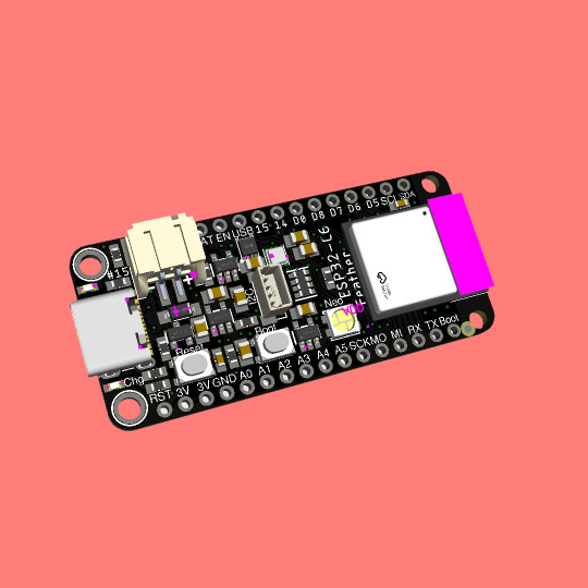
Coming soon - This ESP32-C6 feather is a Matter of fact
ESP32-C6 (https://www.adafruit.com/product/5672) is Espressif’s first Wi-Fi 6 SoC integrating 2.4 GHz Wi-Fi 6, Bluetooth 5 (LE) and the 802.15.4 protocol. It brings the goodness you know from the low-cost C3 series (https://www.adafruit.com/product/5337) and improves it with Zigbee/802.15.4 at 2.4Ghz. That means it could make for great Matter (https://csa-iot.org/all-solutions/matter/) development hardware!
We took our Feather ESP32-S2 (https://www.adafruit.com/product/5000) and swapped out the 'S2 for a C6. Plus some re-routing and here's what we've got: a C6 Feather with lots of GPIO, lipoly charging and monitoring with the MAX17048, (https://www.adafruit.com/product/5580) NeoPixel, I2C Stemma QT port, and a second low-quiescent LDO for disabling the I2C and NeoPixel when we want ultra-low power usage. We also tossed a BME280 (https://www.adafruit.com/product/2652) on there, so you could use it immediately as a low power temp/hum/pressure sensor.
#esp32-c6#wifi-6#bluetooth-5#zigbee#matter-protocol#feather-board#gpio#lipoly-charging#i2c-stemma-qt#bme280-sensor
4 notes
·
View notes
Text
Mastering Embedded Systems: A Comprehensive Online Course Overview
Embarking on the journey to master embedded systems can open doors to exciting career opportunities and allow you to contribute to innovative technologies shaping our world. With the convenience and flexibility of online learning, you can now access comprehensive courses that delve deep into the intricacies of embedded systems. In this blog, we'll provide an overview of what to expect from a comprehensive online course in embedded systems, guiding you through the path to mastering this dynamic field.
Understanding Embedded Systems
Before diving into the specifics of an online course, let's briefly recap what embedded systems are. Embedded systems are specialized computing systems designed to perform specific tasks within larger systems or devices. They are ubiquitous in modern technology, powering everything from smartphones and smart appliances to automobiles and industrial machinery.
The Importance of a Comprehensive Course
A comprehensive online course in embedded systems goes beyond surface-level knowledge, providing you with a deep understanding of the underlying principles and practical skills needed to excel in this field. Such a course covers a wide range of topics, including:
Embedded Hardware Design: Understanding the architecture and components of embedded systems, including microcontrollers, sensors, and actuators.
Microcontroller Programming: Learning programming languages such as C and assembly language to write code for embedded systems.
Real-Time Operating Systems (RTOS): Exploring the concepts of multitasking, scheduling, and resource management in real-time embedded systems.
Embedded Software Development: Developing software applications for embedded systems, including device drivers, firmware, and middleware.
Communication Protocols: Understanding protocols such as UART, SPI, I2C, Ethernet, and CAN bus for inter-device communication.
Embedded System Debugging and Testing: Learning techniques and tools for debugging, testing, and troubleshooting embedded systems.
Course Format and Delivery
A comprehensive online course in embedded systems typically offers a variety of learning resources and formats to cater to different learning styles. These may include:
Video Lectures: Engaging video lectures presented by experienced instructors, covering key concepts and practical demonstrations.
Interactive Tutorials: Hands-on tutorials and exercises to reinforce learning and apply theoretical concepts to real-world scenarios.
Practical Projects: Opportunities to work on real-world projects, designing and implementing embedded systems solutions from start to finish.
Quizzes and Assessments: Regular quizzes and assessments to gauge your understanding of the material and track your progress.
Discussion Forums: Online forums for asking questions, sharing insights, and collaborating with fellow students and instructors.
Instructor Expertise and Support
One of the key factors that distinguish a comprehensive online course is the expertise and support provided by the instructors. Look for courses taught by experienced professionals with a deep understanding of embedded systems and relevant industry experience. Instructors should be accessible and responsive, providing guidance and support throughout your learning journey.
Student Success and Testimonials
Before enrolling in an online course, take the time to research student success stories and testimonials. Look for reviews and testimonials from past students who have completed the course and achieved success in their careers. Positive feedback and success stories can provide valuable insights into the quality and effectiveness of the course.
Conclusion
Mastering embedded systems requires dedication, commitment, and access to comprehensive learning resources. With a comprehensive embedded systems course online, you can gain the knowledge, skills, and confidence needed to excel in this dynamic field. By choosing a course that covers a wide range of topics, offers diverse learning formats, is taught by experienced instructors, and has a track record of student success, you'll be well on your way to mastering embedded systems and unlocking endless possibilities in your career.
0 notes
Text
Understanding Serial Peripheral Interface Communication Protocol
In this article we will learn in depth about the Serial Peripheral interface which is among the widely used communication protocol in Embedded and IOT world.
What is Serial Peripheral Interface - SPI?
SPI is a synchronous serial communication protocol that enables communication between microcontrollers, sensors, memory devices, and other peripheral devices. It allows for full-duplex communication, meaning data can be sent and received simultaneously.
Serial Peripheral Interface (SPI) offers advantages such as high-speed data transfer, simplicity, and versatility.
The serial peripheral interface (SPI) is a communication interaction protocol used to send data between multiple IoT Devices. The Serial Peripheral Interface (SPI) offers data exchange among multiple devices through a master-slave configuration. In SPI the master device begins communication, by sending action bits to the slave devices. In SPI protocol one device serves as the master, with the rest acting as slaves. These modules operate synchronously and SPI ensures simultaneous transmission and reception of data at high speeds. SPI proves efficient for inter-device communication, offering higher data transfer rates compared to alternative interfaces. Its ability to handle bidirectional data flow concurrently enhances efficiency. However, SPI requires more signal lines compared to alternative protocols.
Sample ESP32 code to integrate BME280 (Pressure, Temperature, Humidity) SPI Sensor using Adafruit_BME280 library:
/*
Rui Santos
Complete project details at https://RandomNerdTutorials.com/esp32-spi-communication-arduino/
Based on the Adafruit_BME280_Library example: https://github.com/adafruit/Adafruit_BME280_Library/blob/master/examples/bme280test/bme280test.ino
Permission is hereby granted, free of charge, to any person obtaining a copy
of this software and associated documentation files.
The above copyright notice and this permission notice shall be included in all
copies or substantial portions of the Software.
*/
#include <Wire.h>
#include <Adafruit_Sensor.h>
#include <Adafruit_BME280.h>
#include <SPI.h>
#define BME_SCK 25
#define BME_MISO 32
#define BME_MOSI 26
#define BME_CS 33
#define SEALEVELPRESSURE_HPA (1013.25)
//Adafruit_BME280 bme; // I2C
//Adafruit_BME280 bme(BME_CS); // hardware SPI
Adafruit_BME280 bme(BME_CS, BME_MOSI, BME_MISO, BME_SCK); // software SPI
unsigned long delayTime;
void setup() {
Serial.begin(9600);
Serial.println(F("BME280 test"));
bool status;
// default settings
// (you can also pass in a Wire library object like &Wire2)
status = bme.begin();
if (!status) {
Serial.println("Could not find a valid BME280 sensor, check wiring!");
while (1);
}
Serial.println("-- Default Test --");
delayTime = 1000;
Serial.println();
}
void loop() {
printValues();
delay(delayTime);
}
void printValues() {
Serial.print("Temperature = ");
Serial.print(bme.readTemperature());
Serial.println(" *C");
// Convert temperature to Fahrenheit
/*Serial.print("Temperature = ");
Serial.print(1.8 * bme.readTemperature() + 32);
Serial.println(" *F");*/
Serial.print("Pressure = ");
Serial.print(bme.readPressure() / 100.0F);
Serial.println(" hPa");
Serial.print("Approx. Altitude = ");
Serial.print(bme.readAltitude(SEALEVELPRESSURE_HPA));
Serial.println(" m");
Serial.print("Humidity = ");
Serial.print(bme.readHumidity());
Serial.println(" %");
Serial.println();
}
Key Features of SPI
Full-Duplex Communication: SPI allows simultaneous data transmission and reception between the master and slave devices.
Master-Slave Architecture: One master device controls the communication and initiates data transfer to one or more slave devices.
Synchronous Communication: Data transfer in SPI is synchronized with a clock signal generated by the master device.
Variable Data Frame Format: SPI supports variable data frame formats, allowing flexibility in data transmission.
High-Speed Communication: SPI operates at high speeds, making it suitable for applications requiring rapid data transfer.
Advantages
No need for start and stop bits, providing continuous streaming of data without interruptions.
Higher data transfer rates compared to I2C (almost twice as fast).
Absence of a complex slave addressing system, unlike I2C.
Dedicated MISO and MOSI lines enabling simultaneous data transmission and reception.
Disadvantages
Requires four wires for communication which increase the circuit size
Lacks acknowledgment of successful data reception (unlike I2C).
Absence of error-checking mechanisms such as parity bit in UART.
Applications of SPI
Interfacing with sensors such as accelerometers, gyroscopes, and temperature sensors.
Memory devices like EEPROMs, flash memory, and SD cards.
Communication between microcontrollers and peripheral devices.
Display interfaces in TFT LCD displays and OLED displays.
Networking peripherals such as Ethernet controllers and Wi-Fi modules.
Conclusion
Serial Peripheral Interface (SPI) is a versatile communication protocol widely used in embedded systems and IOT applications for its simplicity, high-speed data transfer, and flexibility. Understanding the fundamentals of SPI, its protocol sequence, applications, and best practices for implementation is essential for engineers and developers working on embedded systems projects. By mastering SPI communication, you can efficiently interface with a wide range of peripheral devices like displays, sensors, modules, microcontrollers and unleash the full potential of your embedded systems designs.
If you’re an Embedded Developer and looking to implement SPI protocol in your project then Campus Component is there for you to assist you integrating SPI successfully in your project. We are the best electronics suppliers that supply all types of SPI devices with end-to-end support. Visit Campus Component now.
0 notes
Text
What are key components and techniques of embedded systems?
Embedded systems are specialized computing systems designed to perform specific tasks within a larger system. They consist of both hardware and software components, working together to ensure functionality, efficiency, and reliability.
Key Components:
Microcontroller/Microprocessor: The central processing unit (CPU) manages all computations and controls the embedded system. Microcontrollers integrate peripherals like memory and I/O ports, making them ideal for compact designs.
Memory: Embedded systems use ROM for storing firmware and RAM for temporary data storage during operation.
Sensors and Actuators: Sensors gather input from the environment, while actuators convert digital signals into physical actions.
Power Supply: Ensures consistent and reliable energy for the system, critical for uninterrupted operation.
Communication Interfaces: Protocols like UART, SPI, and I2C facilitate data exchange between components or with external devices.
Key Techniques:
Real-Time Operating Systems (RTOS): Manage tasks with precise timing, essential for systems requiring high responsiveness, such as medical devices or automotive controls.
Power Management: Techniques like sleep modes and dynamic voltage scaling optimize energy consumption, particularly important in battery-operated devices.
Error Handling: Methods like watchdog timers and redundancy ensure system reliability under abnormal conditions.
Code Optimization: Embedded systems have resource constraints, so developers use efficient coding practices to minimize memory and power usage.
Debugging Tools: Techniques like in-circuit emulators (ICE) and logic analyzers help identify and resolve issues during development.
Professionals aiming to excel in this field can benefit greatly from structured learning. Enrolling in an embedded system certification course provides practical skills and theoretical knowledge, bridging the gap between academic concepts and industry requirements.
0 notes