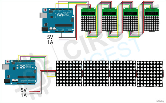
#led control with arduino
Explore tagged Tumblr posts
Visit Tumblr Blog
Explore Tumblr blogs with no restrictions, modern design and the best experience.
Last Seen Tumblr Blogs


Fun Fact
Tumblr was created by web developers David Karp and Marco Arment.
Text
youtube
Push Button Multi LEDs Controller - Switch Case Vs Array Arduino Programming for Beginners Online Arduino Simulator Virtual Breadboard basic sketch examples: Programming and write Arduino UNO sketch with ezButton Arduino library for controlling LEDs toggle switch ON/OFF with a push button.
#programming#how to#simulator#wokwi#arduino#tutorials#Push Button#LEDs Controller#Virtual Breadboard#Youtube
0 notes
Text


M T C 2 4 0 1
Commissioned storage cabinet inspired by Magnetic Tape Units, specifically the IBM 2401 (1964)
The tape mechanism is decoration only and does not function. DC motors, blinking LEDs and audio streaming(vintage computer sound samples) are run by an Arduino board inside the control unit on top of the cabinet.
Source: https://www.lovehulten.com/
124 notes
·
View notes
Text

Puppies Puppies (Jade Guanaro Kuriki-Olivo) World Population Clock (Horloge Mondiale de la Population), 2023 Dot matrix LED panels, Arduino micro controller
13 notes
·
View notes
Text
Captain Curly's Cake. Oil on acrylic panel with backlight.
Still images below cut.


I've got an arduino promicro hooked up to some led strips inside the enclosure to control the lighting.
25 notes
·
View notes
Text

Festival of Lights - 1.28" Round TFT display 🔵🎉
To wrap up this year, we're doing 8 days of light-filled designs. We started with the Sparkle Motion Mini
which can drive thousands of shimmering RGB LEDs. Then, we did the Sparkle Motion stick, a USB-pluggable version. Today, we're taking a detour into some very old designs we've been meaning to do for years! Starting with this 1.28" round TFT display that has 240x240 shiny IPS pixels. We have a round outline, two mounting holes, breakout pads for all the control and power pins, plus an EYESPI connector
#festivaloflights#tftdisplay#rounddisplay#leddesign#sparklemotion#techart#innovation#rgbleds#sparklemotionmini#sparklemotionstick#adafruit#ipsdisplay#makersgonnamake#techgadgets#electronicsprojects#creativeengineering#roundtft#diytech#techcreativity#hardwaredesign#eyespi#electronicsengineering#pixelart#technologicalart#engineeringdesign#makercommunity#ledprojects#lightdesign#diyelectronics#futuretech
12 notes
·
View notes
Text
Just finished making a circuit diagram in Fritzing and I don’t know if I’m doing it wrong or something because it was pretty annoying to put together.
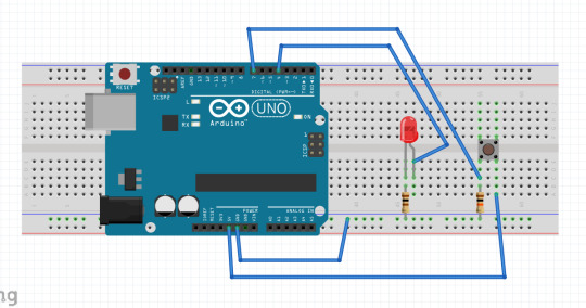
This is the diagram that I made, really simple yet it took me a while. It wasn’t hard to find the parts that I wanted to add, but the controls for moving them around were simply annoying to use. Not to mention the weird zoom in/out controls. For some reason I couldn’t use the touchpad to zoom out? Only zoom in? Idk, I’ll make another post if it gets better with use.
If you want to see my circuits homework for whatever reason, it’s under the cut.
Here’s a video of the circuit in question working in real life. The goal is to make the light turn off for two seconds only after the button is released. LED is in series with a 100 ohm resistor just to make sure it doesn’t burn out (and to make it a little less painful on the eyes). Button is wired in a pulldown resistor setup (the detector is after the button) with a 10k resistor. This is so that when the button is pressed, the value reads as high.
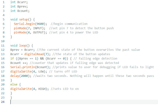
This is the C++ code that is running on the Arduino uno. It just uses an If else statement to control the state of the LED according to the button. Read the comments (grey text) for a short explanation of what each line does. If you want a more in depth explanation uhh message me I guess.
#pretty simple circuit but it touches on a lot of topics#idk it's simple to me#stemblr#arduino#electrical wiring#c++#c++ programming#fritzing#circuit diagram#unironically my homework#the documentation takes more time than anything else :/
9 notes
·
View notes
Text
On one hand, I hate my robotics teacher for teaching us the same lesson on python loops we've been learning for half the damn school year, then expecting us to make an innovative robot in 3 weeks when arduino is based on C++.
I was gonna counter that with something else, but as I wrote it I realized just how stupid it actually is. Fuck it. Venting time.
NO CUZ I CAN'T UNDERSTAND THIS GUY. WDYM "Programming's easy! You learn the basics, and from there you make your own solutions." ??? That's not verbatim but. STILL.
I'll give him a bit of credit, he taught us the basics of arduino. The proper syntax, loops, variables, functions, motor control, sensors, etc. But for god's sake, that limited pool of knowledge can only get you enough to make a mini car! It would've been nice to learn about fading LEDs, integer overflow, pointers vs the actual value in a variable, OR EVEN WHAT DOCUMENTATION IS. YEAH. DOCUMENTATION. THE LITERAL OFFICIAL EXPLANATION FOR KEY FEATURES IN PROGRAMMING LANGUAGES.
But suddenly its OUR fault our code doesn't work because "I taught you the basics. If you don't understand, that means you're not listening during my classes." MAYBE IF YOU STOPPED TEACHING US WHAT A FUCKING FOR LOOP IS, WE'D HAVE A REASON TO LISTEN. Majority of my understanding of robotics are a product of self study and receiving help from my family and their long list of IT contacts.
Not only that, HE is the one that approves of our robotics projects. If YOUR students can't complete the project YOU personally approved of, isn't that an error on your part? You should know what your students are capable of making. You should know because they should only know WHAT YOU TEACH THEM. So surprise surprise when your students feel like they're forced to hire people to do their projects, all because of your failure to teach them the skills they needed to do it themselves.
The only people getting a passing grade in this class are gonna be those that are either rich or have a lot of contacts. What a fucking joke.
And don't be mistaken, this is NOT the complaint of someone who doesn't understand programming. I consistently get 90% and above on his exams and do coding for fun. I'm complaining on behalf of my classmates who weren't as lucky as me, in that I have way more people to ask help from.
"100% working by this week" my ass. Actually teach us something relevant for once.
#dumb ramblings#vent post#ough#for the record i do like coding in python#i prefer it over C++ actually#But none of our projects use python#so I don't know what's going on in my teacher's head...
4 notes
·
View notes
Text
Talerzowość sekwencji
y = [[(button)], [(potentiometer)], [(LED)]]; table_of_contents;
x = [(voltage]), [(Ohm), (resistance)]; table_of_proof;
//
y = [(button), (potentiometer), [(LED)]; table_of_semimassels;
x = [(voltage]), [(Ohm), (resistance)] table_of_semiproofs;
// { resistantio_tool = potentiometer(potentio_L, potentio_M, potentio_L) +
[radiato_tool]
(resistantio_tool)
5V -> LED -> potentio_L [potentio_tool] + (potentiometer)
}
{{}} optimizer tool of affective dogma, lol?
///// Test-Case Rezultado. Kolizja sekwencji. + stepper motor *A* serwomechanism;;
Arduino vs bateria
Rozszczelnienie sekwencjonometrualne
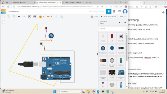
^^ Zadanie: Układ oraz kod składający się z Potencjometru, przycisku i diody. Dioda zapala się z wartością zadaną na potencjometrze po wciśnięciu przycisku.
{{{}}} sektor "upper" ; sektor "lower"
konieczność zastosowań macierzy przy skrzyżowaniach [*których*]
Kolejność podłączeń czy sekwencji.
Konieczność prądu i konieczność uziemienia{ a stechiometria kolimatyczna quote un quote.
Transformacja Fermata (?) : "chodzi o całkowanie przestępne", tj. subweniencyjny tor kolima(torowy).
Słup syntezy i diegezy ciało-czucia-obrazu.
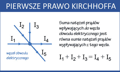
} co z: Prawo Kirchhoffa


vv Zadanie. Wykorzystując potencjometr oraz mapowanie wartości stwórz.... {obrotem serwomechanizmu...} >Incredible Hillar-Jofo<
>Grand Densor{3}< [rzędonumeracja (układu_całkowe)]
i.e = "stechiometry_radiance" possible tools: {[double-check (cathode, anode) OR ((cathode), (anode));
potentiometer -> resistor -> [button_U_R(red)] -> {X *OR* z/y *OR* xyz} -> [button_L_R]
2 notes
·
View notes
Text


GUESS WHO FOUND AN ORGAN FOREVER AGO?
Found an organ (psure it's an AceTone B-422) on the side of the road one day while some guy was clearing out his dad's house, and managed to get this organ for free. Dude said he didn't get a chance to try it out, nabbed it anyway and stuffed it in my room.
Turns out, it doesn't work.
Turns out, it has a bunch of built in features that DO work.
There's a built in vibrato, a built in reverb, a built in Rhythm Ace Drum Machine, and a God Damn Leslie-branded rotary speaker built in. The drum machine, speaker, and rotary speaker all for sure work, and since it's a 60s organ that reverb is pmuch guaranteed to be a spring tank, which is easy to repurpose. The vibrato would be cool to mess with, too. Lastly, there's a "Brilliance" switch which I'm really curious about.
As for the rest of the organ, I have a bunch of options:
1. I rip out all the keys, replace them with modern midi controllers, and turn the whole thing into a custom recording station. Problem is, the two keyboards are 44 keys each, which is pretty rare for midi controllers. They're also bigger keys than normal, so maybe there's a way to make them work, but that also makes the depth of the keys an issue I'll have to tackle. It also means the 13 bass pedals would be useless.
2. I get 1-4 Arduino boards, and rewire the keyboards so I have 2 44-key controllers, 13-pedal controller, and if I wanna get crazy with it the swell pedal and whatever other knobs I want for midi controls. Problem is, I know nothing about Arduino or digital midi, and I'm already diving headfirst into several unfamiliar disciplines for this project as is. DOUBLE problem is, from what I can tell it would be difficult if not impossible to make the original keybeds velocity sensitive. Triple problem is, if I do decide to toss the key beds, I can't go back and Arduino it up later. I'm not gonna be able to hold onto those parts, and there's no way I could justify having a whole second house organ just to reattempt it.
3. I cut my losses, rip out the relevant electronics, and toss the rest
If I go with either of the first two (read: fun) options, it's also worth considering all the space around the keys, where I can theoretically add whatever. I've tossed around the idea of putting a 2x4 group of drum pads, maybe some knobs or even a ribbon controller somewhere. I could even put a screen there, either with real time feedback or built in synths or digital effects (maybe a raspberry pi or small computer affordable to run soundfonts or even VSTi's natively; imagine having a DIY touch screen with drawbars next to the keyboard to adjust settings, that'd be sick)
And none of that takes into consideration the multitude of cosmetic modification options possible; Paint, veneer, upholstery, LEDs, lights, VU meters, metalwork, leather, the list goes on.
I've got a bunch of ideas and I'm in the process of getting the tools together to move forward with this project.
I'm sure I can also upgrade stuff in the future.
But I'm seriously considering turning this thing into the ultimate keyboard performance desk, both for YouTube stuff as well as live (since, theoretically, it'll be a LOT lighter once the speakers and motor(s) are pulled out)
If anyone has experience with doing any of this sort of thing, I'd love to pick your brains for more info on all this stuff. Working on researching for a YouTube video about the project, including a history of the Ace Tone company that made it (with probably too much emphasis on it being founded by the same dude who founded Roland several years later).
It's a big project, but I think it'd be worth it. I'm more excited about this than I have been about virtually anything else in years.
#organ#keyboards#midi#diy#prog rock#midi controller#synths#synthesizer#AceTone#Roland#music#instrument#piano#leslie#rotary cabinet
4 notes
·
View notes
Text
Top 10 Projects for BE Electrical Engineering Students
Embarking on a Bachelor of Engineering (BE) in Electrical Engineering opens up a world of innovation and creativity. One of the best ways to apply theoretical knowledge is through practical projects that not only enhance your skills but also boost your resume. Here are the top 10 projects for BE Electrical Engineering students, designed to challenge you and showcase your talents.
1. Smart Home Automation System
Overview: Develop a system that allows users to control home appliances remotely using a smartphone app or voice commands.
Key Components:
Microcontroller (Arduino or Raspberry Pi)
Wi-Fi or Bluetooth module
Sensors (temperature, motion, light)
Learning Outcome: Understand IoT concepts and the integration of hardware and software.
2. Solar Power Generation System
Overview: Create a solar panel system that converts sunlight into electricity, suitable for powering small devices or homes.
Key Components:
Solar panels
Charge controller
Inverter
Battery storage
Learning Outcome: Gain insights into renewable energy sources and energy conversion.
3. Automated Irrigation System
Overview: Design a system that automates the watering of plants based on soil moisture levels.
Key Components:
Soil moisture sensor
Water pump
Microcontroller
Relay module
Learning Outcome: Learn about sensor integration and automation in agriculture.
4. Electric Vehicle Charging Station
Overview: Build a prototype for an electric vehicle (EV) charging station that monitors and controls charging processes.
Key Components:
Power electronics (rectifier, inverter)
Microcontroller
LCD display
Safety features (fuses, circuit breakers)
Learning Outcome: Explore the fundamentals of electric vehicles and charging technologies.
5. Gesture-Controlled Robot
Overview: Develop a robot that can be controlled using hand gestures via sensors or cameras.
Key Components:
Microcontroller (Arduino)
Motors and wheels
Ultrasonic or infrared sensors
Gesture recognition module
Learning Outcome: Understand robotics, programming, and sensor technologies.
6. Power Factor Correction System
Overview: Create a system that improves the power factor in electrical circuits to enhance efficiency.
Key Components:
Capacitors
Microcontroller
Current and voltage sensors
Relay for switching
Learning Outcome: Learn about power quality and its importance in electrical systems.
7. Wireless Power Transmission
Overview: Experiment with transmitting power wirelessly over short distances.
Key Components:
Resonant inductive coupling setup
Power source
Load (LED, small motor)
Learning Outcome: Explore concepts of electromagnetic fields and energy transfer.
8. Voice-Controlled Home Assistant
Overview: Build a home assistant that can respond to voice commands to control devices or provide information.
Key Components:
Microcontroller (Raspberry Pi preferred)
Voice recognition module
Wi-Fi module
Connected devices (lights, speakers)
Learning Outcome: Gain experience in natural language processing and AI integration.
9. Traffic Light Control System Using Microcontroller
Overview: Design a smart traffic light system that optimizes traffic flow based on real-time data.
Key Components:
Microcontroller (Arduino)
LED lights
Sensors (for vehicle detection)
Timer module
Learning Outcome: Understand traffic management systems and embedded programming.
10. Data Acquisition System
Overview: Develop a system that collects and analyzes data from various sensors (temperature, humidity, etc.).
Key Components:
Microcontroller (Arduino or Raspberry Pi)
Multiple sensors
Data logging software
Display (LCD or web interface)
Learning Outcome: Learn about data collection, processing, and analysis.
Conclusion
Engaging in these projects not only enhances your practical skills but also reinforces your theoretical knowledge. Whether you aim to develop sustainable technologies, innovate in robotics, or contribute to smart cities, these projects can serve as stepping stones in your journey as an electrical engineer. Choose a project that aligns with your interests, and don’t hesitate to seek guidance from your professors and peers. Happy engineering!
5 notes
·
View notes
Text
Design Wanted
"The studio’s trajectory took a significant turn around 2012 when they embraced physical computing. Their partnership with Arduino’s founder, Massimo Banzi, led them to experiment with open-source technologies, resulting in a series of prototypes, including lamps and gesture-controlled speakers that redefined conventional electronics. "
2 notes
·
View notes
Text
The PAJ7620 is a highly capable gesture recognition sensor. It can detect a wide range of gestures such as up, down, left, right, forward, backward, and more. The sensor uses an array of infrared LEDs and a photodiode array to detect motion in its field of view. It communicates with a microcontroller (like Arduino) over the I2C interface, making it a versatile option for many gesture-controlled applications.
1 note
·
View note
Text
Devlog 1 (1/25/24): Why This Is Pointless
In my intro post, I mentioned how it would be much easier to map the 12 chromatic notes of Western music to the 3 action buttons and 8 directions of Undertale, and how I won't be doing that for purely aesthetic reasons. I also want to mention why everything I'm doing to my violin is completely stupid.
If you want to follow in my footsteps, you shouldn't do it the way I'm doing it. You probably can't.
My violin is a Yamaha EV-205 five-string electric from the late aughts/early 10's. I recently learned that this violin is no longer in production, so there's no way your standard Joe Schmoe can pick up this tutorial, nor would they want to if they were in the market for an electric violin, because they already sell electric violins that are MIDI controller enabled. You should buy that and follow the software specs of CZR drums and their MIDI-to-controller software partner/whatever. I simply do not want to spend more money on an electric violin when I already have one with the right hardware (individual pickups for each of the five strings). So I will be voiding the warranty that likely no longer exists and busting open my violin to see what I can patch together.

When I busted this component (pictured above) open I immediately found a not-so-complex PCB where I could locate each of the individual string inputs. I have yet to see whether those ports will give me the inputs I need - golly, I have yet to learn how to solder enough to access those ports!! - but the visibility gives me hope. it doesn't look hard, especially for someone who has been low-key interested in soldering for like 15 years (since my Pokemon Gold copy's battery died and I learned the ways to replace it) but I can't say I know exactly what data flows through that part of the circuit and how easy it would be to extract and manipulate.
I've done a lot of research into what I would need to take analog audio signal(s) and transform them into MIDI or some other binary/digital data. The first thing I found was an Arduino library, so I knew this wouldn't be hard. I only have one Arduino (knock-off) and I didn't like the idea of buying four more (one for each string) to get the MIDI values when I would probably be connected to a computer the whole time no matter what.
This led me to where I'm sitting pretty right now, at a Python library (Python being my favorite language) that uses its GitHub .md file to explain why Markov chains are important. Reader, do you know how much I love Markov chains? Did you know that in my sophomore year of college I created a musical AI by programming Markov chains in Python??? How is it that all of my interests loop in upon each other in the same way that my first and only job out of college involved natural language processing in Python just like my senior project where I did language analysis on okcupid profiles???? Is time in fact a flat circle? I don't have time to think about this because I want to program violin to play undertale pleas
Where I'll be starting is with this library and with monophonic input (one note at a time rather than interpreting multiple notes at once e.g. multiple strings played simultaneously) to make a controller of any kind work. But I have a lot of reading to do to see how Markov chains are involved. With it being both Python and linear algebra, I have the capacity to adjust the code to do whatever I want it to do. Given this insane opportunity I can't not do all the research possible to finetune things to my precise desires. If I were satisfied with "good enough", I would be playing monophonic input the whole way through. Let's go insane, boys.
5 notes
·
View notes
Text
DeerHead EMC-V1 baby pictures.. She doesn't even have all of her leg servos yet 🥺 (EMC stands for "Electro-Mechanical Chihuahua"!)

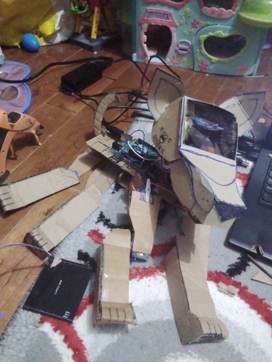

Her snout is a bit huge for this first run, but really this is just a draft while the 3D printer is broken; the LED matrix in her head was also defective right out of the package, as it turns out; so because it's also a little heavy, I probably won't end up using it! That's okay because atleast for the Arduino Uno, running both 15 servoes and the 64 pixel screen animations at once could be a bit much! I'm thinking of getting the hardware up and at 'em first, and making sure that I can program it to say, do a little dance for now to show that I'm up for the challenge of animating servoes with this driver library (right now I'm just testing with a live servo control program), and then I want to upgrade to a Raspberry Pi brain so that I can start giving her autonomy! When I do that, I'm going to atleast want two buttons; a back and head button to sense affection and love! Or scoulding with a tap on the head, but that might be much to program for something I'd never really need to do with a robot I programmed XD unless it ended up being more autonomous than I'm realisitcally imagining it being! I'll also want a gyro sensor, so that she'll be able to tell if she's fallen over (maybe combined with soft buttons on her front paws sensing that they aren't touching the ground), and self-right! She will also have a distance sensor on her chest to avoid bumping into things, and for a general sense of depth; and beside that, a microphone (connected to a voice recognition module? I feel like Raspberry Pi wouldn't need that, I haven't looked into it though), to understand voice commands.. Or just "I love you" whilst receiving cuddles 😄 and of course, there would be a speaker, likely in the back of the head or also near the distance sensor depending on the size; for this maybe I can use some old furby boom parts I have laying around 😆 I'd probably need a module for the speaker though, so the Pi knows it's a speaker, and that'd probably come with another speaker.. And to power it all? A six volt LIPO battery! Or would six volts be anywhere near enough for all that combined with running the programming of the robot? Such I'd have to research lol, but furthermore.. I welcome EMC-V1 to the world!!! And tomorrow my new servoes will come in, hopefully she'll be able to walk too by then 😄
5 notes
·
View notes
Text
Terry and Julia Group Project 1
Video Walkthrough LinkImage of the Project
The last two weeks Terry and I worked on our project called “Hit the Dick” (see video walkthrough above).
Aim of the Game:Each player has one strap-on game controller containing an Airpump, a rgb-LED, as well as a capacitive touch sensor attached to the tip. The game starts by randomly choosing one player whose strap-on will light up green after a random delay. That player has to hit the other players strap on within 3 seconds. If the player succeeds in hitting it before the opponent has dodged, the players starp-on will fill with a little bit of air. Players then take turn until one of the players has gained 5 points.
Hardware:LED: serves to indicate the current state of the game: Who is hitting, who has to dodge. AirPump that fills Silicone strap-on with air: Serves as a funny way to indicate the players points. The higher the Point count, the “higher” the strap-on will be (lol).Capacitive Touch Sensor: detects the slapping
Process:Terry and I ran into a few difficulties during building this project: Here are some interesting findings summed up:
Building the silicone strap-ons: It was really challenging to create 3D printed negatives that would serve as the mold for the strap-ons because we needed to make sure we had enough hallow space for the air to fill.
Getting the Airpumps to work: After some testing, we realized that the Arduino does not have enough power to power the Airpumps using the GPIO pins. Hence, we ended up using a Relay connected to an external 5V 2A power source!
3 notes
·
View notes
Text
WHAT IS NEW?
🎧 TLV320DAC3100: Tiny I2S DAC, huge sound! 🖱️ USB Mouse: Classic 2-button + wheel control. ⚡ Pi PoE+: Power & data over 1 cable. 🌈 Plasma 2350 W: Wireless LED driver fun. 🖼️ Inky Frame 7.3": Big eInk display, built-in Pico W. 📱 ESP32-S3 TFT: Reversed display, w.FL WiFi.
https://adafruit.com/new
#tlv320dac3100#i2sdac#usbmouse#pioeplus#poweroverethernet#plasma2350w#wirelessled#inkyframe#einkdisplay#picow#esp32s3#tftdisplay#reverseddisplay#embeddedtech#microcontrollers#makergear#engineering#programming#linux#python#java#software engineering#coding#techrelease#newtech#hardwarehacks#diyprojects#raspberrypi#electronicsfun#gadgetdrop
7 notes
·
View notes