#microcontroller based induction motor speed control
Explore tagged Tumblr posts
Visit Tumblr Blog
Explore Tumblr blogs with no restrictions, modern design and the best experience.
Last Seen Tumblr Blogs


Fun Fact
The most popular pages on Tumblr are about Minecraft, GIFs, and David J. Peterson.
Text
Reference Design For Vacuum Cleaner

A vacuum cleaner design integrates a microcontroller, advanced infrared functionality, and intelligent suction management.
Vacuum Cleaner Circuit Board Today’s vacuum cleaner is an essential home tool. The upright and canister models are its two primary forms. While upright vacuums are popular in the US and UK, canister types dominate the European market. To simplify the design process NXP Semiconductor has launched the reference design for a vacuum cleaner that uses a universal motor, meaning that the motor can operate from an ac or dc supply. Vacuum cleaner motors can reach speeds of up to 30,000 RPMs. This rapid operation is essential to produce potent suction with a compact fan. In contrast, an induction motor’s speed is capped at 3600 RPMs. The reference design is based on the HC908KX8 microcontroller unit (MCU), which produces the triac drive waveform and regulates the motor’s speed. Microcontrollers enhance these advanced models by incorporating features like infrared or wired remote controls, status LED indicators, and automated suction management. A potentiometer adjusts the motor speed, with the MCU gauging the potentiometer through an analogue-to-digital converter (ADC) port pin. Current injection into the MCU is controlled using a high-value resistor. To drive the triac directly, four-port pins provide adequate sink current. A charge pump power supply powers the MCU and the trial’s drive current. This power supply method is effective only up to roughly 20 mA, with its supply current determined by the AC line capacitor’s size. However, a basic charge pump power supply needs the current capacity to power status LEDs. To reduce the triac drive current, a sensitive gate triac can be employed. The design of the vacuum cleaner incorporates phase angle control, which entails delivering only a section of the AC waveform to the load. The primary function of the phase angle control software is to generate the trigger pulse for the triac. The software has been developed for basic vacuum cleaner universal motor control. The design also features an internal oscillator and a small 16-pin package. The software is compatible with the internal oscillator or other low-cost RC oscillators. The reference design has eight Kbytes of FLASH memory, ample for a modest program. The phase angle control software occupies just around 1.2 Kbytes of this memory. The peak current of the vacuum cleaner motor design is approximately 40 amps. NXP has tested this reference design. It comes with a Bill of Material (BOM), schematics, etc. You can find additional data about the reference design on the company’s website. To read more about this reference design, click here. Source link Read the full article
0 notes
Text
PROJECT TOPIC- CONSTRUCTION OF A MICROCONTROLLER BASED T-JUNCTION TRAFFIC LIGHT CONTROLLER
PROJECT TOPIC- CONSTRUCTION OF A MICROCONTROLLER BASED T-JUNCTION TRAFFIC LIGHT CONTROLLER
PROJECT TOPIC- CONSTRUCTION OF A MICROCONTROLLER BASED T-JUNCTION TRAFFIC LIGHT CONTROLLER ABSTRACT
T-junction traffic light controller is such a device that will play a significant role in controlling traffic at junctions, to ease the expected increased rush at such junctions and reduce to minimum disorderliness that may arise, as well as allowing the pedestrians a right of the way at…
View On WordPress
#a microcontroller based power management system#microcontroller based anesthesia machine#microcontroller based applied digital control#microcontroller based applied digital control pdf#microcontroller based automated irrigation system#microcontroller based baby incubator using sensors#microcontroller based blood pressure monitoring system#microcontroller based diode and bipolar junction transistor (bjt) tester#microcontroller based electronic projects#microcontroller based function generator#microcontroller based generator/alternator control and monitoring system#microcontroller based greenhouse project#microcontroller based home security system with gsm technology#microcontroller based induction motor speed control#microcontroller based projects with circuit diagram
0 notes
Text
youtube
RS-795 PWM dc motor controller test function, how to control dc motor speed by PWM motor controller,How does PWM control speed of RS-775 DC motor, How To Make a PWM DC Motor Speed Controller using the 555 Timer IC, Control the speed of a DC motor without sacrificing torque. This Pulse-Width-Modulation (PWM) DC motor controller can provide up to a maximum continuous current of 5A to your DC motor or other DC load thanks to a digital microcontroller based (PIC) design and highly efficient High-Power MOSFET for cooler operation.Motors RS-775 DC Motor DC 18V 19000RPM speed controller, PWM drive is used with brushed DC motors, the rotor's internal inductance acts as a current filter which is good for the drive circuit.#pwmmotorcontroller,#pwmdcmotorcontroller,#DIYpwmcontroller,#pwndrive,#pwmspeedcontroller,#testdcmotor,#dcmotor,#kegumotor
#pwmmotorcontroller#pwmdcmotorcontroller#DIYpwmcontroller#pwndrive#pwmspeedcontroller#testdcmotor#dcmotor#kegumotor#Youtube
0 notes
Text
Channel Mosfet

MOSFET Tizen deezer 2.
N Channel Mosfet Circuit
P Channel Mosfet Operation
N Channel Mosfet Symbol
ST's P-channel MOSFET portfolio is optimized to meet a broad range of requirements for load switch, linear regulator, automotive applications and specifically designed for portable applications. The MOSFET is another category of field-effect transistor.There are two types of MOSFET, Enhancement mode MOSFET and Depletion mode MOSFET. Major Brands BS250 N-Channel MOSFET Transistor, TO-92, 3 Pin, 5.2 mm H x 4.2 mm W x 4.8 mm L (Pack of 10) 5 $8 79 ($0.88/Transistor). This Article Shows A Detailed And Clear Explanation Of MOSFET Working, Structure, Analysis, Example, Applications, Benefits And Many Others. If you need to switch high current and or high voltage loads with a micro controller you'll need to use some type of transistor. I'm going to be covering how to use a MOSFET since it's a better.
The MOSFET is an important element in embedded system design which is used to control the loads as per the requirement. Many of electronic projects developed using MOSFET such as light intensity control, motor control and max generator applications. The MOSFET is a high voltage controlling device provides some key features for circuit designers in terms of their overall performance. This article provides information about different types of MOSFET applications.
MOSFET and Its Applications
The MOSFET (Metal Oxide Semiconductor Field Effect Transistor) transistor is a semiconductor device which is widely used for switching and amplifying electronic signals in the electronic devices.The MOSFET is a three terminal device such as source, gate, and drain. The MOSFET is very far the most common transistor and can be used in both analog and digital ckt.
The MOSFET works by varying the width of a channel along which charge carriers flow (holes and electrons). The charge carriers enter the channel from the source and exits through the drain. The channel width is controlled by the voltage on an electrode is called gate which is located between the source and drain. It is insulated from the channel near an extremely thin layer of metal oxide. There is a different type of MOSFET applications which is used as per the requirement.
Types of MOSFET Devices
The MOSFET is classified into two types such as;
Depletion mode MOSFET
Enhancement mode MOSFET
Depletion Mode: When there is zero voltage on the gate terminal, the channel shows its maximum conductance. As the voltage on the gate is negative or positive, then decreases the channel conductivity.
Depletion Mode MOSFET
Enhancement Mode
When there is no voltage on the gate terminal the device does not conduct. Twitch deezer. More voltage applied on the gate terminal, the device has good conductivity.
Enhance Mode MOSFET
MOSFET Working Principle
The working of MOSFET depends upon the metal oxide capacitor (MOS) that is the main part of the MOSFET. The oxide layer presents among the source and drain terminal. It can be set from p-type to n-type by applying positive or negative gate voltages respectively. When apply the positive gate voltage the holes present under the oxide layer with a repulsive force and holes are pushed downward through the substrate. The deflection region populated by the bound negative charges which are allied with the acceptor atoms.
P- Channel MOSFET
The P-Channel MOSFET consist negative ions so it works with negative voltages. When we apply the negative voltage to gate, the electrons present under the oxide layer through pushed downward into the substrate with a repulsive force. The deflection region populates by the bound positive charges which are allied with the donor atoms. The negative voltage also attracts holes from p+ source and drain region into the channel region.

P-Channel MOSFET
N- Channel MOSFET
When we apply the positive gate voltage the holes present under the oxide layer pushed downward into the substrate with a repulsive force. The deflection region is populated by the bound negative charges which are allied with the acceptor atoms. The positive voltage also attracts electrons from the n+ source and drain regions into the channel. Now, if a voltage is applied among the drain and source the current flows freely between the source and drain and the gate voltage controls the electrons in the channel. In place of positive voltage if we apply a negative voltage (hole) channel will be formed under the oxide layer.
N-Channel MOSFET
MOSFET Applications
The applications of the MOSFET used in various electrical and electronic projects which are designed by using various electrical and electronic components. For better understanding of this concept, here we have explained some projects.
MOSFET Used as a Switch
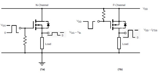
In this circuit, using enhanced mode, a N-channel MOSFET is being used to switch the lamp for ON and OFF. The positive voltage is applied at the gate of the MOSFET and the lamp is ON (VGS =+v) or at the zero voltage level the device turns off (VGS=0). If the resistive load of the lamp was to be replaced by an inductive load and connected to the relay or diode to protect the load. In the above circuit, it is a very simple circuit for switching a resistive load such as LEDs or lamp. But when using MOSFET to switch either inductive load or capacitive load protection is required to contain the MOSFET applications. If we are not giving the protection, then the MOSFET will be damaged. For the MOSFET to operate as an analog switching device, that needs to be switched between its cutoff region where VGS =0 and saturation region where VGS =+v.
Auto Intensity Control of Street Lights using MOSFET
Now-a-days most of lights placed on the highways are done through High Intensity Discharge lamps (HID), whose energy consumption is high. Its intensity cannot be controlled according to the requirement, so there is a need to switch on to an alternative method of lighting system, i.e., to use LEDs. This system is built to overcome the present day drawbacks of HID lamps.
Auto Intensity Control of Street Lights using MOSFET
This project is designed to control the lights automatically on the highways using microprocessor by variants of the clock pulses. In this project, MOSFET plays major role that is used to switch the lamps as per the requirement. The proposed system using a Raspberry Pi board that is a new development board consist a processor to control it. Here we can replace the LEDs in place of HID lamps which are connected to the processor with the help of the MOSFET. The microcontroller release the respective duty cycles, then switch the MOSFET to illuminate the light with bright intensity
Marx Generator Based High Voltage Using MOSFETs
The main concept of this project is to develop a circuit that delivers the output approximately triple to that of the input voltage by Marx generator principle. It is designed to generate high-voltage pulses using a number of capacitors in parallel to charge during the on time, and then connected in series to develop a higher voltage during the off period. If the input voltage applied is around 12v volts DC, then the output voltage is around 36 volts DC.
This system utilizes a 555 timer in astable mode, which delivers the clock pulses to charge the parallel capacitors during on time and the capacitors are brought in a series during the off time through MOSFET switches; and thus, develops a voltage approximately triple to the input voltage but little less, instead of exact 36v due to the voltage drop in the circuit. The output voltage can be measured with the help of the multimeter.
EEPROM based Preset Speed Control of BLDC Motor
The speed control of the BLDC motor is very essential in industries as it is important for many applications such as drilling, spinning and elevator systems. This project is enhanced to control the speed of the BLDC motor by varying the duty cycle.
EEPROM based Preset Speed Control of BLDC Motor
The main intention of this project is to operate a BLDC motor at a particular speed with a predefined voltage . Therefore, the motor remains in an operational state or restarted to operate at the same speed as before by using stored data from an EEPROM.
Before using Praat to do sound analysis, we have to be clear about know that what information we can get from Praat. Table 1 presents some major acoustic variables we usually use to analyze the speech sounds. 49) for visual presentation of the variables. Praat is a free software package used for speech analysis in phonetics. It is designed and continuously developed by Paul Boersma and David Weenink of the University of Amsterdam. It is a flexible tool that offers a broad range of standard and non-standard procedures such as spectrographic analysis, speech synthesis, articulatory synthesis and neural networks. Praat allows you to divide up the sound signal into temporal stretches or intervals, and to assign text or labels to these intervals. It does this by means of what it calls a TextGrid. The basic idea is that one might want to divide a signal into intervals in more than one way. Praat scripts Phonetics Laboratory Scripts and batch processes are a handy way of saving time while performing repetitive operations. In this page we share some of the Praat scripts we use in our Lab. All the scripts include instructions (either at the begining of the file or in the first form of the script). PRAAT is a very flexible tool to do speech analysis. It offers a wide range of standard and non-standard procedures, including spectrographic analysis, articulatory synthesis, and neural networks. This tutorial specifically targets clinicians in the field of communication disorders who want to learn more about the use of PRAAT as part of an. Praat phonetics.
The speed control of the DC motor is achieved by varying the duty cycles (PWM Pulses) from the microcontroller as per the program. The microcontroller receives the percentage of duty cycles stored in the EEPROM from inbuilt switch commands and delivers the desired output to switch the driver IC in order to control the speed of the DC motor. If the power supply is interrupted, the EEPROM retains that information to operate the motor at the same speed as before while the power supply was available.
LDR Based Power Saver for Intensity Controlled Street Light
In the present system, mostly the lightning-up of highways is done through High Intensity Discharge lamps (HID), whose energy consumption is high and there is no specialized mechanism to turn on the Highway light in the evening and switch off in the morning. Recoverit download mac.
LDR Based Power Saver for Intensity Controlled Street Light
N Channel Mosfet Circuit

P Channel Mosfet Operation
Its intensity cannot be controlled according to the requirement, so there is a need to switch to an alternative method of lighting system, i.e., by using LEDs. This system is built to overcome the present day, drawback of HID lamps.
This system demonstrates the usage of LEDs (light emitting diodes) as light source and its variable intensity control, according to the requirement. LEDs consume less power and its life is more, as compared to conventional HID lamps.
The most important and interesting feature is its intensity that can be controlled according to requirement during non-peak hours, which is not feasible in HID lamps. A light sensing device LDR (Light Dependent Resistance) is used to sense the light. Its resistance reduces drastically according to the daylight, which forms as an input signal to the controller . A cluster of LEDs is used to form a street light. The microcontroller contains programmable instructions that controls the intensity of lights based on the PWM (Pulse width modulation) signals generated.
The intensity of light is kept high during the peak hours, and as the traffic on the roads tend to decrease in late nights; the intensity also decreases progressively till morning. Finally the lights get completely shut down at morning 6 am, to resume again at 6pm in the evening. The process thus repeats.
SVPWM (Space Vector Pulse Width Modulation)
The Space Vector PWM is a sophisticated technique for controlling AC motors by generating a fundamental sine wave that provides a pure voltage to the motor with lower total harmonic distortion. This method overcomes the old technique SPWM to control an AC motor that has high-harmonic distortion due to the asymmetrical nature of the PWM switching characteristics.
In this system, DC supply is produced from the single-phase AC after rectification, and then is fed to the 3-phase inverter with 6 numbers of MOSFETs. For each phase, a pair of MOSFETare used, and, therefore, three pairs of MOSFETs are switched at certain intervals of time for producing three-phase supply to control the speed of the motor. This circuit also gives light indication of any fault that occurs in the control circuit
N Channel Mosfet Symbol
Therefore, this is all about types of MOSFET applications, Finally, we will conclude that, the MOSFET requires high voltage whereas transistor requires low voltage and current. As compared to a BJT, the driving requirement for the MOSFET is much better.Furthermore, any queries regarding this article you can comment us by commenting in the comment section below.
0 notes
Photo

CDR Sample For Electrical Engineers
CDR Sample for Electrical EngineersIn Australia, there is an intense interest of the Electrical Engineers. The presumed organizations in Australia additionally respects the capable Electrical Engineer from different countries, where countless talented and qualified designers come to Australia consistently from various countries over the world to fill in. The Electrical Engineers from overseas with a wish to enhance their career in Australia are required to go through a CDR assessment by EA to get selected in the employment code: ANZSCO 233311. The engineers with four years of Bachelor’s degree in Electrical Engineering can apply for the post of Electrical Engineers.
CDR sample for Electrical Engineers includes all the required reports such as Curriculum Vitae (CV), Continuing Professional Development (CPD), three Career Episodes (CE), and Summary Statement. The content of the CDR Report Samples is given below: CDR sample for Electrical Engineers includes all the required reports such as Curriculum Vitae (CV), Continuing Professional Development (CPD), three Career Episodes (CE), and Summary Statement. The content of the CDR Report Samples is given below:
Curriculum Vitae (CV): Resume on the basis of a professional template.
Continuing Professional Development (CPD): The sample of CPD clarifies the Engineering Knowledge of the applicant – 470 words.
Electrical Engineer Career Episode Sample 1: “Battery charger system” – 2036 words
Electrical Engineer Career Episode Sample 2: “Transformer protection system” – 2076 words
Electrical Engineer Career Episode Sample 3: “Induction motor speed control system” – 1952 words
Electrical Engineer Summary Statement Sample: Detailed explanation of all the competency element – 2379 words.
Electrical Engineering CDR Sample
1 Project Name: Battery charger system
This project was titled “Battery charger system”. The engineering activities that the author did during the project are as below:
· To study and review the mechanics, feasibility, and factors to consider to design the charging system of lead-acid batteries.
· To select a component like a resistor, Zener diode, battery for the system development.
· To develop the workflow mechanism and design the battery charger system
· To design the filter capacitor, bridge rectifier, and internal transformer
· To simulate the designed system using MULTISIM
· To test and analyze the charging process of the developed system.
Problem & Solutions:
Some of the major problems that were encountered by the author during the “Battery charger system” along with their solutions are defined below:-
1.Problem 1 career episode 2 and its Solution
During analyzing the circuit charging module Arthur came across some problems regarding the charging module of the circuit. When the input was provided, the very high gain was obtained for the operational amplifier, and the operational amplifier produced the larger output. Due to the large output voltage, the Zener diode connected to the output terminal of the operational amplifier was not functioning. This resulted in the fluctuation of the circuit.After study and research, Arthur found that there might be a problem regarding the connection between resistance capacity and an operational amplifier. Then Arthur checked the connection and found that there was no such issue regarding the resistance capacity and amplifier and circuit connection. The Arthur reviewed the limiting process of the output voltage of LM741 and found that using the register from the output of LM741 to the inverting terminal of LM741. Then the Arthur calculated the value of the negative feedback of the register and connected the register to the output of LM741 to the inverting terminal of LM741. Furthermore, the circuit performance found that there is a smaller output voltage of LM741 and gain was also decreased.
2. Problem 2 career episode 2 and its Solution
The output current and voltage was smaller than the actual voltage when AC to DC conversion took place. When the input signal was 230Vrms to AC-DC converter, the output was 12v, which was smaller than the actual voltage. So to take necessary steps, the Author studied the different research papers and found that the issue might have raised due to the element of AC to DC converter. During the analysis, Arthur found that the issue was raised due to the transformer. Secondary winding was bigger than the smaller winding, which caused less output voltage. To solve this the Arthur calculated the transformer ratio, which was 0.0073. Then, Author changed the primary winding of the transformer and found that the voltage from AC to DC converter was 16Vrms. The output of the AC to DC converter was given to the charging circuit.
3. Problem 3 career episode 2 and its Solution
During the simulation, author faced a problem regarding the input voltage limit. Arthur found 40v output from the output of the voltage limiting circuit, which was greater than the expected output value.The Arthur found that the Zener diode value was greater than the expected value. When the output value of a more zen diode was greater than the actual value, the control transistor Q2 turned on the transistor Q1, the charging circuit disconnected from the input. Then Arthur changed the Zener diode value as per the calculation. When the output value of a more zen diode was greater than the actual value, the control transistor Q2 turned on the transistor Q1, the charging circuit disconnected from the input. Then |Arthur changed the Zener diode value as per the calculation and found that the voltage limiting value of the circuit was 15v. Electrical Engineering CDR Sample 2Project Name: TRANSFORMER PROTECTION SYSTEMThis project was titled as “TRANSFORMER PROTECTION SYSTEM”. The engineering activities that the author did during the project are as below:
• To study and review the power system and protective method.
• To select the component like microcontroller, relay and step down transformer based on the design of the system.
• To design the hardware and software program for the system model.
• To perform the connection of the components like relay, microcontroller and transformer for the development of the system.
• To simulate the designed system in Visual basic 6.0 and Proteus software.
• To test and analyze the performance of the overall circuit.
• To perform the administration of the whole procurement process for the materials required in the project.
• To inspect, monitor and supervise the activities on the site ensuring they were in accordance with the targeted budget, quality, environmental standards, and company regulations.
Problem & Solutions:
Some of the major problems that was encountered by the author during the “Transformer protection system” along with their solutions are defined below:-
1. Problem 1 career episode 2 and its SolutionInitially, the current sensor sensed the wrong value for the current that leads to isolating the transformer form power lines in normal condition. So to solve this issue, Arthur performed research regarding the issues and also consulted the project supervisor. From the research, the author found that the high-value resistor was for a current sensor, which increased voltage drop, and as a result, the power loss increased for the system. To solve this issue, a low and appropriate resistor for the circuit was used. Then again, the Author tested the voltage value from the current sensing device, but the issue was not solved. So Arthur further found that the accuracy of the sensor changed due to the use of the high-temperature coefficient resistor. So the Arthur mitigate this problem by using the resistor of low-temperature coefficient and by using low inductance resistor which solved the issue regarding the current sensor.2. Problem 2 career episode 2 and its SolutionArthur found a problem regarding the trip coil. The trip coil was not energizing as per the requirement of the system that caused the relay failure. To resolve this issue, Arthur found the mechanism of testing the failure of the relay so that damaged relay can be found. Using USB controlled tools, the Author found the damaged relay by measuring the resistance of the paths between different pins of the system. Then replaced the damaged relay with the new ones. When the fault occurred the relay operated and reclosed itself automatically when the fault cleared. Using this method problem regarding the relay was solved.3. Problem 3 career episode 2 and its SolutionLikewise, Arthur found that the relay encounters a mechanical problem, due to which there was poor protection. To solve the issue regarding the Relay, Arthur used TRIAC as a member of THYRISTOR family, which can be used for transformer protection. Due to the absence of the moving part, TRIAC will lead to less maintenance and a longer life span of the transformer. Due to the high load voltage in the transformer, the relay was facing the problem regarding sensing the abnormal condition to solve this issue, Arthur decreased the load voltage of the transformer. Electrical Engineering CDR Sample
3 Project Name: INDUCTION MOTOR SPEED CONTROL SYSTEMThis project was titled as “INDUCTION MOTOR SPEED CONTROL SYSTEM”.
The engineering activities that the author did during the project are as below
· To study and review the speed control mechanism in the induction motor.
· To select the component like multilevel inverter, induction motor, drives and switching device for the development of the system.
· To design and develop the block diagram and workflow of the system model.
· To design the control unit to control inverter and use AC supply for bridge rectifier.
· To simulate the design system using MATLAB.
· To test and analyze the performance of the system.
Problem & Solutions
Some of the major problems that were encountered by the author during the “INDUCTION MOTOR SPEED CONTROL SYSTEM” along with their solutions are defined below:-
1. Problem 1 career episode 3 and SolutionThe problem regarding the voltage fluctuation occurred when the load draws periodic variation in the current supply. So, the fluctuating current has developed the fluctuation in the supply voltage. This current has also caused a drop in the voltage of the system. The Arthur also found that the variation in the load has caused the voltage fluctuation in the system along with an issue regarding the harmonic in the AC Supply. To solve this problem, the Author added the small capacitor, so the reactive network power is strengthened and allowed the finer tuning requirements of reactive power. After adding the capacitor, the power factor was enhanced, and the reduction of voltage fluctuation was seen. This method also increased the active power and increased the stability and efficiency of the system.
2. Problem 2 career episode 3 and SolutionRipples were seen in the system when the rectified signal was feed into the controlled multilevel inverter. To solve this issue, Arthur used the capacitor, but this resulted in the unexpected output of the system. This issue was raised because of the multilevel inverter or control unit. To solve these issues, a detailed study of the component was performed. Arthur found that during the rectification AC signal was converted into the DC signal, which was not pure because they contained ripples. So capacitor in the inverter was introduced, but the issue was not solved. After further research, the size of the capacitor also affect the DC Signal and produces ripples. So the size of the capacitor was increased as per the requirement of the system.
3. Problem 2 career episode 3 and SolutionThere was an issue which was caused due to the series connection of the power devices which was made in order to handle the large voltage and power in the system. To solve this issue the device was integrated gate bipolar transistors, gate turns off thyristors and integrated gate commutated transistors. After this adjustment, there was a problem regarding the unequal dissemination of applied voltage across the series-connected device. Arthur found that due to less blocking voltage compared to the applied voltage that issue occurred. Arthur rechecked the model and datasheets of all switching devices and transistors and reconnected the component, and these solved the problem regarding the unequal dissemination of applied voltage.
0 notes
Text
The Emflux One is the much talked about India’s first electric superbike by Bengaluru-based start-up Emflux Motors that finally made its debut at the ongoing Auto Expo 2018.
The pre-orders for the Emflux One will start in July 2018, with the first deliveries to begin in April 2019.
The Emflux One is a full-faired electric superbike with top-of-the-line components like
Brembo brakes with dual-channel ABS,
Single-sided swingarm, Ohlins suspension
Fully connected smart dashboard with artificial intelligence capabilities
7-inch touch TFT display with features like GPS navigation, real time vehicle diagnostics and auto updates all accessible via mobile app
The design and circuits of the Emflux One have been developed completely in-house by Emflux Motors.
Powering the Emflux One is Samsung Lithium Ion 9.7 kWh high power cells with a 60 kW AC induction motor, with power limited to 53 kW from the controller. The motor produces 71 bhp of power and 84 Nm of peak torque, which has been electronically limited to 75 Nm. The motorcycle can cross 100 kmph mark from standstill in just 3 seconds. Top speed is 200 kmph !!
Emflux is also working on a naked street model, called the Emflux Two, which will be launched subsequently.
Emflux will be making 200 units of the Emflux One which will be sold via online channel in the country. They also have plans to export over 300 units to other parts of the world.
This slideshow requires JavaScript.
Technical Specifications
CHASSIS
Frame – Tubular Steel Trellis
Subframe – Tubular Steel Trellis
Swingarm – Single Sided Tubular Steel Trellis
SUSPENSION
Front – 43 Upside Down Forks (Upgradable to Öhlins Race and Track USD 43mm forks with Adjustable Preload, Damping and Rebound)*
Rear – 46mm Mono Gas Shock (Upgradable to Öhlins with 46mm Monotube Gas Shock with Adjustable Preload, Damping and Rebound)*
BRAKES
Front Brakes – Dual 300mm disc with Brembo monoblock 4 piston radially mounted calipers*
Rear Brakes – Single 220mm disc with Brembo fixed caliper*
ABS – Dual Channel ABS
RIMS & TYRES
Front Tyre – Pirelli Diablo Rosso II 120/70 ZR17*
Rear Tyre – Pirelli Diablo Rosso II 180/55 ZR17*
Wheels – Cast Alloy (Upgradable to Forged Alloy)
DIMENSIONS & WEIGHT
Wheelbase – 1395mm
Seat Height – 810mm
Rake – 23.5 degrees
Steering Angle – 64 Lock to Lock
Kerb Weight – 169 Kg
Load Capacity – 200 Kg
BATTERY
Pack Description – Emflux™ Li-ion, Liquid Cooled Modular Battery Pack with Integrated High Power Samsung® Cells*
Nominal Capacity – 9.7 KWh
Charger Type – Emflux™ WARP Charger™
Charging Time – 80% in 36 minutes from WARP Charger™,
3 Hours from Regular 15A Wall Charger
Cooling System – Air cooled
BATTERY MANAGEMENT SYSTEM
BMS System – TI™ BMS IC with Hercules™ Microcontroller*
Cell Balancing – Passive Balancing
Protection Features – Over voltage, Under voltage, Over
Current, and Extreme Temperature Protection
Extra Features – Advance battery capacity/health monitoring
MOTOR
Peak Torque – 84 Nm (Limited to 75Nm from the controller)
Peak Power – 60kW (Limited to 53 kW (71hp) from the controller)
Type – Emflux™ 3 Phase AC Induction with Liquid Cooling
DRIVETRAIN
Primary Reduction – 58:19
Final Drive – 45T/15T Chain Drive
Transmission – Direct Drive
WARRANTY
Battery Warranty – 100000 Km/5 years (More than 80% of the initial capacity)
Motorcycle Warranty – 100000 Km/5 years (Except for normal wear and tear)
PERFORMANCE & RANGE
Top Speed – 200 Km/h
0-100 Km/h – 3.0 seconds
City Range – 200 Km
Highway Range – 150 Km @ 80 Kmph
CHARGER
Charging Time – 80% in 36 minutes from WARP Charger™,
3 Hours from Regular 15A Wall Charger
Input – 85-264V /15A AC Supply
Output – 84-118V / 33A DC
Power – 3.3KW Nominal
Efficiency – 95% (Min.)
Cooling System – Liquid Cooled
MOTOR CONTROLLER (INVERTER)
Nominal Operating Voltage – 100V
Maximum Operating Voltage – 120V
Continuous Current – 220A
Peak Current – 600A
Continuous Power – 20KW
Peak Power – 60KW (Electronically limited to 53KW)
Control Method – Field Oriented Control (FOC)
Cooling System – Liquid Cooled
ADDITIONAL FEATURES
Parking/Walking Assist – Back and Forth – 3 km/h max controlled speed
Charger Locator – Location/booking of charging stations through Emflux App/Emflux ONE Dashboard
Lights – Energy efficient full LED lighting
Body Panels – Lightweight Glass-fibre panels (Upgradable to Ultralight Carbon Fibre panels)
This slideshow requires JavaScript.
Emflux One – India’s first electric superbike made its world debut The Emflux One is the much talked about India's first electric superbike by Bengaluru-based start-up Emflux Motors that finally made its debut at the ongoing Auto Expo 2018.
0 notes
Text
Skynet’s Hot Rod: How CAN-Bus Changes Everything
Engine swaps are becoming more software-driven than ever before, breeding a new era of digital hot rodding.
If there’s one technology that has changed everything we know about how a car works, it’s the advent of CAN-Bus. A Controller Area Network is a series of microcontrollers (modules) that all talk to each other to accomplish a task instead of an input and output (say, a window switch and the motor it triggers) being wired in a traditional circuit. It’s no longer a sweeping voltage from a sending unit that changes the position of an oil pressure or coolant gauge, but instead a series of digital messages (in the form of coded bits) broadcast across the CAN-Bus network for the gauges to receive. This is to electrical systems what EFI was to induction systems—the move from analog to digital. Why is this complicated mess of 1s and 0s used by all OEMs (and several aftermarket companies), you ask?
How CAN-Bus works
First off, let’s establish the basics of how a CAN-Bus network operates. What CAN-Bus does is turn analog, switched voltage signals and sweeps into digital code. Let’s take the speedometer, for example. Traditionally, the vehicle speed sensor would feed a raw, pulsed RPM signal (not unlike a crank trigger) from the output shaft of the transmission into the ECU, which would then turn that raw signal into a ranged voltage signal to a gauge that’s either actuated by an electro-magnetic coil or stepper motor (late-model cars). There’s an independent power circuit for every gauge and every other electrical component. For how feature-rich and complex modern cars are, this traditional circuit layout creates large, complicated harnesses that become less reliable and easy to repair. What CAN-Bus does is remove the method of wiring components together on individual circuits, instead chaining them together via two wires to an on-board network that allows multiple systems to talk to each other through those two common data wires. The two wires send redundant, but opposing square wave signals in order to reduce the chance of corrupted data. This eliminates needless redundant connections and physical mass, and allows for simplified power circuits to be built while the two-wire CAN-Bus network dictates the function needed (instead of multiple circuits). For example, simply broadcasting the vehicle speed across the CAN-Bus means the car show 65 mph on your speedometer while simultaneously letting the radio know it’s time to turn the volume up a few notches for the additional road noise without having an individual circuit to each.
Everything skin-deep is like it left the dealership, but beneath this unassuming MX-5 is a 525hp LS376 E-Rod crate engine.
A gauge cluster, the rear lights (brakes, reverse, and turn signals), the HVAC system—just about every electrical part contains a module that listens to the CAN-Bus network for information that it may need. Taking the speedometer example above, instead of the ECU speaking directly to the gauge to report speed, it instead broadcasts the speed across the entire CAN-Bus network. This means that any module that could use that data, like the speed-adjusted volume in the radio, no longer needs to be individually wired to the ECU to receive that information. Any module that needs to know the vehicle speed just listens to the CAN-Bus network for the VSS-output, meaning that more information and control can be shared across multiple systems without having to increase the amount of wiring substantially.
It’s the difference between private messaging all your friends of Facebook with a party invite versus blasting it on your wall—the latter allows anyone who’s listening to grab the details in one shot.
The only giveaways are the meatier 245mm-wide Bridgestones and larger shotgun pipes out the center—and maybe the gnarly exhaust note.
How CAN-Bus Affects Hot Rodding
We met with Keith Fields of Flyin’ Miata and Colin Beck of MRS Electronic to look at their 525hp LS376-powered 2017 Mazda MX-5 swaps. The fourth-generation ND chassis MX-5 (or Miata, if you prefer) is Mazda’s latest iteration of their iconic sports car, and it has been the biggest V8-swap challenge yet for Flyin’ as the ND picks up more CAN-Bus integration than ever before. An engine swap is no longer about hooking life support up to a donor ECU and allowing the rest of the car to go about its business. Unlike traditional wiring circuits, it’s not just a matter of wiring in a resistor to adjust the reading of a gauge—the Mazda’s modules can’t speak the GM ECU’s language. Even if you spliced the GM ECU into the Mazda CAN-Bus signal wires, there would simply be no way for anything to communicate.
This is where companies like MRS come in, who produce translator boxes that take in the GM ECU data and converts it into Mazda CAN-Bus messages that the MX-5’s chassis modules can read. The MRS box intercepts both CAN-Bus networks and acts as a two-way converter for the necessary messages that both the GM ECU (an E-Rod version, here) and MX-5 chassis need to operate.
Keith Tanner of Flyin’ Miata and Colin Beck of MRS test the coolant temp gauge signal they’ve identified by injecting signals back into the network to trick the coolant gauge into raising and lowering to their spammed value.
Now here’s where engineers like Colin come in: There’s no Rosetta stone for CAN-Bus messages right now. OEMs hold their CAN-Bus protocols tightly, and while the Internet has collectively reverse-engineered a few applications, new development requires a process called CAN Sniffing, whereby the raw CAN-Bus messages are intercepted via the OBDII port and viewed using a PC. Each signal has a three-digit ID number, with the lower numbers taking priority over the higher numbers. “If you look at the GM protocol [used in the ECU], things like the engine temperature or the coupling status of the torque converter, those things are at a way lower priority than things that affect ABS, airbag, or stability systems,” Colin told us.
Here you can see the raw CAN-Bus message in its 8-bit form. The letter-number pairs are in Hexadecimal form, creating complex, coded messages with less space.
The data is shared in bytes made of eight pairs of hexadecimal bits, basically combinations of the letters A through F and numbers 0 through 9 that create coded messages for your rpm signal, throttle position, steering angle, door-unlock commands, and so on. “It’s like Twitter, if you think about it,” he explained. “You’ve got 140 characters to say something, you have to find a fancy way to say what you want to say in that space. And the data floating around on the CAN-Bus is exactly the same. You’ve got eight bits in which you want to say the coolant temperature is, and there’s 255 combinations—you could have a gauge that goes from 0 to 255 degrees Celsius, but then there’s parts of the country where it’s below freezing. What you then figure out is they offset the value by negative 40, so you have to subtract 40 from the raw number in the CAN message to get you from -40 to 205 degrees Celsius.”
By powering the original Mazda Electronic Power Steering (EPS) rack’s 12v inputs, and connecting to its CAN-Hi and CAN-Lo lines, we can begin reading the data it broadcasts. In this case, we could graph the CAN-Bus data to show the steering angle and input torque. This data would be read by the traction and stability systems. In the ND swap, this EPS rack is removed in favor of a traditional, more compact hydraulic steering system.
By looking for changes or graphing the data, you can start to use context clues to identify which CAN-Bus signals go to which parameter. “I took the coolant sensor and stuck it in a hot cup of water, and then into a cold cup of water, and watched for the bit to change, then I could graph it live and watch my squiggly lines to confirm it,” Colin recalled. “The things that are harder to find are flags, where one bit turns off or on like a status indicator. The push-button start in the Mazda needed a flag to make it stop cranking once the engine was running, even though we had an rpm signal.”
“If it was staying in the manufacturer’s family, it would make life a lot easier,” Keith admitted. “If you put an LS engine into any other GM-based car, a lot of the CAN-Bus signals will be similar and it’ll make your life easier than if you were to swap that engine to something from an entirely different manufacturer. Not only did we have to change the CAN messages, but also the units between the LS and Mazda chassis. We find the two coolant messages, but then the question is what units and scale are they using?”
Once those messages are understood, Colin can program the MRS box to translate the CAN-Bus language between a swapped engine and its new chassis. “The box that we provide, like the one used in the MX-5 swap, has three CAN-Buses [separate networks], six relay outputs, and a few high-current driver outputs. It’s essentially a gateway device between two CAN-Bus languages.” The box turns the LS376 ECU’s engine data into a language that the Mazda chassis needs to see to function while the box also translates all the input data that the ECU needs, like throttle position and ignition switch position. CAN-sniffing and reverse engineering the protocols is a rabbit hole, but it emphasizes how computer engineering is becoming a necessary skill in modern hot rodding.
Here is the MRS Gateway used to translate between the GM and Mazda CAN-Bus networks.
“You need a different toolkit, just like when you switch from carburetors to fuel-injection,” Keith elaborated. ”You need to learn different trouble shooting techniques with different tools to make it work properly. With this CAN-Bus stuff, if you have access to published protocols (languages), life is a lot easier. And that’s what you ask yourself: ‘How much information is already out there and how much am I going to develop from scratch?’ And this is the first time we did an engine swap that involved this much CAN-Bus work; we didn’t know going in how much effort or how difficult it was going to be.”
Can People Really Hack Your Car?
In short, yes—but it’s a little more complicated than that. Like anything else with a computer, there are vulnerabilities in software that can be exploited by people of ill rapport. While we’ve had CAN-like systems for about 30 years now (Cadillac and BMW introducing their own versions in the ’80s), it’s only recently that we’ve been giving automobiles a two-way connection to the outside world via cellular data networks. The most notable incident is the “hacked Jeep” that Wired magazine drove in 2015, whereby researchers Charlie Miller and Chris Valasek were able to remotely mess with writer Andy Greenberg’s Cherokee while driving. They didn’t just play with the wipers and radio volume, but they demonstrated that they can control core vehicle functions like the throttle—which the white-hat hackers disabled on Greenberg in rush-hour traffic. FCA has since patched the vulnerability, but like how the advent of the internet gave rise to anti-virus software for your PC, data security is now a major factor in automotive engineering. Should you be worried? Not really, but it does make you feel a little better about having older project cars, huh? The better question is: Do we really need internet-connected vehicles?
It’s Already In Your Speed Parts
While OEMs use CAN-Bus to integrate today’s complex car features, the aftermarket has used the protocol for its best uses: Simplified wiring and high-resolution data. Whether it’s Auto Meter’s CAN-enabled gauges (daisy-chaining a single data cable instead of building a large wiring harness for multiple gauges), Holley’s Dominator EFI chatting to Racepak’s data-logging digital dash, or maybe Cobb Tuning’s hand-held Access Port tuner turning steering wheel controls into trans-brake switches, what used to need large wiring looms now just takes a few data wires. It allows multiple parts to cross-talk on a standardized protocol, making your vehicle systems more modular than ever.
We can extrapolate the possibilities in custom builds, too. What if you had an easy-to-use, plug-n-play body control module that could add modular power locks, automatic headlights, speed-sensitive ride height on air-bags, remote-start, rain-activated wipers, one-touch-roll-down windows, or just about any gauge imaginable by just plugging that widget into a two-wire CAN-Bus harness and spending a few minutes on setup? With that power, the things you can modify in a car’s myriad of functions and features becomes limitless. You can have an active exhaust to crank open with the throttle or stay closed when The Man is near or you could set all power windows to drop in unison when the doors remote-unlock for an impressive entrance—it’s up to the imagination on what you want to automate.
Indy—Flyin’ Miata’s ND-chassis MX-5 development car—uses vacuum-actuated flapper valves to open the mufflers at high-throttle. This same function could be handled by a CAN-Bus-controlled solenoid, as FM has developed for the standard four-cylinder cars, giving you more control over when and how it activates.
But you don’t have to be a big-name company to start playing with this technology. Not only is it already in the speed parts you buy, but “CAN sniffers” can be found online fairly cheap to begin reading a stock vehicle’s CAN-Bus network, with most everything since 2005 carrying the technology. Make Magazine has a great breakdown of the hardware and software recommended for DIY CAN-Bus experiments, and we suggest you give it a look if you’re interested in diving down the rabbit hole. Web only sentence, contextually not for print.
Grand Junction’s Cobra
If there was ever a modern Shelby Cobra, it would be this 525hp MX-5 built by the team at Flyin’ Miata in Grand Junction, Colorado. The recipe is the same: a big American V8 between the fenders of an imported sports car. Despite sharing the same footprint as a roller skate, the MX-5’s friendly handling characteristics scale up with the increased horsepower (more than double the stock number), even though it’s able to churn 0-60 in 3.5 seconds and runs the quarter in 11.7 seconds. Six-piston Wilwoods bring this pocket rocket to a stop quickly, which is necessary given we could see 90 mph on the go-cart track we drove it on. The 17×9-inch 949 Racing wheels were shod in 245/40R17 200AA-UTG Bridgestone Potenzas, which provided ample forward bite while keeping the Mazda’s playful handling at lower speeds. Keith tells us this is about the widest tire package you can get under the fenders without significant mods, but it works well with the LS376’s linear power delivery and ample torque. With diligent throttle control, it was easy to get on the power early and let the MX-5 chassis do its magic, in part thanks to the FOX Racing shocks on all four corners and compliant spring selection; it’s where Flyin’ Miata’s reputation in suspension tuning shines. It’s belligerently quick, but not the betraying monster people expect.
Flyin’ Miata (along with V8 Roadsters, who developed early swap kits) has been one of the trail blazers in LS-swapped MX-5/Miatas (including CARB-friendly conversions, as in the ND we tested), maximizing the usefulness of the General’s compact, all-aluminum reactor core in Mazda’s purist’s sports car. For the ND generation, Flyin’ took R&D in-house, using their crew of fabricators and suspension tuners to handle the chassis work while Colin and the team at MRS worked on the software. The latest chassis no longer needs as much shoehorning for the venerable LS/T-56 six-speed combo. Keith credits the extra room around the firewall necessitated by the new direct-injection pump on the factory 2.0L four-banger. After massaging the trans tunnel, Flyin’ creates custom mounts, headers, and exhaust to support the V8, while the rear subframe is strengthened for a fifth-generation Camaro differential and beefier axles.
The front subframe is modified to support a new hydraulic power steering rack and the engine mount stand-offs are added.
Underneath, you can see how the engine mounts attach to the front subframe.
The beauty of going through the pain of CAN-Bus integration is how refined the overall package feels—it’s like driving a factory machine. All gauges work, the A/C is totally unchanged, and even the Check Engine Light works as original. The entire conversion adds 250 pounds and moves the weight bias from 52 percent front to 53 percent front, but it’s unnoticed in the post-swap 2,600-pound MX-5, which is still over 500 pounds lighter than the most svelte C7 Corvette. We’d seriously weigh our options if looking for a fast, V8-powered street/track toy.
The post Skynet’s Hot Rod: How CAN-Bus Changes Everything appeared first on Hot Rod Network.
from Hot Rod Network http://www.hotrod.com/articles/skynets-hot-rod-can-bus-changes-everything/ via IFTTT
0 notes