#microcontroller based projects with circuit diagram
Explore tagged Tumblr posts
Visit Tumblr Blog
Explore Tumblr blogs with no restrictions, modern design and the best experience.
Last Seen Tumblr Blogs


Fun Fact
The total number of visits Tumblr.com received during January 2021 is 327 million.
Text
Top Innovative STEM Lab Solutions for Schools and Colleges in 2025

In the ever-changing academic environment of today, education has no longer stayed tethered to books and lectures. Because of the real world, schools, colleges, and training institutions are heavily investing in Innovative STEM Lab Solutions to provide a balance between theory and practice. These modern setups have allowed students to hone their scientific, technological, engineering, and mathematical abilities through experimentation, problem-solving, and design thinking.
For those teachers, administrators, or institutions willing to update their infrastructure, the following are the main STEM lab solutions that will make a difference in 2025.
Modular lab stations
A modern STEM lab is, by definition, very flexible. Modular lab stations are perfect in a school where the space must sometimes be used for robotics, sometimes for chemistry, and sometimes for electronics. These stations usually have moving workbenches, moving storage, and integrated power supplies, making them perfect for interdisciplinary learning.
Why it works:
Efficient use of space
Facilitates teamwork and solo work
Adapting to different grade levels and projects
Robotics & Automation Kits
Being widely accepted in industries, automation is the need of the hour for STEM kits. Robotics kits consist of Programmable Robots, Sensors, Servo motors, and AI Integration kits that allow students to build their robots, program them, and control them.
Our Top Picks:
Arduino-based Robotics Platforms
LEGO® Education SPIKE™ Prime
Raspberry Pi + sensor modules
The kits offer an excellent opportunity to market coding and engineering skills in a manner that is both entertaining and practical.
FDM 3D Printers and Rapid Prototyping Setup
3D printers are no longer a luxury—they remain a must-have. They enable students to build their prototypes, test their mechanical models, and engage in product design. Increasingly, schools are embedding 3D printing into STEM pedagogy so that students can apply their knowledge to solve real-world problems.
Benefits:
Enhances spatial and design thinking
Promotes iteration and creativity
Encourages integration across various subjects (science and art, for instance)
Interactive Digital Boards and Simulation Tools
Chalk and blackboards are a thing of the past. Digital smart boards and simulation software enliven the abstract concepts of STEM, such as chemical reactions or circuit UML diagrams. Teachers have real-time data at their fingertips, can draw on touch screens, and engage students in solving problems together.
Combined with Arduino simulators, circuit design software like Tinkercad, or tools for virtual dissection, it makes the lab intelligent and fun.
IoT- and AI-Based Learning Modules
In 2025, IoT- and AI-based experiments will be part of every competitive mainstream STEM education. Cutting-edge labs are equipped with sensors, cloud dashboards, and microcontrollers to help students build all kinds of smart projects, such as home automation projects, temperature monitoring systems, or AI chatbots.
The solutions prepare the students to think beyond conventional science and prepare tech jobs of the future.
Curriculum-Aligned STEM Kits
Curriculum-aligned STEM kits, thus, remain relevant for teaching. These kits are uniquely designed to meet the lesson plans, experiment manuals, safety instructions, and real-world problem-based learning content required by the curriculum. They are made for specific classes and subjects with which CBSE, ICSE, IB, or state boards can identify.
Features to look for:
Subject-specific kits (Biology, Physics, Chemistry)
Safety compliance (CE, ISO certifications)
Teacher guides and student workbooks
Cloud-Based Lab Management System
Heading into 2025, cloud-based lab management platforms are becoming more and more popular. This allows instructors to track inventory, log student experiments, manage schedules, and upload student reports onto the cloud, thereby cutting down the paperwork and boosting the efficiency of the lab as a whole.
STEM-Learning Corners in Classrooms
These STEM corners in regular classrooms find favor with many schools, especially for the many that do not have the funds for the full-blown labs. Here little places house essential kits, puzzles, experiment tools, and DIY stations where students can entertain themselves exploring topics on their own.
This makes the STEM field much more approachable and far more interesting from an early age.
Conclusion
The year 2025 marks a decision point for investing in Innovative STEM Lab Solutions: choosing to invest is no longer an option but really a must. Through robotics kits, IoT modules, and modular workstations, these solutions pre-emptively prepare students for the future by instilling critical thinking, creativity, and problem-solving abilities.
If your institute is planning a STEM lab upgrade, select the supplier who understands academic requirements and contemporary technology trends. Tesca Global has earned recognition as a name offering second-to-none, affordable, and curriculum-aligned STEM lab solutions customized for schools, colleges, and universities worldwide.
#laboratory equipment suppliers#developers & startups#educational lab equipments#business#news#photography#technology
0 notes
Video
youtube
A GPRS-Based Automatic Vehicular Accident Detection and Rescue Alert System using IoT is a smart system that detects road accidents in real-time and sends alerts to emergency services and/or predefined contacts using mobile data (via GPRS). Here's a breakdown of the project concept and how you can implement it This system uses sensors to detect accidents, a microcontroller to process the data, and a GPRS module to send alerts over the internet. GPS provides location data. When an accident is detected (e.g., sudden impact or rollover), the system sends a rescue alert with vehicle location.***********************************************************If You Want To Purchase the Full Working Project KITMail Us: [email protected] Name Along With You-Tube Video LinkWe are Located at Telangana, Hyderabad, Boduppal. Project Changes also Made according to Student Requirementshttp://svsembedded.com/ https://www.svskits.in/ http://svsembedded.in/ http://www.svskit.com/M1: 91 9491535690 M2: 91 7842358459 We Will Send Working Model Project KIT through DTDC / DHL / Blue Dart We Will Provide Project Soft Data through Google Drive1. Project Abstract / Synopsis 2. Project Related Datasheets of Each Component3. Project Sample Report / Documentation4. Project Kit Circuit / Schematic Diagram 5. Project Kit Working Software Code6. Project Related Software Compilers7. Project Related Sample PPT’s8. Project Kit Photos9. Project Kit Working Video linksLatest Projects with Year Wise YouTube video Links152 Projects https://svsembedded.com/ieee_2024.php133 Projects https://svsembedded.com/ieee_2023.php157 Projects https://svsembedded.com/ieee_2022.php135 Projects https://svsembedded.com/ieee_2021.php 151 Projects https://svsembedded.com/ieee_2020.php103 Projects https://svsembedded.com/ieee_2019.php61 Projects https://svsembedded.com/ieee_2018.php171 Projects https://svsembedded.com/ieee_2017.php170 Projects https://svsembedded.com/ieee_2016.php67 Projects https://svsembedded.com/ieee_2015.php55 Projects https://svsembedded.com/ieee_2014.php43 Projects https://svsembedded.com/ieee_2013.php1600 Projects https://www.svskit.com/2025/01/1500-f...***********************************************************1. accident alert and vehicle tracking system project report,2. accident alert system ppt,3. accident avoiding system with crash detection and gps notification,4. accident detection and alert system using 8051,5. accident detection and alert system using Arduino,6. accident detection and alert system using arduino code,7. accident detection and alert system using arduino ppt,8. accident detection and prevention system,9. accident detection system project report,10. accident detection system using android application,11. accident detection system using mobile phones Wikipedia,12. accident detection using gps and gsm arduino pdf,13. accident detection using gps and gsm arduino ppt,14. accident detection using gps and gsm project report pdf,15. accident detection using mobile phones ppt,16. accident gps, gsm arduino project,17. accident prevention system for future vehicle,18. accident response system,19. advantages of accident detection and alert system,20. an iot based smart system for accident prevention and detection,21. application of accident detection system,22. arches related to wireless accident intimation system,23. Arduino based vehicle accident alert system using gps, gsm and vibration sensor,24. automatic accident detection system,25. automatic accident detection using iot,26. automatic accident report system,27. automatic vehicle accident detection and messaging system using gsm and gps modem,28. automatic vehicle accident detection and messaging system using gsm and gps modem ieee papers,29. car accident detection and reporting system,30. crash detection using accelerometer,31. intelligent accident detection and alert system for emergency medical assistance,32. iot based accident detection system,33. iot based accident prevention and tracking system,34. iot based accident prevention and tracking system,35. iot based accident prevention system,36. iot based automatic vehicle accident detection and rescue system,37. iot based vehicle tracking and accident detection system,38. iot based vehicle tracking and accident detection system pdf,39. iot based vehicle tracking system pdf,40. literature survey on accident detection,41. real time vehicle accident detection and tracking using gps and gsm,42. research paper on accident detection system43. road accident prevention using iot,44. sensor based accident prevention system,45. smart accident detection system,
0 notes
Text
PROJECT TOPIC- CONSTRUCTION OF A MICROCONTROLLER BASED T-JUNCTION TRAFFIC LIGHT CONTROLLER
PROJECT TOPIC- CONSTRUCTION OF A MICROCONTROLLER BASED T-JUNCTION TRAFFIC LIGHT CONTROLLER
PROJECT TOPIC- CONSTRUCTION OF A MICROCONTROLLER BASED T-JUNCTION TRAFFIC LIGHT CONTROLLER ABSTRACT
T-junction traffic light controller is such a device that will play a significant role in controlling traffic at junctions, to ease the expected increased rush at such junctions and reduce to minimum disorderliness that may arise, as well as allowing the pedestrians a right of the way at…
View On WordPress
#a microcontroller based power management system#microcontroller based anesthesia machine#microcontroller based applied digital control#microcontroller based applied digital control pdf#microcontroller based automated irrigation system#microcontroller based baby incubator using sensors#microcontroller based blood pressure monitoring system#microcontroller based diode and bipolar junction transistor (bjt) tester#microcontroller based electronic projects#microcontroller based function generator#microcontroller based generator/alternator control and monitoring system#microcontroller based greenhouse project#microcontroller based home security system with gsm technology#microcontroller based induction motor speed control#microcontroller based projects with circuit diagram
0 notes
Text
Update of code
I find that the current auditory code is too complex my auditory code is too complex, it ends up with a sound that is controlled and synthesised by five pointers, however my project doesn't need that many variables, I just need to focus on the change in frequency.In the subsequent tutorial, Garrett also analysed my work from the audience's point of view, while simulating the audience's feelings. I therefore started the optimisation and updating of the code and sensors, all of which contributed to the final presentation and which built on the previous work.
First of all, regarding the installation of the touch of the plant, I should have paid more attention to the feeling of the audienc. If I continue to use the Arduino's touching sensors,the observer does not touch the plant directly. Instead, they touch the sensors that I have attached to the plant. This can be detrimental to the viewer's experience of interacting with the plant, as the viewer's touching of the plant is limited to the location of the sensor, rather than any part of the whole plant.

So I received advice from Garrett about code optimisation. This new arduino device is based on a capacitive touch sensor (Touch sensitive color changing plants using Arduino and RGB leds, 2020). When we connect a wire to a plant, it works like an electrode and then when a person touches the plant, the capacitance changes. So this new circuit and code improves the viewer's experience, and I started using this instead of the original touching interaction.
The auditory device was the part of the project that I felt needed to be improved when I looked back at it, and in the interim report I show my own experiments with the device and code that I tried during the summer holidays, so it is not the final, mature version. The circuit and code are not a perfect match for my project, I just based it on a circuit diagram provided by my teacher as a base, then combined it with a code tutorial on the internet for generating music with a potentiometer, and finally made a preliminary hearing device. Overall, I have only made a first attempt and implemented communication between the arduino and the processing, allowing the values to control the projection in real time, but I still want to refine the arduino part.

I find that the current auditory code is too complex my auditory code is too complex, it ends up with a sound that is controlled and synthesised by five pointers, however my project doesn't need that many variables, I just need to focus on the change in frequency.

Then I discovered in the Arduino example that it is possible to use a potentiometer to generate a Tone, but the Tone is made up of Notes, which are given by arduino.

So this code did not satisfy my concept of the piece, but it inspired me to come up with a new code that could control the frequency of the sound with the range of movement of the potentiometer. Finally, after a long period of research and searching, I found a suitable code from https://linuxhint.com/change-buzzer-frequency-potentiometer-arduino/ (Javaid, 1969). This was perfect for my project concept to control the frequency of the sound by changing the position of the potentiometer.

Reference list:
Touch sensitive color changing plants using Arduino and RGB leds (2020) Circuit Digest - Electronics Engineering News, Latest Products, Articles and Projects. Available at: https://circuitdigest.com/microcontroller-projects/arduino-touch-sensitive-color-changing-plants-using-rgb-leds (Accessed: March 15, 2023).
Javaid, A. (1969) How to change the buzzer frequency with potentiometer – arduino uno. Available at: https://linuxhint.com/change-buzzer-frequency-potentiometer-arduino/ (Accessed: March 20, 2023).
0 notes
Photo

Engineers holding a Bachelor's Degree or higher can check their engineering qualification. The engineering manager is a high-level position that entails developing engineering policies, strategies, and plans. They must have at least three years of expertise in the direction, administration, and review of engineering operations for a company. The applicant's knowledge must be proved through reference letters and organizational charts depicting the applicant's position. Engineering managers plan, organize, direct, control, and coordinate the organization's engineering and technical activities.
The Curriculum Vitae (CV), Continuing Professional Development (CPD), three Career Episodes (CE), and Summary Statement are all included in the CDR report format for Engineering Manager. The following is the content of the CDR Report Samples:
Curriculum Vitae (CV)
A thorough description of your engineering education and work experience is required. Your CV must accurately reflect your actions, including any periods of inactivity. The CV should be a list of employment in chronological order, not projects details. Your CV should not be more than three A4 pages.
Continuing Professional Development (CPD)
Continuing Professional Development (CPD) is the process of keeping up with innovative developments in your engineering field after finishing your undergraduate degree. All required CPD must be included in your CDR application. CPD must be provided in the form of a table (title, date, duration, venue, and organizer). The total content for CPD should be 159 words.
Career Episode
Your engineering education and employment experience are described in a career episode. Every episode of your engineering career focuses on a different period or aspect of your engineering job. Each episode of your engineering career must concentrate on a particular historical period or field of engineering practice. Each episode should demonstrate how you applied your engineering knowledge and skills in the chosen career. Based on work experience, Proof of employment is required for Career Episodes. These should be uploaded to the "Employment" part of your online application.
Engineering Manager Career Episode Sample 1 "Improvement of Micro-Grid with Autonomous Transmission & Monitoring – 2340 words"
Engineering Manager Career Episode Sample 2:
"Series Tunable Inverter with Direct Combustion – 1865 words."
Engineering Manager Career Episode Sample 3:
"Fault and Load Flow Investigation of an 11KV Line Current Transformer - 1855 words"
Engineering Manager Summary Statement Sample:
After you have completed your career episodes, you must assess them to ensure that you have covered all of the competency components for the chosen occupational category. The conclusion of your analysis will be displayed in your Summary Statement. The Summary Statement connects each skill feature to the precise paragraph in your Career Episode where it occurs. The paragraphs in your career episodes must be numbered. You must fill out the summary statement for the occupational category for which you have been nominated. The templates for summary statements are available on the Internet. Don't limit your Summary Statement to a single page. The complete explanation should not be more than 2077 words.
Engineering Manager Career Episode Sample 1
Project Name: "Improvement of Micro-Grid with Autonomous Transmission & Monitoring – 2340 words" The responsibilities of the author were:
To complete the essential research parameter for this project and create a thorough operational practice that will help attain a successful conclusion.
To construct the appropriate block diagram for the entire project and to choose the essential components.
To carry out the essential measures for solar tracking on the solar panel.
Experiment with the maximum tracking of the buck converter's PowerPoint programmatically.
The ferrite core chopper transformer starts the push-pull boost converter.
To create critical processes for a single-phase full-bridge inverter.
To build the overall system and continue the outcome debate.
Engineering Manager Career Episode Sample 2
Project Name: "Series Tunable Inverter with Direct Combustion – 1865 words"
To get a thorough understanding of induction heating, resonant inverters, and related circuits.
To draw a block diagram of a resonant inverter and its circuit.
To use a damping factor in the design of an inverter's software and hardware.
To reproduce the discovered conclusion of the inverter's circuit diagram.
A MOSFET driving IC is utilized to implement the hardware.
To compile the results and create project documentation.
Engineering Manager Episode Sample 3
Project Name: "Fault and Load Flow Investigation of an 11KV Line Current Transformer - 1855 words"
To cover a wide range of knowledge to develop project competence.
To design a block diagram for the proposed system.
The voltage and current measuring sensors must be installed.
To connect the three-phase PCB module to the microcontroller to process sensor data.
To construct a backup power source to monitor the installed device in the case of a power loss.
To investigate the entire collection of sensor and online management system findings.
We have hundreds of engineers who responded positively. The y have put their faith in us because of our hard work and dedication. Our writers make sure that all technical components required for proving your specific engineering knowledge and skills are included in the CDR. Our staff makes sure to adhere to all of the standards outlined in the MSA Booklet. Aside from CDR writing, we also provide thorough CVs, Career Episodes (CEs), Summary Statements (SS), and Continuing Professional Development (CPD) for any engineering field.
#cdr writing services#engineering manager#cdr report#skill assessment#EngineersAustralia#australia immigration#engineering manager cdr sample
0 notes
Text
Proteus 8.9 SP2 Full Crack Download
https://pc-crack.com/proteus-8/
Proteus 8.9 SP2 Design Studio Full Crack Free Download
Proteus 8.9 SP2 Full Download Crack is a set of tools mainly used for automation of electronics design, it is the most user-friendly software suitable for the job. In the general market, electronic software engineers and technicians mainly use this software to create electronic schematics or prints to also make printed circuit boards called PCBs.
The development of this software was carried out in Yorkshire, England by Labcenter Electronics Ltd and has been available in a variety of languages including English, Spanish, French and Chinese.
Product modulesProteus 8.9 Cracked is an application for Windows, where it is used for various electronically related purposes, such as schematic capture, simulation and PCB layout design. You can support this useful software by purchasing it in many configurations, the size depends on the size of the designs you want to produce and is therefore directly related to the quality of the product you want to use and also if you want to make more. features such as the use of a microcontroller simulation. All PCB design products include an automatic router as well as SPICE mixed mode simulation capabilities that are also provided.
Arrest of the regimeThe schematic capture function that we do with the help of Proteus Design Suite is used in design simulation and also as a design project for the PCB design phase. This use makes it an essential component and is essential for the included product configurations.
PCB layoutThe schematic capture module automatically sends the connectivity information to the PCB layout module as a network list. This information is then applied, along with user-specified design rules and various design automation tools, to archive the map design without errors. PCB layout size limit can be up to 16 layers of copper and still produce this useful software.
https://pc-crack.com/proteus-8/
Microcontroller simulationFor the microcontroller simulation to work on the Proteus crack, we need to apply a debug file or a hex file to the microcontroller part of the schematic. It then enters the co-simulation process along with any analog and digital electronics present in relation to it. Through this process, it can be used in a wide range of prototype projects in areas such as temperature control, motor control, and user interface design. It can also be used in the general hobby community and since it does not require any materials, it is convenient to use it as a trainer or teaching tool. Co-simulation support is available for:
Microchip Technologies PIC10, PIC12, dsPIC33, PIC16, PIC18, PIC24 Microcontrollers.NXP 8051, ARM Cortex-M0, ARM7 and ARM Cortex-M3 microcontrollers.ARM Cortex-M3, Atmel AVR (and Arduino) and 8051 microcontrollers.Freescale HC11, Parallax Basic Seal, 8086 Microcontroller.Texas Instruments MSP430, ARM Cortex-M3 and PICCOLO DSP microcontrollers.Features Of Proteus 8.9 Professional:
PCB layoutVisual designerReal time simulationSchematic capture3d verificationVSM simulationsThe advanced simulation function provides additional graph-based analysis for the simulation of your Proteus circuit.800 variants of microcontrollers are ready to help you simulate, called directly from the diagram.
Steps For Installation
Download the setup from link given below if you do not have it already.
Then Left Click on the Proteus 8.5 SP1 and select the option of Run as Administrator
When Setup Menu appears, select Custom Installation
Copy the Path given as Installation Path and paste it into the Program Data Path (remove the prior one)
Click close when installation is complete
Now, download the crack given below (there is also setup and crack both available in same link)
Extract the Patch
Copy Both the Files present in the folder
Paste in the Destination you have copied (it must be C:Program Files (x86)Labcenter ElectronicsProteus 8 Demonstration)
Activation of Proteus 8.5 is complete. ENJOY!
https://pc-crack.com/proteus-8/
0 notes
Photo

CDR Sample For Electrical Engineers
CDR Sample for Electrical EngineersIn Australia, there is an intense interest of the Electrical Engineers. The presumed organizations in Australia additionally respects the capable Electrical Engineer from different countries, where countless talented and qualified designers come to Australia consistently from various countries over the world to fill in. The Electrical Engineers from overseas with a wish to enhance their career in Australia are required to go through a CDR assessment by EA to get selected in the employment code: ANZSCO 233311. The engineers with four years of Bachelor’s degree in Electrical Engineering can apply for the post of Electrical Engineers.
CDR sample for Electrical Engineers includes all the required reports such as Curriculum Vitae (CV), Continuing Professional Development (CPD), three Career Episodes (CE), and Summary Statement. The content of the CDR Report Samples is given below: CDR sample for Electrical Engineers includes all the required reports such as Curriculum Vitae (CV), Continuing Professional Development (CPD), three Career Episodes (CE), and Summary Statement. The content of the CDR Report Samples is given below:
Curriculum Vitae (CV): Resume on the basis of a professional template.
Continuing Professional Development (CPD): The sample of CPD clarifies the Engineering Knowledge of the applicant – 470 words.
Electrical Engineer Career Episode Sample 1: “Battery charger system” – 2036 words
Electrical Engineer Career Episode Sample 2: “Transformer protection system” – 2076 words
Electrical Engineer Career Episode Sample 3: “Induction motor speed control system” – 1952 words
Electrical Engineer Summary Statement Sample: Detailed explanation of all the competency element – 2379 words.
Electrical Engineering CDR Sample
1 Project Name: Battery charger system
This project was titled “Battery charger system”. The engineering activities that the author did during the project are as below:
· To study and review the mechanics, feasibility, and factors to consider to design the charging system of lead-acid batteries.
· To select a component like a resistor, Zener diode, battery for the system development.
· To develop the workflow mechanism and design the battery charger system
· To design the filter capacitor, bridge rectifier, and internal transformer
· To simulate the designed system using MULTISIM
· To test and analyze the charging process of the developed system.
Problem & Solutions:
Some of the major problems that were encountered by the author during the “Battery charger system” along with their solutions are defined below:-
1.Problem 1 career episode 2 and its Solution
During analyzing the circuit charging module Arthur came across some problems regarding the charging module of the circuit. When the input was provided, the very high gain was obtained for the operational amplifier, and the operational amplifier produced the larger output. Due to the large output voltage, the Zener diode connected to the output terminal of the operational amplifier was not functioning. This resulted in the fluctuation of the circuit.After study and research, Arthur found that there might be a problem regarding the connection between resistance capacity and an operational amplifier. Then Arthur checked the connection and found that there was no such issue regarding the resistance capacity and amplifier and circuit connection. The Arthur reviewed the limiting process of the output voltage of LM741 and found that using the register from the output of LM741 to the inverting terminal of LM741. Then the Arthur calculated the value of the negative feedback of the register and connected the register to the output of LM741 to the inverting terminal of LM741. Furthermore, the circuit performance found that there is a smaller output voltage of LM741 and gain was also decreased.
2. Problem 2 career episode 2 and its Solution
The output current and voltage was smaller than the actual voltage when AC to DC conversion took place. When the input signal was 230Vrms to AC-DC converter, the output was 12v, which was smaller than the actual voltage. So to take necessary steps, the Author studied the different research papers and found that the issue might have raised due to the element of AC to DC converter. During the analysis, Arthur found that the issue was raised due to the transformer. Secondary winding was bigger than the smaller winding, which caused less output voltage. To solve this the Arthur calculated the transformer ratio, which was 0.0073. Then, Author changed the primary winding of the transformer and found that the voltage from AC to DC converter was 16Vrms. The output of the AC to DC converter was given to the charging circuit.
3. Problem 3 career episode 2 and its Solution
During the simulation, author faced a problem regarding the input voltage limit. Arthur found 40v output from the output of the voltage limiting circuit, which was greater than the expected output value.The Arthur found that the Zener diode value was greater than the expected value. When the output value of a more zen diode was greater than the actual value, the control transistor Q2 turned on the transistor Q1, the charging circuit disconnected from the input. Then Arthur changed the Zener diode value as per the calculation. When the output value of a more zen diode was greater than the actual value, the control transistor Q2 turned on the transistor Q1, the charging circuit disconnected from the input. Then |Arthur changed the Zener diode value as per the calculation and found that the voltage limiting value of the circuit was 15v. Electrical Engineering CDR Sample 2Project Name: TRANSFORMER PROTECTION SYSTEMThis project was titled as “TRANSFORMER PROTECTION SYSTEM”. The engineering activities that the author did during the project are as below:
• To study and review the power system and protective method.
• To select the component like microcontroller, relay and step down transformer based on the design of the system.
• To design the hardware and software program for the system model.
• To perform the connection of the components like relay, microcontroller and transformer for the development of the system.
• To simulate the designed system in Visual basic 6.0 and Proteus software.
• To test and analyze the performance of the overall circuit.
• To perform the administration of the whole procurement process for the materials required in the project.
• To inspect, monitor and supervise the activities on the site ensuring they were in accordance with the targeted budget, quality, environmental standards, and company regulations.
Problem & Solutions:
Some of the major problems that was encountered by the author during the “Transformer protection system” along with their solutions are defined below:-
1. Problem 1 career episode 2 and its SolutionInitially, the current sensor sensed the wrong value for the current that leads to isolating the transformer form power lines in normal condition. So to solve this issue, Arthur performed research regarding the issues and also consulted the project supervisor. From the research, the author found that the high-value resistor was for a current sensor, which increased voltage drop, and as a result, the power loss increased for the system. To solve this issue, a low and appropriate resistor for the circuit was used. Then again, the Author tested the voltage value from the current sensing device, but the issue was not solved. So Arthur further found that the accuracy of the sensor changed due to the use of the high-temperature coefficient resistor. So the Arthur mitigate this problem by using the resistor of low-temperature coefficient and by using low inductance resistor which solved the issue regarding the current sensor.2. Problem 2 career episode 2 and its SolutionArthur found a problem regarding the trip coil. The trip coil was not energizing as per the requirement of the system that caused the relay failure. To resolve this issue, Arthur found the mechanism of testing the failure of the relay so that damaged relay can be found. Using USB controlled tools, the Author found the damaged relay by measuring the resistance of the paths between different pins of the system. Then replaced the damaged relay with the new ones. When the fault occurred the relay operated and reclosed itself automatically when the fault cleared. Using this method problem regarding the relay was solved.3. Problem 3 career episode 2 and its SolutionLikewise, Arthur found that the relay encounters a mechanical problem, due to which there was poor protection. To solve the issue regarding the Relay, Arthur used TRIAC as a member of THYRISTOR family, which can be used for transformer protection. Due to the absence of the moving part, TRIAC will lead to less maintenance and a longer life span of the transformer. Due to the high load voltage in the transformer, the relay was facing the problem regarding sensing the abnormal condition to solve this issue, Arthur decreased the load voltage of the transformer. Electrical Engineering CDR Sample
3 Project Name: INDUCTION MOTOR SPEED CONTROL SYSTEMThis project was titled as “INDUCTION MOTOR SPEED CONTROL SYSTEM”.
The engineering activities that the author did during the project are as below
· To study and review the speed control mechanism in the induction motor.
· To select the component like multilevel inverter, induction motor, drives and switching device for the development of the system.
· To design and develop the block diagram and workflow of the system model.
· To design the control unit to control inverter and use AC supply for bridge rectifier.
· To simulate the design system using MATLAB.
· To test and analyze the performance of the system.
Problem & Solutions
Some of the major problems that were encountered by the author during the “INDUCTION MOTOR SPEED CONTROL SYSTEM” along with their solutions are defined below:-
1. Problem 1 career episode 3 and SolutionThe problem regarding the voltage fluctuation occurred when the load draws periodic variation in the current supply. So, the fluctuating current has developed the fluctuation in the supply voltage. This current has also caused a drop in the voltage of the system. The Arthur also found that the variation in the load has caused the voltage fluctuation in the system along with an issue regarding the harmonic in the AC Supply. To solve this problem, the Author added the small capacitor, so the reactive network power is strengthened and allowed the finer tuning requirements of reactive power. After adding the capacitor, the power factor was enhanced, and the reduction of voltage fluctuation was seen. This method also increased the active power and increased the stability and efficiency of the system.
2. Problem 2 career episode 3 and SolutionRipples were seen in the system when the rectified signal was feed into the controlled multilevel inverter. To solve this issue, Arthur used the capacitor, but this resulted in the unexpected output of the system. This issue was raised because of the multilevel inverter or control unit. To solve these issues, a detailed study of the component was performed. Arthur found that during the rectification AC signal was converted into the DC signal, which was not pure because they contained ripples. So capacitor in the inverter was introduced, but the issue was not solved. After further research, the size of the capacitor also affect the DC Signal and produces ripples. So the size of the capacitor was increased as per the requirement of the system.
3. Problem 2 career episode 3 and SolutionThere was an issue which was caused due to the series connection of the power devices which was made in order to handle the large voltage and power in the system. To solve this issue the device was integrated gate bipolar transistors, gate turns off thyristors and integrated gate commutated transistors. After this adjustment, there was a problem regarding the unequal dissemination of applied voltage across the series-connected device. Arthur found that due to less blocking voltage compared to the applied voltage that issue occurred. Arthur rechecked the model and datasheets of all switching devices and transistors and reconnected the component, and these solved the problem regarding the unequal dissemination of applied voltage.
0 notes
Video
youtube
The GPRS-Based Smart Medicine Reminder is a microcontroller-based health monitoring system designed to assist individuals—especially the elderly, patients, and busy professionals—in remembering their medication schedules. This intelligent system combines the functionality of an RTC (Real-Time Clock), Arduino, GSM/GPRS Module, and Voice Playback to deliver timely medicine reminders using audio alerts, SMS notifications, and automated voice calls. This innovative solution ensures that a user never misses a dose by triggering alerts at pre-set times throughout the day. The system is designed to be user-friendly, reliable, and portable, making it suitable for home or clinical environments.***********************************************************If You Want To Purchase the Full Working Project KITMail Us: [email protected] Name Along With You-Tube Video LinkWe are Located at Telangana, Hyderabad, Boduppal. Project Changes also Made according to Student Requirementshttp://svsembedded.com/ https://www.svskits.in/ http://svsembedded.in/ http://www.svskit.com/M1: 91 9491535690 M2: 91 7842358459 We Will Send Working Model Project KIT through DTDC / DHL / Blue Dart We Will Provide Project Soft Data through Google Drive1. Project Abstract / Synopsis 2. Project Related Datasheets of Each Component3. Project Sample Report / Documentation4. Project Kit Circuit / Schematic Diagram 5. Project Kit Working Software Code6. Project Related Software Compilers7. Project Related Sample PPT’s8. Project Kit Photos9. Project Kit Working Video linksLatest Projects with Year Wise YouTube video Links152 Projects https://svsembedded.com/ieee_2024.php133 Projects https://svsembedded.com/ieee_2023.php157 Projects https://svsembedded.com/ieee_2022.php135 Projects https://svsembedded.com/ieee_2021.php 151 Projects https://svsembedded.com/ieee_2020.php103 Projects https://svsembedded.com/ieee_2019.php61 Projects https://svsembedded.com/ieee_2018.php171 Projects https://svsembedded.com/ieee_2017.php170 Projects https://svsembedded.com/ieee_2016.php67 Projects https://svsembedded.com/ieee_2015.php55 Projects https://svsembedded.com/ieee_2014.php43 Projects https://svsembedded.com/ieee_2013.php1600 Projects https://www.svskit.com/2025/01/1500-f...***********************************************************1. Smart Medicine Reminder Box | e-pill Medication Reminders,2. MeDuino - Automatic Medicine Reminder. Arduino diy,3. Medicine Reminder using Arduino by Saddam Khan,4. Smart Medicine Box,5. Arduino Uno based Medicine reminder project,6. Pill Reminder with Arduino version,7. Automatic patient medicine reminder system || Best project center in Bangalore,8. Automatic Pill Reminder Using Arduino uno,9. Raspberry Pi Based Speaking Medication Reminder Project,10. IoT Based Smart Medicine Box,11. Medicine Reminder simulation on proteus,12. Automatic Medicine Reminder with date using Arduino,13. Medicine reminder,14. Smart Medicine Pill Reminder IOT Project using Aurdino,15. Medicine Reminder Box Using Arduino,16. Smart Medicine Dispenser,17. Medicine reminder/Alarm using Arduino,18. MedBox: Smart Medication Box with Arduino - self test,19. Medicine Reminder System | Smart Medicine Pill Reminder Project,20. Medicine reminder using Arduino,21. Best Medicine Reminder DIY,22. Explanation of our Medicine Reminder Project,23. SmartSF Smart Pill Box,24. Medication Reminder using PIC Microcontroller,25. Medicine Reminder Using Home Made Arduino,26. Medicine Reminder System Using Microcontroller,27. ANDROID APP BASED SMART MEDICATION REMINDER SYSTEM,28. IOT Based Medicine Reminder System with Email Alert,29. Simulation: Photoresistor-based Smart Pill Dispenser | Schematic Diagram, Arduino Code
0 notes
Text
Physical Prototyping #MalmöUniversity #2019
Introduction - 22 January 2019
This is a series of journaling for the course of Physical Prototyping purposes / the class is led by Johannes Nilsson)
I see prototyping as a fundamental idea utilised in a structured procedure fabricating a physical portrayal of your plan thought… and nothing more intricate than that. It's a convenient device to see your structure become animated, even as a low-devotion item made out of cardboard and paper. By making it three-dimensional, it's enabling yourself to really communicate with the subject.
I learned that prototyping with necessary materials such as paper, cardboard and video is long established in the field of interaction design. It’s also essential for designers to clearly understand how prototypes ‘work’ and their own motivations for prototyping. In this regard, design literature and critical reflections help to contextualise prototyping practice. And this is because we have introduced to Louis Valentine’s (Valentine, L. 2013) definition of Prototyping.
Early prototyping is basic as it holds vow to a solitary thought, prototyping by illustration, lo-fi, unnecessary models are typically used. Numerous assortments can be made, and it keeps the engineer "understanding the issue " instead of impulsively "dealing with the issue", finally, it prompts continuously innovative and quality structure. All things considered, the bits of learning Clint surrendered summed prototyping to be not a technique, be that as it may, a position or philosophy, it's doing structure, and not a phase, it's flimsy, material, and experienceable, ultimately, originators essentially model to fathom the condition, the substance, and the thought.
Clint gave more bits of information concerning Prototyping. Its progressively critical part turning around the portraying properties of prototyping: temperamental, material, and experienceable. That prototyping is used to appreciate a "condition", with an extent of procedures utilized, models hope to relate, understanding, and to recognize essentials and necessities, It's in like manner significant to keep an issue. The troubles for prototyping join it being unfit to verbalize understanding; it needs language, power, and reflexivity to do all things considered.
What have I realized?
Prototyping is extraordinarily appropriate in setup practice, and it beats the exacting significance of "prototyping" as an action. Going before this session prototyping was, for the most part, a method which I realized that engineers and originators experience as a creative strategy to impersonate thought in low-commitment without truly putting an over the top number of visualities.
Prototyping urges you to address potential issues of your last thing before truly making it. That being expressed, my doubts were tried as I fundamentally watched is at a basic and critical bit of an organized technique; anyway not the reason for its centrality.
What is the physical prototyping?
Last week's lecture presented the idea that prototyping is the most potent form of transition of your ideas. The change from blurry plan to clean and polished for our thought. My position as a student studying Interaction Design makes this an essential skill for me.
So, prototyping helps us communicate ideas clearly. Prototyping is basically a visual way of thinking. What I have learned is that the prototype can be tied in with comprehension if and how it is conceivable to accomplish something, addressing inquiries regarding the experience of utilising the framework or responding to questions concerning what job it satisfies in the client's life. It also relates, a lot to who the client is. We as a group have chosen to focus on clients who are having an active and dynamic lifestyle. This helped us a lot to think of what type of design could help out and improve their lives.
Arduino Introduction - 28 January-2019
What is Arduino?
We started with pre-made Arduino set. A set of tools that are made in Italy. Each piece of the toolset has multiple functions.
Arduino board designs use a variety of microprocessors and controllers. The boards are equipped with sets of digital and analogue input/output pins that may be interfaced to various expansion boards or breadboards and other circuits. Basically, Arduino is an: ‘’open-source electronics platform based on easy-to-use hardware and software. It is possible to tell the board what to do. You can do so by sending a set of instructions to the microcontroller on the board, and this is done by using Arduino programming language, based on Wiring, and the Arduino Software IDE, based on Processing.’’
Arduino is the tool for quick and ‘’easy’’ prototyping. And, we as students in IXD, we had a chance to combine our knowledge of programming and create 3D physical prototypes! For the course of Physical Prototyping, we used Arduino Micro 5V MAU’s starter kit. David, the lecturer, introduced us to the web editor and the client which we needed to register and install.

With this button installed and functioning, we could proceed and work on so many potential projects. While installing the button and trying to make it work, I encountered several challenges, mostly the breadboard being confusing on its own, and where to plug each wire. With the assistant of a TA, I was able to figure out that the breadboard is made up of rows of metal clips, called terminal strips, and each piece is electrically connected. Which means if you stick a component to the board’s hole A1, it will be electrically connected to the holes B1-E1, but not A2 because that’s in a different column, and it won’t be compared to holes F1-J1 either, because they are separated by a gap.

After learning some of the basics, my group and I chose Run3 as our game to design a controller for. I found the game engaging and exciting and we all felt that it can make a nice collaborative experience with the right tools. The first thing I could think about when ideating was the natural motion of the character in the game, which was running, and the first thought was to design something that players can control with their feet. Also, the game affords the ability to control the direction by two people, as the players can walk on the walls and the ceiling, which gave us the idea of making different buttons that control right and left turns. Finally, we decided to add a “high-five interaction”, where the players have too high five each other to make the character jump. That adds the element of excitement and make players interact with each other as well as interaction with the game together.
The main challenge here is not being able to understand what to do under vocal command, after looking at diagrams provided on screen (as well as these learning cards that a researcher gave out while she was conducting research during class), I was able to understand the components better. Why is this button relevant? Buttons can represent the mouse-click motion as well as a key-press motion. So with this knowledge, we can build our own game-controller and use them to interact with and control a game of choice found online! The exercise for today was to form a group of three and create a multi-player collaborative, interactive computer game using only CARDBOARD. We are to create our own keyboard-based game-controller that utilises interactions such as tilting, balancing, shaking, squeezing, jumping, hugging, throwing and so on. The goal is to create something unique instead of simple buttons.

After brainstorming with members of my group Liam and one girl that I forgot to ask for a name, but she was from Product Design.
We wanted an interaction that involves the movement of our legs and feet, simulating the “running” motion. For example, we brainstormed multiplied ideas, but we settled with the one that is most challenging and yet not overly difficult to achieve in a short period of time.
Our final plan was to create two feet seesaws with a cardboard base and wooden boards that are more sturdy on top. Each board represents a leg so that two players can play together, then, since we needed four control buttons, we decided that when we lean forward on the board, we will come in contact with one button, and another when bending backwards. That makes four buttons with two seesaws. The building process of this game will be written on a separate journal entry, titled “ Run3“, read this entry if you’d like to see our end result.
Sound
In this lesson, I learned how to make sounds with my Arduino. First I made the Arduino play a 'musical' scale and then combined this with a photocell, to make a Theremin-like instrument that changes the pitch played as we wave our hand over the photocell.
Sound waves are vibrations in the air pressure. The speed of the vibrations (cycles per second or Hertz) is what makes the pitch of the sound. The higher the frequency of the vibration, the higher the pitch.
More details about Arduino worth remembering
We used the wires, and button for the breadboard. Connected them with different areas. The button is doing what two cables would do together. We used Eduintro, it pre-installed code on Arduino that allows us to do different activities on Arduino physical kit.
Once the kit is connected with all the buttons and wires, the next important step is to write the code for the actions that we want our Arduino to perform.
We have learned what is the serial library, this is used once we want to send full sentences back to the computer and look at them on screen. This is used mostly when we require more than just two functions, like on and off.
What we did next with the serial library, we initialised it and improved it, depending on the way we want it to perform. For example the Serial library - Serial.printIn("Pressed"); is used to perform the action if the button on our Arduino Breadboard is pressed.
Processing - 1 February 2019
A new programming language? why is that necessary?
As soon as David announced that we’d be learning Processing as a new language I fell bummed about having to learn another programming language alongside all the programming we’re doing already in the programming courses. This journal entry aims to reflect on the two days spent on exploring the Processing software, its language, as well as how it works with the Arduino. I also aim to find the answer to why Processing is important to learn as designers. Below is a video shared by the Processing foundation that introduces the newest version of Processing.
What did we do?
David began by introducing vaguely what Processing does and how it is useful. As designers, we use or learn to use Processing as it’s a flexible software sketchbook popularly used as a language of coding in the context of visual arts. According to David, Processing is “used to create animations, simple UIs, games, and proof of concept to many ideas.” Therefore, it’s crucial to learn it as a UX design student. More details on processing and why it’s relevant will be touched upon below.
PROCESSING
On day one, David showed us some projects and generative art in which designers, artists, or programmers have created using Processing, they were absolutely stunning and that really showed the program’s capabilities. David guided us through a series of coding examples on Processing, the processing language is a revised version of Java simplified for amateurs in programming. The examples included drawing a line, drawing our own initials, changing characteristics along the way, expressing colour, creating graphical primitives such as ellipses, drawing in layers, creating interactive programs, making items move, and so on. Other exercises include making a clock, making a bouncing ball animation, utilizing conditionals, adding images, animating images, etcetera. You can really do a lot with Processing and the graphics it’s capable of generating is endless some generative art!
Day two of Processing consists of a lecture about using Arduino with Processing followed up by a workshop taking up the latter part of the class to create a game/any interactive artefact set in a specific context that utilizes some sort of a timer, the timer is to be created with Processing and with the knowledge combined from using the Arduino with Processing, to create something fun and interactive. This project with the timer will be discussed in another journal entry that can be found here. In addition to it being a programming language for visualization, Processing is also an open source language and development tool for writing programs in other computers. It’s useful when you want those other computers to “talk” with an Arduino, for instance, to display or save some data collected by the Arduino (source). David guided us through basic examples of communication between Arduino and Processing. Why is this useful? This comes in handy for when you want to write both Arduino and Processing programs and have them talk to each other, it works best for communicating simple information.
A little more information regarding the software:
Processing is a programming language based on a simplified Java syntax, hiding all the ugliest aspects of “proper” Java and making it effortless to get started with code-based experiments with a minimum of code experience. It��s a non-threatening tool for amateurs, hiding the complexities of compilation etc. from users who don’t need to know about them.
For students and enthusiasts Processing allows them to create computational sketches without being intimidated by tedious Java syntax.
For professionals, Processing is a Java framework providing support for a wide range of creative code activities, from interactive tools to data visualization or sensor-driven applications (like the basic application we did). Accessed as a proper Java package hierarchy, Processing is a well-designed code API that makes basic tasks trivial and facilitates the introduction of advanced techniques by providing an extensible library framework.
Processing is extremely useful for many things to many people, all dependent on your perspective. It is a flexible sketchbook software and a language for learning how to code within the context of the visual arts, as I’ve mentioned above. It promotes software literacy within the visual arts and visual literacy within technology. Students, artists, designers, researchers, and hobbyists use Processing for learning and prototyping. Therefore, as an Interaction Design major undergoing a Prototyping course, Processing is a useful tool that is crucial for growth as a designer.
Video prototyping - 4 February 2019
Netflix gesture:
Netflix Gesture was one of the assignments needed to be done in the prototyping course. we got prepared for the project by doing a small-scale video project, Netflix gesture, which was really fun to do. When I got my first laptop I use to spend days and weeks locked in my room and make re-edit videos from my favourite movies. I would make them in a way that that would look better in my eyes. Making videos is not as easy as it seems, and telling a story with vides can be very hard. Fortunately, I could slightly improve my skills in video-making after I and my classmate, Fariborz, produced a 1 min long video about how to interact with Netflix’s
Here is the linked version of our work. website.https://youtu.be/3zamNtGmu_I
Furthermore, video prototyping continues. This is my team.

We got introduced into an entirely new sphere of prototyping. Video prototyping. This type of prototyping use video to illustrate how users will interact with a new system. The goal is to refine a single system concept, making design choices that highlight and explore a particular design path.
Video prototypes are organised as scenarios that illustrate how people might interact with future technology in a realistic setting. Video prototypes build upon several design resources created in earlier design exercises. The use scenario acts as the foundation, telling a specific, realistic story about how real people would interact with it in a realistic setting.
Some video prototypes use a narrator or voice over, others use only title cards, and still, others rely on the actors in the video to explain what they are doing, either through natural dialogue or through a ‘talk aloud’ procedure. Interactive video prototypes offer a new variation. Here are some examples: Please take a look:
youtube
Video prototype for Smart Water Bottle - Malmö University
Group dynamics - 8 February 2019
In a group dynamics seminar, we talked about task-related processes and transactional processes. These activity related to common project and goal oriented interactions. They can per se be different from not goal-oriented interactions.
The main focus is to pile goals and distribute them properly according to the competences of the members of the team. This relates if we are in school, but, in a job, environment money changes social oriented interactions.
In the class, we were divided into groups, every group got a rule to discuss and reflect on. The rule we got was “the slacker”, a member that is loved by everyone even though he/she shows up late and doesn’t do the tasks assigned to them. I didn’t find the activity very useful, it felt like one of those activities that we have to do without seeing the benefits of doing them. Of course, the team process is very important when holding any project, but the exercise wasn’t very helpful in teaching us about team process or engaging us in team building activities. We have done a similar activity in methods 1 course, but it was a bit more useful then as we were doing it with our group members. Also, making the group contract wasn’t any better, it didn’t feel like any of us wanted to do it, but we had to force ourselves to. That can be beneficial as we don’t always work with things that we like, though I still don’t feel like the assignment helped me in learning about team process. I think that it would have been more useful if our groups got a small project to work on with a short time limit, and we reflect on our group work afterwards. Any type of activity that involves us working within a team under pressure and reflecting on the team process would have been more beneficial for us as learners.

Paper prototyping - 11 and 15 February 2019
Paper prototypes continue to be not only viable but also widely used. In this blog post, I’ll talk about when to use them, why they can help, and how to make one to suit our own needs.

This is the first image in our process of the sketching storyline. I always find it very exciting and fun to work with the materials and build what we have in mind. Suddenly, everything turns out to be different, the size of the prototype, its weight, the way it looks…etc.

When sketching it on the paper, it seems that everyone in the group has the same idea, but when we start making it, everything changes.

When we have and we communicate it verbally, it is very hard for the other person to visualise it, but when we sketch it, visualisation becomes a lot easier.

As you can see, we did involve every more important scenario.

Though, I found out that communicating an idea just by sketching can be deceiving, as every person will interpret the sketch differently.

What is interesting with working with your ideas visually, is that you get to see all constraints and all advantages. It gives a chance for your ideas to disregard themselves and leave you with a clear thought of one single good idea.

Reflecting on Physical prototyping - 18 and 23 April 2019
Increasingly, as designers of interactive systems (spaces, processes and products for people), we find ourselves stretching the limits of prototyping tools to explore and communicate what it will be like to interact with the things we design. "Prototypes" are representations of a design made before final artefacts exist. They are created to inform both the design process and design decisions. They range from sketches and different kind of models at various levels — "looks like," "behaves like," "works like" — to explore and communicate propositions about the design and its context. This text is what I was most fascinated, and what led me to work more in during this course. I am not sure where I read it, could be online or some of the book literature, but it is something I placed in my physical journal and now wrote it back here on my digital journal. So far this was my favourite course in this Programme. I feel like my knowledge of design and prototyping overall just drastically expanded.
And, just before I conclude I will tell a little bit more about the last lecture on Experience and prototyping using previous knowledge.
Why is Experience Important?
In the exercise today, we were split into three big groups, and we were given a design brief, with a very little time to make an experience prototype. This exercise was one of the most frustrating activities for me so far. The instructions were very clear, but working in very big groups, for a very little time is difficult. It took us a lot of time to decide what to do, it didn’t seem like everyone is involved or on board with the discussions. I think that we should have divided the work into small tasks within our groups, so every 2-3 people will work on a task, but even to agree to that will take some time for such a big group. I usually get frustrated when we work in big groups, where it can get chaotic with a lot of discussions. I mentioned early in the journal that when we have ideas in our head it is hard to communicate them, having 10 people talking about ideas will take years of endless discussions. Unless we split the work and make our ideas more real by sketching or prototyping, it will get very messy. I think that the exercise can be better if the supervisor makes it clear that for such big groups and short time, the group should divide the tasks within themselves.
Sumup:
During the course, we had the opportunity to take part in some lectures with different topics but most importantly about prototyping. Lectures held by Clint and he introduced the concept of prototyping by providing us with some fresh insights about physical prototyping.
We got familiar with the concept of prototyping via earning some knowledge about why, when and how we can prototype.
prototypes are often used in the final testing phase
to find new solutions
to find out whether or not the solutions are good enough
to find out how users will interact with a product
physical and tangible product instead of a nonphysical idea
not so expensive to fail
Two types of prototyping: low fidelity and High fidelity
Low fidelity: cheap and quick, general view of the product, fewer details than high fidelity, too basic, do not show the real finished product, do not interact in an advanced way
High fidelity: similar to finished prototype, more details, a designer can see how the users interact, hard to change an element in it
0 notes
Text
Top Electronics Projects Ideas for Engineering Students

The need for ongoing exploration and innovative project ideas ece is critical in today’s engineering world and it demands the highest level of creativity. Engineering projects are given to electrical and electronics stream students with the objective of enhancing and creating a road map in the minds of budding engineers whose knowledge of research is often limited. Our main focus is upon international developments and trends in the field of Engineering. With the help of project ideas for cse we try to explain the need for conceptual learning and implementation — rather than the mere study of theory to retain knowledge. The shared experiences and knowledge in the field of applications energize students through new & innovative thought, thereby provoking delivery of new innovation & revolutionary projects.
1. Digital code Lock with LCD and Keypad using 8051 Microcontroller
In this project, digital lock bringing into play AT89C2051′ LCD is used to display & a keypad is used to input the values. The project code is written in “C” language. It is a simple project which helps in preventing hacking. The fundamental lock is of 5 digits & master lock is of 10 digits. It is not a simple task for any hacker to break through the security system. To input the security digits 4 by 3 keypad is used & the input values are displayed to the user on a 2 by 16 LCD screen. A pin is allocated as output to activate and deactivate the security lock.
2. Magnetic Levitation Circuit
This is an uncomplicated magnetic levitation diagram which hangs up objects at a predetermined distance underneath an electromagnet. The logic or science at the back of it is to basically supply a magnetic force which is equal & opposite to the force of gravity on the object. The two forces applied cancel each other and the object linger hanging in the air. Sensibly this is done by a circuit which decreases electromagnet force when an object comes too nearby, and raises it when the object is far out of the range.
3. Anti-collision system for trains
These days a number of new systems are invented to evade the train collisions. This project is one such way to confine the train collisions. In this project, the microcontroller is united with the GPS modem, GSM modem or cellular phone. GPS modem will discover the current locations of the train through satellite. The keyboard & display screen are also used with the controller for the convenience of the user. GSM cell phone is employed to provide appropriate information via SMS to the drivers of the train as well as to the controlling booths. With the help of this project, the train drivers can obtain apt signal information and the collisions can be evaded. In this project microcontroller is attached with a display (LCD screen), Keyboard, Memory card and a GPS recipient. Particular train have GPS recipient with a microcontroller together with a GSM Mobile or Modem.
4. Intelligent load shedding using GSM
Integrating automatic system in each & every machine is very much required as it helps in saving lot of time spent on it. In production units where a control is maintained over the usage of power i.e. below the predetermined maximum demand, there it is a big hitch. If the predetermined maximum usage go beyond then the production units have to give a penalty to the electricity department.
5. Tongue Motion Controlled Wheel Chair
TDS (tongue drive system) is a tongue operated unobtrusive supportive technology, which can prospectively give people with brutal disabilities a successful computer accessible and environment friendly control. It converts users’ intents into commands to control by sensing and categorizing their voluntary tongue movement using a small stable magnet, placed on the tongue and a collection of magnetic sensors assembled on a receiver outside the mouth. We have developed and applied four control tactics to drive a PWC (powered wheel chair) using an outside TDS model.
For more information about iot based projects visit on prayogindia.in
#final year projects for ece#major projects for ece#innovative project ideas ece#project ideas for cse#iot based projects
0 notes
Text
Computing and Stories Summit

We are excited to announce the first Computing and Stories Summit at the School for Poetic Computation, co-organized by Linda Liukas and Taeyoon Choi, featuring Amy Wibowo, Jie Qi, Jenna Register, and Natalie Freed. We’d like to invite the wider community to explore following questions through workshops and presentations:
How can we illustrate complex technical concepts through playful and inviting visuals? How can we contribute to a culture of engineering and science that’s respectful and inviting to women, people of color, disabled persons, and the LGBTQ community? How can we use storytelling as a vehicle to bring change to the unequal and unethical systems around technology? How can we create stories that reveal these complex questions through engaging narrative?
Schedule
June 1st, 2017 At the School for Poetic Computation, 155 Bank Street, NYC.
Noon - 1:00 Workshop session 1 1:00 - 1:15 Break 1:15 - 2:15 Workshop session 2 2:15 - 3pm Coffee Break / General Admission
3:00 - 4:15 Presentation session 1 4:15 - 4:30 Break 4:30 - 5:30 Presentation session 2 5:30 - 6:00 Participatory experience
6 - 7 Keynote presentation 7 - 8 Soapbox session 8 - 9 Afterparty :)
*Schedule has been updated since the initial announcement.
*SFPC is located on the ground floor and accessible by wheelchair. If you have any accessibility requests, sign language interpretation or other inquiries, please do not hesitate to contact [email protected]
Workshops
Session 1:
Toys to Think With by Linda Liukas This workshop is inspired by Seymour Papert’s ideas. We will explore both digital and physical toys to help us think through bigger questions. Bring your ideas about toys that you like and toys you want to think with. No technical skills necessary to participate in the workshop.
Bookbinding and the Math behind it by Natalie Freed This workshop is an introduction to Asian Stab Bookbinding and Graph Theory Math. We will learn how to stitch our own books with any kind of spine pattern you can think of using math. Bring some patterns inspiration to make them into your very own handmade book. Materials will be provided.
Handmade Computer by Taeyoon Choi What if we hand make our computers? Participants will learn to use breadboard, switch, LED and NAND (which is short for not AND logic) Integrated Circuit chips. By combining NAND gates in various arrangements we will make every possible binary logic pattern. We will make Half-Adder which has an arithmetic function that performs Boolean algebra. This workshop is geared for someone without prior experience.
Session 2:
Friendly Introduction to A.I. by Jenna Register This workshop is for anyone who’s interested in Artificial Intelligence. We will learn about the fundamental concepts and terms such as Search, Constraint Satisfaction, Classification, and Inference. We will explore the topic through fun activities, discussions with a focus in storytelling.
Zines as a Friendly Introduction to Complex Concepts, by Amy Wibowo This workshop centers on hands-on zine making activities. We will explore the possibilities of zines; characters, stories, and diagrams to tell complex computer science concepts. We will focus on making zines friendly and inclusive for a community that is often left outside of the engineering world. Tools and materials will be provided. Storytelling with Paper Circuit Posters by Jie Qi In this workshop, we will start from simple paper circuits with copper tape and circuit sticker LEDs and move on to making an interactive poster using a pre-programmed microcontroller board. Bring ideas and short stories to add! Materials will be provided.
Registered participants will be able to sign up for two workshops, one in each session.
Tickets:
Register on Eventbrite
General Admission: $100 This ticket will give you access to presentations from 3 pm and After Party.
General Admission + Workshop: $200 This ticket is for an intimate workshop session with the presenters that begin at 12pm. This ticket also gives access to presentations and After Party.
Limited numbers of student tickets are available at 50% discount.
Presenters: Computing & Stories
Computing & Stories is a collective of artists and engineers who love to write and draw about computers. We are passionate about making computing more accessible and inclusive through comics, zines, children's books, kits and workshops.
Linda Liukas (Co-organizer)

Linda is the author and illustrator of Hello Ruby, a children’s picture book about the whimsical world of computers, as well as the founder of Rails Girls, a global movement to teach young women programming in over 260 cities. She loves Muji, Zelda Fitzgerald, software and sparkly things. Currently, she is a TED Resident in New York. http://lindaliukas.com/ http://www.helloruby.com/
Taeyoon Choi (Co-organizer)

Taeyoon Choi is an artist and educator based in New York and Seoul. His art practice involves performance, electronics, drawings, and installations that often leads to storytelling in public spaces. His projects were presented at the Whitney Museum and LACMA. Choi co-founded the School for Poetic Computation where he continues to organize sessions and teach classes on electronics, drawings and social practice. Recently, he’s been focusing on unlearning the wall of disability and normalcy, and enhancing accessibility and inclusion within art and technology. http://taeyoonchoi.com
Amy Wibowo (Presenter)

Amy is a technologist/artist who cares about STEM and STEAM education and making the world better through human-centric design and technology. She is the founder of Bubblesort Zines—zines that explain computer science concepts via drawings and stories. Previously, she was a web developer at Airbnb, machine learning researcher at Honda Research Institute in Japan and HCI researcher at the University of Tokyo. https://shop.bubblesort.io/
Jie Qi (Presenter)

Jie Qi is an artist, engineer and designer who blends paper craft and storytelling with electronics and programming. She holds a PhD from the MIT Media Lab and a BS in mechanical engineering from Columbia University. Jie is cofounder and creative director of Chibitronics, which produces friendly toolkits for learning and making electronics using paper craft. http://technolojie.com/
Jenna Register (Presenter)

Jenna graduated from the University of Rochester with a degree in Cognitive Science (studying animal and machine intelligence). She is currently the Lab Manager at the Computation and Language Lab at the University of Rochester. Jenna uses machine learning, in her words “...to learn... about learning!” She’s a cognitive scientist whose life passion is to communicate difficult programming concepts to marginalized communities. She’s a researcher with big dreams; mostly to help engage learners in seemingly impossible STEM problems. Jenna loves honeybees, combinatory logic, artificial intelligence, and building educational games. https://colala.bcs.rochester.edu/people/JennaRegister/
Natalie Freed (Presenter)

Natalie Freed is a maker and teacher based in Berkeley, CA. She holds an M.S. in Computer Science from Arizona State University and an M.S. in Media Arts and Sciences from the MIT Media Lab. She currently teaches computer science and digital fabrication at Lick-Wilmerding High School in San Francisco, electronics at Autodesk Pier 9, and collaborates with NEXMAP on creative curriculum. Some recurring obsessions include books in all forms, miniaturized things, interesting materials, CAD-with-code, and making math and computer science concepts more physical and crafty. http://www.nataliefreed.com/
Natalia Cabrera (Assistant Organizer)

Natalia is a Chilean media artist, filmmaker and creative technologist specializing in interactive narratives. Her projects primarily deal with immersive documentary experiences that address social and environmental issues. She is also a graduate from NYU’s Interactive Telecommunications Program and a scholar from the Chilean National Commission for Scientific and Technological Research. www.nataliacabrera.com
* We are thankful to our sponsors including SFPC, Hello Ruby, The Frank-Ratchye STUDIO for Creative Inquiry, Paul Ford and Processing Foundation. We are actively looking for sponsors. Please contact [email protected] if you are interested in supporting this event.
6 notes
·
View notes
Text
DIY Desktop Light Sculpture

My latest project, the Desktop Light Sculpture, is a digitally fabricated object featuring a 3D-printed base and laser-etched acrylic inserts. Inside the base you can find a neopixel matrix, a Qduino Mini, and a few other basic electronic components for usability.
The idea for this project is dependent on edge-lighting the acrylic. What this means is that when light is applied to the edge of a piece of acrylic, it will be picked up by any etched parts on the surface of the plastic as well as along its edges. This creates a beautiful visual effect!
youtube
The major element of this project is definitely the digital fabrication. I really love that there are two parts to design that have very different design constraints. The first, the 3D-printed base, needs to be designed to fit the electronic parts, hold the acrylic, and separate the light from each row of LEDs (as to not affect a neighboring piece of acrylic). The parameters offer a good design engineering challenge, but offer less in the way of creativity.
The second part, our acrylic inserts, must fit into the slot in the base, but otherwise offer complete creative freedom. They can be any shape or size and feature any etched design. With endless colors, patterns, and animations to program your LEDs, the design possibilities of this project are endless!


If you would like to make this project at home, you can grab everything you need from my Light Sculpture Wishlist.
Both the .stl for the 3D-printed base and the Illustrator file for the acrylic insert shape can be found on thingiverse. The images below illustrate how the parts fit into the base.


You will notice that in addition to the LEDs and microcontroller, the project features a button, a switch and a potentiometer. The button is used to cycle through different LED colors, patterns and animations. The switch will turn the project on or off, and the potentiometer controls the brightness of your LEDs. The diagram below illustrates the circuit used in this project.
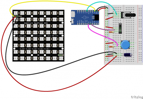
Having a hard time seeing the circuit? Click on the image for a closer look.
Below is the program I used for this project. It utilizes the Adafruit Neopixel Library.
//Desktop Light Sculpture by Melissa Felderman for SparkFun Electrnoics July/31/2018 #include <Adafruit_NeoPixel.h> //include afafruit library #define PIN 6 //LED matrix pin #define brightPot A0 //potentiometer to controll brightness #define pwrSwitch 4 //power switch #define momBut 5 //button to control LED mode int numPix = 64; //total LED count int brightPotVal; //Variable to hold pot value int pixelBrightness; //variabe to hold brightness value int switchState; //variable to hold switch value int butState; //variable to hold button value int mode = 0; //starting mode for switch state int prevButState = LOW; boolean butBool = false; int topMode = 4; //max number of LED modes in switch state unsigned long lastDebounceTime = 0; unsigned long debounceDelay = 200; Adafruit_NeoPixel strip = Adafruit_NeoPixel(numPix, PIN, NEO_GRB + NEO_KHZ800); //declare neopixel matrix //create an array for each row of LEDs int rowOne[] = {0, 1, 2, 3, 4, 5, 6, 7}; int rowTwo[] = {8, 9, 10, 11, 12, 13, 14, 15}; int rowThree[] = {16, 17, 18, 19, 20, 21, 22, 23}; int rowFour[] = {24, 25, 26, 27, 28, 29, 30, 31}; int rowFive[] = {32, 33, 34, 35, 36, 37, 38, 39}; int rowSix[] = {40, 41, 42, 43, 44, 45, 46, 47}; int rowSeven[] = {48, 49, 50, 51, 52, 53, 54, 55}; int rowEight[] = {56, 57, 58, 59, 60, 61, 62, 63}; void setup() { Serial.begin(9600); strip.begin(); strip.show(); pinMode(momBut, INPUT); pinMode(pwrSwitch, INPUT); } void loop() { brightPotVal = analogRead(brightPot); pixelBrightness = map(brightPotVal, 0, 1023, 0, 200); switchState = digitalRead(pwrSwitch); butState = digitalRead(momBut); strip.setBrightness(pixelBrightness); strip.show(); //function to debounce button if ((millis() - lastDebounceTime) > debounceDelay) { if ((butState == HIGH) && (butBool == false)) { butBool = true; mode++; lastDebounceTime = millis(); } butBool = false; } if (mode > topMode) { mode = 0; } Serial.println(mode); //switch state function to cycle through modes on LEDs, you can add as many or as few as you would like if (switchState == HIGH) { switch ( mode ) { case 0: for (int i = 0; i < numPix; i++) { strip.setPixelColor(i, 255, 255, 255); } strip.show(); break; case 1: rainbow(); break; case 2: buleGreenGradient(); break; case 3: pinkGradient(); break; case 4: yellowGradient(); break; } } else if (switchState == LOW) { for (int i = 0; i < numPix; i++) { strip.setPixelColor(i, 0, 0, 0); } strip.show(); } } //functions for LED colors void everyOther() { for (int i = 0; i < 8; i++) { strip.setPixelColor(rowOne[i], 255, 255, 255); strip.setPixelColor(rowThree[i], 255, 255, 255); strip.setPixelColor(rowFive[i], 255, 255, 255); strip.setPixelColor(rowSeven[i], 255, 255, 255); strip.setPixelColor(rowTwo[i], 0, 0, 0); strip.setPixelColor(rowFour[i], 0, 0, 0); strip.setPixelColor(rowSix[i], 0, 0, 0); strip.setPixelColor(rowEight[i], 0, 0, 0); } strip.show(); } void pinkGradient() { for (int i = 0; i < 8; i++) { strip.setPixelColor(rowOne[i], 185, 0, 255); strip.setPixelColor(rowTwo[i], 195, 0, 230); strip.setPixelColor(rowThree[i], 205, 0, 200); strip.setPixelColor(rowFour[i], 215, 0, 160); strip.setPixelColor(rowFive[i], 225, 0, 120); strip.setPixelColor(rowSix[i], 235, 0, 80); strip.setPixelColor(rowSeven[i], 245, 0, 40); strip.setPixelColor(rowEight[i], 255, 0, 10); } strip.show(); } void buleGreenGradient() { for (int i = 0; i < 8; i++) { strip.setPixelColor(rowOne[i], 0, 75, 255); strip.setPixelColor(rowTwo[i], 0, 100, 225); strip.setPixelColor(rowThree[i], 0, 125, 200); strip.setPixelColor(rowFour[i], 00, 150, 175); strip.setPixelColor(rowFive[i], 0, 175, 150); strip.setPixelColor(rowSix[i], 0, 200, 125); strip.setPixelColor(rowSeven[i], 0, 225, 100); strip.setPixelColor(rowEight[i], 0, 255, 75); } strip.show(); } void yellowGradient() { for (int i = 0; i < 8; i++) { strip.setPixelColor(rowOne[i], 255, 255, 25); strip.setPixelColor(rowTwo[i], 255, 220, 25); strip.setPixelColor(rowThree[i], 255, 190, 25); strip.setPixelColor(rowFour[i], 255, 160, 25); strip.setPixelColor(rowFive[i], 255, 130, 25); strip.setPixelColor(rowSix[i], 255, 100, 25); strip.setPixelColor(rowSeven[i], 255, 70, 25); strip.setPixelColor(rowEight[i], 255, 40, 25); } strip.show(); } void rainbow() { for (int i = 0; i < 8; i++) { strip.setPixelColor(rowOne[i], 255, 0, 0); } for (int i = 0; i < 8; i++) { strip.setPixelColor(rowTwo[i], 255, 100, 0); } for (int i = 0; i < 8; i++) { strip.setPixelColor(rowThree[i], 255, 255, 0); } for (int i = 0; i < 8; i++) { strip.setPixelColor(rowFour[i], 0, 255, 0); } for (int i = 0; i < 8; i++) { strip.setPixelColor(rowFive[i], 0, 255, 200); } for (int i = 0; i < 8; i++) { strip.setPixelColor(rowSix[i], 0, 0, 255); } for (int i = 0; i < 8; i++) { strip.setPixelColor(rowSeven[i], 255, 0, 255); } for (int i = 0; i < 8; i++) { strip.setPixelColor(rowEight[i], 255, 0, 130); } strip.show(); }
I hope you enjoyed this project! It was a lot of fun to make and I’m excited to continue building out the program for more LED colors, as well as making different designs on the laser-etched acrylic.
If you love this project and want to give it a go but don’t have access to digital fabrication tools, try checking out your local library or maker space. If all else fails there are always online digital fabrication services from which you can order your 3D print and laser-etched acrylic. As always, please share your thoughts, ideas, and suggestions about this project in the comments below!
Shop For This Project Download the Design Files
comments | comment feed
0 notes
Text
Design And Construction An Automatic Voltage Stabilizer Using Microcontroller
Design And Construction An Automatic Voltage Stabilizer Using Microcontroller
This Research Work is on Design And Construction An Automatic Voltage Stabilizer Using Microcontroller
Format: Ms Word Document
Pages: 75
Price: N 5,000
Chapters: 1-5
Get the Complete Project
Title Page
Certification/Declaration
Approval Page
Dedication
Acknowledgement
Abstract
Table of content
Chapter 1
Introduction
1:1 Introduction
1:2 Background of the Study
1:3 Statements of Problems
1:4…
View On WordPress
#A.C#automatic#Based#circuit#diagram#diagram microcontroller#diagram relay#diagram smart#diagram voltage#kit#microcontroller#pdf pic16f676#PHYSICS PROJECT TOPICS/MATERIALS#pic16f877a 5kva#stabilizer#stabilizer automatic#Type#Using#voltage
0 notes
Text
PROJECT TOPIC- CONSTRUCTION OF A MICROCONTROLLER BASED GATE
PROJECT TOPIC- CONSTRUCTION OF A MICROCONTROLLER BASED GATE
PROJECT TOPIC- CONSTRUCTION OF A MICROCONTROLLER BASED GATE ABSTRACT
Microcontroller based automate controller is a project design of a system that is used in operating a gate automatically. The system opens the gate automatically when a human being or car is about to enter a compound or exit a compound. The system works by sensing the light rays from the head lamp of the vehicle. The light…
View On WordPress
#microcontroller based automatic gate control#microcontroller based automatic railway gate control circuit diagram#microcontroller based automatic railway gate control project report#microcontroller based automatic railway gate control system abstract#microcontroller based automatic railway gate control system circuit diagram#microcontroller based automatic railway gate control system pdf#microcontroller based automatic railway gate control system project#microcontroller based automatic railway gate control system report#microcontroller based dam gate control system
0 notes
Link
Build 15+ complete Arduino projects from scratch! A car controlled using an app, a cell phone, games and much much more!
What you’ll learn
Build a remote-controlled car you can drive with a smart phone app
Build your own cell phone that you can make/receive calls and send/receive text messages with
Build games using the Arduino incorporating light, sound and joystick controllers
Understand components like ultrasonic sensors, motor drivers, servos, transistors, bluetooth/wifi/gsm modules
Understand many common electronic components and how they work
Have the confidence to build complex electronics projects
Learn how to prototype electronics projects
Be a confident maker and prototyper
Requirements
Be curious about Arduino
Have the desire to build fun, cool and exciting projects as a way to learn Arduino
Prefer a hands-on approach to learning
No previous electronics or programming knowledge needed
All electronics and programming principles will be taught from scratch
Arduino Uno Microcontroller
Arduino Start Up Kit will be helpful (connecting wires, breadboard, resistors, push button switches etc.) A kit will get you through at least 80% of the course.
Description
This is a hands-on, projects-based approach to learning the Arduino platform catered to all levels of experience. In this course, you will build projects such as:
An Arduino car that can be remotely driven using a smart phone app
Your very own Arduino phone that you can make/receive phone calls with and send/receive text messages
Your own Universal Arduino Remote that can copy and playback IR signals from any electronic device
An Arduino Online Weather Station that connects to the internet to retrieve and display weather information based on your location
Arduino game projects using light, sound and joysticks
Much much more…
No previous programming or electronics knowledge is required for this course! All electronics concepts and programming for each project will be explained step-by-step in detail.
You will quickly learn and become proficient with Arduino in this bootcamp by building complete projects from scratch. Here is the approach that is taken for each project:
A detailed background of all the electronics principles and operation of the electrical components for each project will first be discussed
The wiring of components and layout of the project will then be covered in the circuit diagram
Detailed step-by-step videos will then show how you how to wire up and assemble the components for the project
The code will be uploaded to demo the project and how it works
A detailed line-by-line code review will then describe how the software and hardware components play together
You will get the complete picture and it is a much better way to learn Arduino by creating full working projects from scratch!
Along the way, you will learn about and become extremely proficient with the following components and understand exactly how they work as they will be incorporated in projects:
Breadboards
LEDs
Active and Passive Buzzers
Switches
Potentiometers
Transistors
Ultrasonic Sensors
Seven Segment LEDs (single and four digit)
Infrared Receivers
Joysticks
8×8 Matrix LEDs
Shift Registers
DC Motors
Servos
LCD Screens
Bluetooth Modules
Wifi and GSM Shields
And much much more…
The course is broken up into a Simple Projects section, an Intermediate Projects section and an Advanced Projects section allowing you to progress to or start from any level based on how comfortable you are with Arduino.
If you are new to Arduino, the first lessons will get you quickly up to speed on what the platform is and how to use it. You can then progress to simple projects which get you comfortable with basic electrical components.
For those already familiar with Arduino who want to take their skills to the next level, you can jump straight to the intermediate projects section. There, we will focus on making game-type projects using the Arduino and even an infrared repeater that can allow you to copy, store, and playback any IR signal, just like your own universal remote.
Next, for those that might be already comfortable with Arduino, there is an advanced projects section where we tackle projects like an online weather station, remote-controlled car that you can drive with a smart phone app, and a working phone that can make actual calls and send text messages and many more.
I have always believed that project-based learning is the best approach where you actually learn by doing and building something that actually works. This is the approach I am taking in this course. I will explain all the electronics principles involved with each project, show you how to wire up the circuits and give detailed line-by-line code reviews on how it all works.
Don’t just take my word for it, here are what past students are saying about this course!
This is really a nice course with some great projects and use of add- on devices beyond most simple Arduino courses. The instructor is very easy to understand and does a great job. The only thing I would prefer is more projects and less watching jumpers getting plugged. 🙂 Don’t hesitate on this purchase if buying on special. I hope he updates the content so I get more stuff to watch! ~ Johnnie Norsworthy
Top notch Arduino course! Way better than a few of the other highly rated Arduino courses I have taken on Udemy. The projects range from easy to challenging and the instructor explains everything involved in great detail. Don’t think twice about joining this course. I have not seen better projects in any other Arduino course! Cheers! ~ Cody Willis
Lee is doing a great job of an instructor. I have no electrical background at all and can follow the course pretty easy. Lee is also super fast on answer your questions ~ Dat Ngyen
Loved this course! Instructor is clear and to the point! Can’t wait to see if he adds more projects to the course. ~ Joan Brixby
Learned so much! Excellent course! The projects I did were really fun. I think i am going to get the instructor’s Raspberry Pi Bootcamp course too! ~ Renny Becher
If you already have an Arduino or by purchasing an Arduino Kit (about $35 US), you will get most of the components needed to complete at least 80% of the course. The more advanced projects will require some additional parts but they are all really affordable. A detailed parts list by project and for the course is provided once you join the course, with links to online suppliers that are kept up to date. You can buy all the parts at once or select which advanced projects you want to work on and obtain only the specific additional components you need based on your electronics collection.
Who this course is for:
No previous electronics or programming knowledge required
Someone who is interested in learning about the Arduino platform
Someone interested in building cool projects
Someone interested in learning about electronics
Electronics hobbyist
Students
Makers or Inventors
Created by Lee Assam Last updated 4/2020 English English [Auto-generated]
Size: 6.64 GB
Download Now
https://ift.tt/2ZBbksO.
The post Arduino Bootcamp : Learning Through Projects appeared first on Free Course Lab.
0 notes
Text
OBSTACLE AVOIDING ROBOT

INTRODUCTION :
An Obstacle Avoiding Robot is a type of autonomous mobile robot that avoids collision with unexpected obstacles. In this project, an Obstacle Avoiding Robot is designed. It is an Arduino based robot that uses Ultrasonic range finder sensors to avoid collisions.
MATERIALS REQUIRED:
· Arduino NANO or Uno (any version)
· HC-SR04 Ultrasonic Sensor.
· LM298N Motor Driver Module.
· 4 BO Motors.
· Battery.
· Wheels.
· Chassis.
· Jumper Wires.
· Servo motor
BRIEF DESCRIPTION ON THE PROJECT:
In the above figure, Arduino is the main processing unit of the robot. Out of the 14 available digital I/O pins, 7 pins are used in this project design.
The ultrasonic sensor has 4 pins: Vcc, Trig, Echo and Gnd. Vcc and Gnd are connected to the +5v and GND pins of the Arduino. Trig (Trigger) is connected to the 9th pin and Echo is connected to 8th pin of the Arduino UNO respectively.
A Servo Motor is used to rotate the Ultrasonic Sensor to scan for obstacles. It has three pins namely Control, VCC and GND. The Servo Control Pin is connected to pin 11 of Arduino while the VCC and GND are connected to +5V and GND.
L293D is a 16 pin IC. Pins 1 and 9 are the enable pins. These pins are connected to +5V. Pins 2 and 7 are control inputs from microcontroller for first motor. They are connected to pins 6 and 7 of Arduino respectively.
Similarly, pins 10 and 15 are control inputs from microcontroller for second motor. They are connected to pins 5 and 4 of Arduino. Pins 4, 5, 12 and 13 of L293D are ground pins and are connected to Gnd.
First motor (consider this as the motor for left wheel) is connected across the pins 3 and 6 of L293D. The second motor, which acts as the right wheel motor, is connected to 11 and 14 pins of L293D.
The 16th pin of L293D is Vcc1. This is connected to +5V. The 8th pins is Vcc2. This is the motor supply voltage. This can be connected anywhere between 4.7V and 36V. In this project, pin 8 if L293D is connected to +5V supply.
WORKING PRINCIPLE:
Before going to working of the project, it is important to understand how the ultrasonic sensor works. The basic principle behind the working of ultrasonic sensor is as follows:
Using an external trigger signal, the Trig pin on ultrasonic sensor is made logic high for at least 10µs. A sonic burst from the transmitter module is sent. This consists of 8 pulses of 40 KHz.
The signals return back after hitting a surface and the receiver detects this signal. The Echo pin is high from the time of sending the signal and receiving it. This time can be converted to distance using appropriate calculations.
The aim of this project is to implement an obstacle avoiding robot using ultrasonic sensor and Arduino. All the connections are made as per the circuit diagram. The working of the project is explained below.
When the robot is powered on, both the motors of the robot will run normally and the robot moves forward. During this time, the ultrasonic sensor continuously calculates the distance between the robot and the reflective surface.
This information is processed by the Arduino. If the distance between the robot and the obstacle is less than 15cm, the Robot stops and scans in left and right directions for new distance using Servo Motor and Ultrasonic Sensor. If the distance towards the left side is more than that of the right side, the robot will prepare for a left turn. But first, it backs up a little bit and then activates the Left Wheel Motor in reversed in direction.
Similarly, if the right distance is more than that of the left distance, the Robot prepares right rotation. This process continues forever and the robot keeps on moving without hitting any obstacle.
APPLICATION OF THIS CONCEPT:
· Obstacle avoiding robots can be used in almost all mobile robot navigation systems.
· They can be used for household work like automatic vacuum cleaning.
· They can also be used in dangerous environments, where human penetration could be fatal
0 notes