#mosfet testing with multimeter
Explore tagged Tumblr posts
Visit Tumblr Blog
Explore Tumblr blogs with no restrictions, modern design and the best experience.
Last Seen Tumblr Blogs


Fun Fact
Post activity is at the highest at 4:00 pm EDT; notes peak at 10:00 pm EDT.
Text
Mosfet Testing......
#working #mobile #repair #mobilephone #mobilerepair #mobiles #mosfet #mobilephonerepairspecialist #MOSFET #mobicationhub #mobicationhub9509959090 #testing #mobilerepairtools #iPhone #androidrepair
#mosfet testing#mosfet#how to test mosfet#mosfet transistor#mosfet testing with multimeter#how to check mosfet#how to check mosfet with multimeter#easy method of testing mosfet#how to test mosfet using multimeter#n channel mosfet#smd mosfet testing#how to test mosfet with multimeter#how to test a mosfet#test mosfet#n channel mosfet testing#mosfets#mosfet test#mosfet explained#easy way to test mosfet#p channel mosfet testing#mosfet tutorial
0 notes
Text
Bosch VP44 VP30 VP29 Fuel Pump Repair Transistors IRLR2905
Introduction
Bosch VP44, VP30, and VP29 are electronic diesel fuel pumps used in a variety of diesel engines, including those in cars, trucks, and agricultural equipment. These pumps play a crucial role in fuel injection, ensuring the precise delivery of fuel under high pressure. However, over time, these pumps can develop electrical failures, primarily due to faulty transistors inside the electronic control module (ECM). One common solution to repair these fuel pumps is to replace the defective transistors with IRLR2905.
This article explores the role of the Bosch VP44, VP30, and VP29 pumps, the symptoms of failure, and the repair process using the IRLR2905 transistor.

Understanding Bosch VP Fuel Pumps
The Bosch VP series of fuel pumps are electronically controlled rotary pumps that regulate fuel delivery with precision. These pumps are widely used in modern diesel engines due to their efficiency and reliability. They function as a hybrid between traditional mechanical pumps and fully electronic common rail systems.
Key Features of Bosch VP Pumps:
Electronically controlled fuel injection
High-pressure delivery for efficient combustion
Compact design suitable for various diesel engines
Integrated electronic control unit (ECU) for real-time adjustments
Common Failures in Bosch VP44, VP30, and VP29 Pumps
Despite their reliability, these pumps are prone to failure due to electrical component degradation, especially in the ECU. The most common failure points include:
Transistor Burnout – Over time, the MOSFET transistors inside the pump’s ECU can degrade due to heat and electrical stress.
Capacitor Failure – Aging capacitors can lead to voltage fluctuations, causing erratic pump behavior.
Solenoid Wear – The high-pressure solenoid can become weak, leading to poor fuel atomization.
Wiring Issues – Corroded or broken wires can cause intermittent electrical faults.
Symptoms of a Failing VP Pump
Engine Stalling: The engine suddenly shuts down while driving.
Difficulty Starting: The engine cranks but does not start easily.
Loss of Power: Reduced acceleration and overall poor performance.
Error Codes: Diagnostic trouble codes (DTCs) such as P1689, P0216, or P0251 indicate pump failure.
Rough Idling: The engine runs inconsistently at idle.
Role of IRLR2905 Transistors in Fuel Pump Repair
The IRLR2905 is an N-channel MOSFET transistor that is widely used to replace defective transistors in the Bosch VP series pumps. It offers:
High current handling capacity (55A maximum drain current)
Low on-resistance for efficient energy transfer
Robust thermal performance for durability in high-temperature environments
These features make IRLR2905 a perfect replacement for faulty MOSFETs inside the ECU of the VP44, VP30, and VP29 fuel pumps.
Step-by-Step Repair Process Using IRLR2905
Tools and Components Needed:
IRLR2905 MOSFET transistors (replacement parts)
Soldering iron and soldering wire
Multimeter for testing circuits
Heat-resistant tweezers
PCB cleaner and flux
Protective gloves and goggles
Screwdrivers and pliers
Disassembling the Fuel Pump ECU:
Disconnect the battery: Safety first—always disconnect the vehicle’s battery before working on electrical components.
Remove the fuel pump from the engine: Depending on the vehicle, this may require removing covers, hoses, and mounting brackets.
Locate the ECU on the pump: The ECU is usually housed in a sealed metal casing on the side of the pump.
Open the ECU housing: Use a heat gun or small blade to carefully remove the sealant.
Replacing the Faulty Transistors:
Identify the defective MOSFETs: Use a multimeter to check for continuity and resistance values in the existing transistors.
Desolder the faulty transistors: Carefully remove the defective transistors using a soldering iron.
Prepare the IRLR2905 replacement: Apply flux to the board and align the new transistors in place.
Solder the new transistors: Ensure solid and clean solder joints for reliable electrical connections.
Test the circuit: Before reassembling the ECU, verify that all soldered components are functioning correctly.
Reassembling and Reinstalling the Fuel Pump:
Seal the ECU housing: Use an appropriate heat-resistant sealant to protect the board from moisture.
Reinstall the fuel pump: Secure all mounting points and reconnect the hoses and electrical connectors.
Reconnect the battery: Ensure all electrical connections are correctly restored.
Test the vehicle: Start the engine and monitor performance, checking for error codes and smooth operation.
Preventive Maintenance Tips
Regularly check for error codes: Use an OBD2 scanner to monitor ECU performance.
Keep fuel filters clean: Dirty fuel can contribute to pump failures.
Monitor engine temperature: Overheating can accelerate electrical degradation.
Inspect wiring regularly: Ensure no loose or corroded connections exist.
Conclusion
The Bosch VP44, VP30, and VP29 fuel pumps are vital components of diesel engines, but their electronic control modules can fail due to transistor degradation. The IRLR2905 MOSFET provides a reliable replacement solution, restoring pump functionality and extending its lifespan. By following a systematic repair process, mechanics and DIY enthusiasts can save significant costs compared to purchasing a new fuel pump. Regular maintenance and timely repairs can ensure the longevity of these fuel pumps, keeping diesel engines running efficiently.
0 notes
Text
Troubleshooting Common Issues In SMPS Designs

Despite their benefits, switched-mode power supplies (SMPS), which efficiently convert electrical power switching between different energy levels, can have a number of design flaws. During design, development, and operation, SMPS may run into a number of issues like component failure, excessive noise, overheating, and instability. To ensure dependable and effective functioning, it is crucial to comprehend these issues and know how to resolve them. This blog includes a thorough analysis of typical difficulties with SMPS designs as well as practical solutions for their diagnosis and troubleshooting.
Common issues in SMPS designs
Common issues in SMPS designs can significantly affect performance and reliability.
Instability and oscillation: A fluctuating or oscillating output voltage and insufficient control are common indicators of instability and oscillation. These problems are usually caused by inadequate phase margin, an inadequate compensation network, or a poorly designed feedback loop. In order to debug, the feedback loop needs to be appropriately built with a phase margin, and the stability of the loop properly analyzed using simulation tools. The components of the compensation network need to be checked, and the values of the resistors and capacitors need to be altered as necessary. To find instability situations and make necessary design adjustments, the loads need to be tested.
Excessive noise and EMI: High levels of electromagnetic interference or audible noise from the SMPS might be signs of excessive noise and EMI. Poor PCB layout, insufficient filtering, or rapid switching transients are frequently the cause of this. The PCB layout needs to be optimized to reduce loop regions and stable ground planes need to be provided in order to solve these issues. By employing the right capacitors and inductors and by improving or adding input and output filters, filtering can be improved. To manage switching transients and lower noise, soft switching strategies and snubber circuits must be used.
Overheating: Thermal shutdowns and overheated components, including switching transistors and diodes, are frequent signs of overheating. This may be the consequence of inadequate thermal management, high power dissipation, or inadequate cooling. Cooling must be improved by installing fans, heatsinks, or better airflow to address overheating, and enough ventilation must be available. To minimize power dissipation, components with reduced on-resistance should be chosen. For optimal heat transmission from heated components to heatsinks or the chassis, thermal pads and conductive materials must be used.
Component failure: The SMPS may malfunction or behave erratically as a result of a component failure; frequently, observable damage to parts like capacitors, transistors, or inductors is present. Overvoltage or overcurrent situations, subpar or underestimated components, and high operating stress are common causes. Multimeters and oscilloscopes must be used to find electrical problems and components should be physically checked for damage as part of the troubleshooting process. To avoid stress and failure, outdated components with higher voltage and current ratings should be replaced, and heat, overcurrent, and overvoltage safety circuits should be installed.
Poor efficiency: High power loss and excessive heat generation might result from inefficient operation. Suboptimal design, excessive conduction losses, or ineffective switching are frequently the causes of this problem. Using high-efficiency MOSFETs and considering synchronous rectification can increase efficiency. By utilizing low-resistance components and making sure that PCB trace design is correct, gate drive circuits can be optimized to minimize switching losses and reduce conduction losses. To improve overall efficiency, the complete SMPS design should be reviewed and optimized, taking into account topology, component selection, and thermal management.
Diagnostic tools and techniques
The ability to detect and fix problems with SMPS designs efficiently depends on the use of diagnostic tools and procedures.
Oscilloscope: Because it enables engineers to detect ripple and noise levels on the output, measure voltage and current waveforms, analyse switching transients and noise, and diagnose SMPS issues, an oscilloscope is a critical diagnostic tool. An oscilloscope aids in identifying problems with signal integrity and stability by giving an image of electrical signals.
Spectrum Analyzer: For the purpose of locating electromagnetic interference (EMI) problems, a spectrum analyser is essential. It quantifies electromagnetic emissions, breaks down noise into its frequency components, and evaluates how well shielding and filtering work. This tool facilitates the identification of EMI sources and the assessment of the interference-mitigating effectiveness of the design.
Thermal Camera: Thermal management in SMPS designs may be evaluated with the use of a thermal camera. It assesses the efficacy of cooling methods, visualises temperature distribution, and finds hotspots. A thermal camera helps to avoid component overheating and optimise cooling techniques by detecting locations of excessive heat.
Multimeter: Finally, for simple electrical measurements, a multimeter is a useful instrument. It monitors voltages and currents, verifies component values like capacitance and resistance, and detects open or short circuits. Its functionality is crucial for confirming that parts are operating correctly and finding fundamental electrical problems with the SMPS design.
Effective diagnostic tools and a complete understanding of the underlying causes of typical difficulties in SMPS systems are required for proper troubleshooting. It is important to tackle issues related to instability, noise, overheating, component failure, and low efficiency to guarantee dependable and effective functioning. Significant improvements in SMPS performance and reliability may be achieved by using the right diagnostic tools and following best practices in design and testing. Improving SMPS designs requires constant learning and modification as technology develops. Coming to technological development, Miracle Electronics is a well-known SMPS transformer manufacturer in India, whose proficiency in creating dependable and technologically-advanced transformers guarantees best-in-class efficacy and longevity for a wide range of applications. Miracle Electronics provides solutions that satisfy the strict specifications of contemporary electronic systems, increasing efficiency and dependability in every design.
Resource: Read more
0 notes
Text
Electrics, v3!
I wasn’t too happy with the last electrical switchboard, and having just bought an inverter I took the opportunity to redo it all.
I’d used a trailer plug and socket on the previous board to connect that board to the camper circuits, but it was a tight fit under the seat and I’d thought about trying to move it behind one of the seat backs.
I’d also added an Arduino + LCD display to run the power monitoring and control, but that failed almost immediately when I accidentally shorted out a MOSFET switch, so I abandoned that until I could rework it.
In the end it was easier to just get rid of the board all together and install everything on the wall behind the set back.
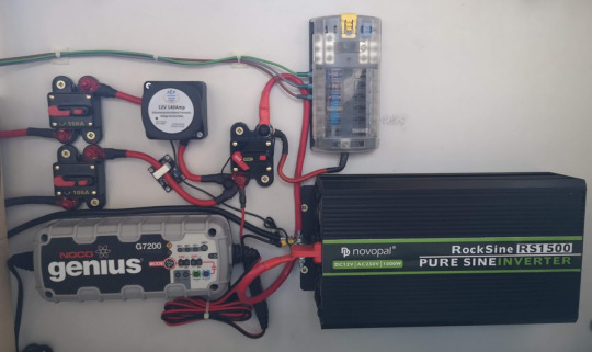
On the left side of the bench seat (not pictured) is where the wiring comes out of the cable channels. It’s still very messy, which is why I’m not showing photos. :D I will tidy it up, honest. There’s also a ground rail, which is attached to the vehicle chassis, to the leisure batteries, to various devices, and also via the thick black cable in the photo to the inverter.
On the right side (pictured) are the devices and fuses and all the switches that we need access to. The two large switches/breakers on the left are the lines in from the starter and leisure batteries. The starter battery is now wired in via a VSR, so it connects automatically now. Both batteries and the charger are connected together at the master power switch in the middle.
(If I ever get around to installing the solar panel and MPPT charger, that will go in here.)
The other side of that master switch goes to the fuse block and the inverter. The cabling out from that fuse block goes back to the left side, where a terminal block connects back to the van wiring.
I tested the inverter’s load while switched off - it consumes less than 5mA, so I’m okay with having it connected when the master power is on. However, if it’s switched on with no load, it consumes 1.4A, so that’s something to avoid. The inverter has a remote on/off switch and indicator, I’m not sure where to install that. But the mains power isn’t done yet anyway (space at top right of that panel!), so will cross that bridge later.
In getting rid of the previous panel, I’ve lost the other switches that were on that board. The charger switch isn’t an issue - if there’s power to the charger then it should charge! Having switches on some of the fuse-block outputs was nice (switch off the fridge, for example), but will live without those for now.
Apart from the one thick black negative cable to the inverter (and then also to the charger and the VSR), all the wiring here is all +12V. That helps keep it all neat. But I was concerned about having the high current +12V connectors exposed, so I bought some liquid electrical tape - that’s the red gunk you can see on the terminals of the breakers. I’ve put on 3 layers so far, but my multimeter still reads voltage through the insulation, so either it doesn’t work, or I’m going to have to keep applying more layers.

With a hole cut in the seat back, we have easy access to the master switch and the fuses, and also can get to the other switches and the charger too.

I’ll probably put a magnet at the top of that panel to hold it in.
Still to do: Arduino to monitor current and voltage levels. AC breaker box, with or without the option of inverter input.
1 note
·
View note
Photo

A digital multimeter is a test tool used to measure two or more electrical values—principally voltage (volts), current (amps) and resistance (ohms). It is a standard diagnostic tool for technicians in the electrical/electronic industries. Follow for more information posts 👇👇👇👇👇👇👇👇👇 Electronics Curiosities @electronics_curiosities @electronics_curiosities @electronics_curiosities @electronics_curiosities @electronics_curiosities Like Share Comment 👍 #digitalmultimeter #multimeters #voltage #current #transistor #capacitor #ammeter #amp #volts #mosfet #electronicengineer #engineering #electricalengineeringstudent #battery #resistor #dmm #potentiometer #power #watt #ac #dc #telecommunicationengineering #electrical #testing #diode #scr #zenerdiode #fet #bjt #varistor (at Electrical Engineering Works) https://www.instagram.com/p/CFCGEFbAdGG/?igshid=1efa0slw93xqc
#digitalmultimeter#multimeters#voltage#current#transistor#capacitor#ammeter#amp#volts#mosfet#electronicengineer#engineering#electricalengineeringstudent#battery#resistor#dmm#potentiometer#power#watt#ac#dc#telecommunicationengineering#electrical#testing#diode#scr#zenerdiode#fet#bjt#varistor
0 notes
Photo

Hi apes, I got today a new toy, and after charging a pair of cells I decide to have a look inside. @fogstar , no need to worry, I will not ask for warranty as of now . The device is well built, good case, the lcd light LED has a small bright spot on a corner but that is to be expected, maybe just my ocd. The springs on the contacts are quite snappy, be careful on fingers and battery wraps.
It is build around and MCU that has no part code on it, quite normal as people steal designs. Mirrored charging circuit, good soldering and good parts. The control mosfets are 30v and 4A, for a 0.5A/cell charger it is ok although I kinda wanted to see a bit of overkill here. The reverse polarity is done with Schottky diodes, by the part number ( i hate decrypting smd codes) they seems to be specialized diodes for reverse polarity protection.
I loved the fact that it barely gets warm ( somehow expected at 0.5A per cell charge) it points that the circuit is sized correctly. The charging current goes down as the cells are almost full, and the cut-off voltage seems to be around 4.19v. Once the cells are full it barely draws anything, I was to lazy to put a proper multimeter instead of the usb meter, the meter showed 0 but I would expect a few mA to run the circuit and power the display but it does indicate that it cuts the cells once full. When fully charging it draws between 0.8A to 1.1A with 2 cells. Did not try only 1 cell. The only thing I noticed, and maybe I don't understand how it works ( looping @XTAR in for info) is that the current indicator is stuck at max , 0.5A , even when the cells are almost full and the whole charger draws 0.2A, that meter is still at 0.5 amps. Maybe it will change when charging a small mA/h cell but not sure if it is a bug or I did not test the right setup.
Tested with some spare efest cells and my trusty samsung 2A charger. The usb meter, although a cheap thing it was tested on a calibrated multimeter and it is accurate.
0 notes
Text
Professional Training Institute (PTI) is a Training organization, which is well known for providing quality education in advance fields such as Embedded System, C, Linux, CAN, Basic electronics, digital electronics, presently these are the hottest and best job-providing sectors. As the world changing fast, the technologies also changing day by day, we at Professional Training Instituteupdate our syllabus after every six months, we train the students according to the present using technologies in the industries. We at Professional Training Institute train our student such a way that, it’s easy for them to work in industries as they will have good practical knowledge. We at Professional Training Institute provide practical training such a way that our student getting an edge over others. Our main motto is to focus on practical and hands-on training to the student so that they are able to face any kind of interview in the embedded domain.

The Syllabus is Followed by Embedded Training Institute in Bangalore
This is a 4-5 month course for B.E/B. Tech/MTech/ ME/ MCA/M. Sc Candidates Pre-final & Final Year with a background preferably Electronics, Electrical, Instrumentation or Computer science.
1. With this students will be handling their Mini & Final year project by themselves independently. If already completed engineering then this course will help to get the job. 2. Our embedded training institute in Bangalore will provide 100% job assistance to our students. We give our full effort to get a job/place. We are having a dedicated team how is working with the placements. 3. Course Code: PTIESD0a – Comprehensive Embedded Systems Design Course is divided into following Major headings.
a) Basic Electronics and Digital Electronics. b) Basic C. c) Tools including S/W and H/W. d) Basic of Hardware Concepts. e) Basic Embedded. f) Advance C. g) Advance Embedded. h) Basic Linux. i) RTOS concepts. j) Linux Internal and Linux Device Drivers.
Details Description of Syllabus of Embedded Systems Courses in Bangalore
Basics of Electronics and Digital Electronic
Basic Electronics
Resistors, Capacitors, Inductors.
PN-Junction.
Diodes.
Transistor.
MOSFET/CMOS.
Interpretation Data Sheet.
Half-Wave Rectifiers/ Full-Wave Rectifier.
Power Supply 3.3V,5.0V,12.0V, Voltage Regulators.
Crystals
Switches, Relays.
7-Segment
555 Timers in AS/MS/BS
Digital Electronics
Number System – Binary, Hex, Decimal,BCD System.
Addition/Subtraction of binary, 2’s complements.
Interconversion of number system.
Logic Gates – AND/OR/NOR/EXOR.
Filip-flop, Memory element.
Mux- De-Mux, Decoders.
Shift Registers.
Counters.
Basics C
CHAPTER 1: GETTING STARTED
What is C?
Data Types
Variables
Naming Conventions for C Variables
Printing and Initializing Variables
CHAPTER 2: SCOPE OF VARIABLES
Block Scope
Function Scope
File Scope
Program Scope
The auto Specifier
The static Specifier
The register Specifier
The extern Specifier
The register Specifier
The extern Specifier
CHAPTER 3: CONTROL FLOW CONSTRUCTS
if
if else
while
for
Endless Loops
do while
break and continue
switch
else if
CHAPTER 4: THE C PREPROCESSOR
#define
Macros
#include
Conditional Compilation
#ifdef
#ifndef
CHAPTER 5: MORE ON FUNCTIONS
Function Declarations
Function Prototypes
Returning a Value or Not
Arguments and Parameters
Organization of C Source Files
Extended Example
CHAPTER 6: BIT MANIPULATION
Defining the Problem Space
A Programming Example
Bit Wise Operators
Bit Manipulation Functions
Circular Shifts
CHAPTER 7: STRINGS & ARRAY
Fundamental Concepts
Aggregate Operations
String Functions
Array Dimensions
An Array as an Argument to a Function
String Arrays
Example Programs
CHAPTER 8: POINTERS (PART 1)
Fundamental Concepts
Pointer Operators and Operations
Changing an Argument with a Function
call
Pointer Arithmetic
String Functions with Pointers
Pointer Difference
Prototypes for String Parameters
Relationship Between an Array and a Pointer
The Pointer Notation *p++
CHAPTER 9: STRUCTURES
Fundamental Concepts
Describing a Structure
Creating Structures
Operations on Structures
Functions Returning Structures
Passing Structures to Functions
Pointers to Structures
Array of Structures
Functions Returning a Pointer to a Structure
Structure Padding
CHAPTER 9: STRUCTURES
typedef – New Name for an Existing Type
Bit Fields
unions
Non-Homogeneous Arrays
Enumerations
Tools Including S/W and H/W for Embedded Systems Training
KEIL
Making project in Keil.
Keil features/ tabs
Memory models in Keil.
Debugger setting in Keil.
Linker settings in Keil.
Multimeter
Measuring Voltage/Current/Registers
Measuring continuity
Introducing BBT – Baring Board Test.
CRO
Use of CRO.
What is Trigger?
How to do setting in CRO.
Measuring Voltage/current from CRO
Logic Analyzer
What is Logic Analyzer
How to use Logic Analyzer
What is the use of a logic analyzer
For which protocol we can use a logic analyzer.
Soldering Iron/Heat GUN/
How to use Soldering Iron.
Precaution needs to take.
Basic Hardware Concepts of Professional Training Institute
Designing Power supply
Design of power supply 5V.
Designing of 7 Segment Display Hardware
Study of 7 segment components
Designing Schematics of hardware implementation.
Hardware Design guidelines.
Important concepts during hardware Schematics design
Important concepts during hardware PCB lay-outing.
Active High/Active Low
Description of Active high and Active Low
EMI/EMC consideration
Use of Ground Plan
Use of De-coupling capacitor
Use of TVS Diode
Components Torrance and Data sheet study
Component Torrance study.
Consideration during designing.
Certification/Standard
CE/TUV/IC/ISI/IS/ISO
Basics of Embedded Systems
Microprocessor/Microcontroller
Basic Concepts and Review
Definition
Nomenclature
Buses – Address, Data, and Control
Architecture
Interfacing memory & I/O devices
Programming ( Assembly)
Monitor program
Micro-controller
Microcontroller Basic Concepts and Review
Architecture
Interfacing memory & I/O devices
Programming ( Assembly)
Assignments
Assembly Programming
Addition of two number.
Toggling Port with delay
Toggling Port with a timer.
Introduction of Interrupt.
Comparison interrupt and polling.
Communication with loopback.
Keyboard interface.
Controlling LED with Switches.
Embedded C
Embedded C & Integrated Development Environment
Embedded C Programming
Data types
Pointers
Arrays
Pointer functions
Loops
Introducing ARM Architecture
Induction of ARM Architecture
ARM7TDMI
Difference between ARM9/ARM11
Different ARM concepts
The advantage of ARM.
Advance C
Structure and union
Combination of Structure and union.
Bit fields in Structure.
Pointers to structure and union.
The advantage of Structure and union
Function Pointers
Microcontroller Basic Concepts and Review
Function pointers.
Callbacks
Advantage/use of functions pointers.
Dynamic memory allocation
Malloc
Calloc
free
re-alloc
File operations
Opening A file
Closing a file
Writing some data in a file and reading back and printing.
The different mode in which file can be open and write.
String operation
Srtcpy
strcmp
strcat
strlen
strstr
Pre-requisites for the Embedded Training in Bangalore:
1. B.E/B. Tech/MTech/ ME/ MCA/M.Sc Candidates Pre-final & Final Year with a background preferably Electronics, Electrical, Instrumentation or Computer science.
Professional Training Institute – Embedded Systems Training Institute in Bangalore
Our training method is different, our students get hands-on experience, they do experiments individually, which helps them to understand each part clearly like for example in embedded part we train them on UART protocol, we make them think and write a program for UART protocol, and we let them do communication between two devices using the UART protocol, by all these they will have good understanding of the UART protocol and they can easily use UART anytime in future. In this way, they get more interest to know about different technologies and we make them work and think.
We start our embedded system training from basic electronics, we teach the importance of electronics components, circuit design and we train them to design a power supply for different voltages. During c-programming classes we make our student think of the logic of each programmer, we never help them for write program, instead we help them to think and solve, this help them develop their logical skills and they can able to write any different programs.
We make student to discuss in class, and to give a seminar, which helps our students to develop the communication skills.
Learn More
More Tags: embedded training in Bangalore | embedded Linux training in Bangalore | best-embedded training institute in Bangalore | embedded training institute in Bangalore | list of embedded systems institute in Bangalore | embedded systems courses in Bangalore | embedded courses in Bangalore
#Embedded Training in Bangalore#embedded training institutes in bangalore#embedded systems courses in bangalore
0 notes
Text
AkitikA GT-102 review
buyers guide for iphone An e-mail from an old audiophile pal: “Herb, my buddy owns a recording studio, and he told me one of his $10k reference amplifiers stopped working and the manufacturer said it would take months to be repaired. So he went online and bought this 60W AkitikA solid-state amplifier to use while his big amp was being repaired. The trouble is, the kit cost only $314. (The studio guy bought his assembled and tested for $488.) Now, he likes the AkitikA more than his broke-down reference amp.” My friend wondered if I wanted to review the AkitikA amp (the name is a palindrome, based on a kit). “Hell yes!” I told him. “Kits are my roots!”
When I was in high school, my best friend was a radar technician for the Navy. He taught me Ohm’s law, and how to solder, dress wires, and use a multimeter. He practically forced me to build a Dynaco1 Dynakit Stereo 70 tube amplifier, as well as the matching PAS-2 preamplifier and FM-3 stereo tuner. I didn’t want to take tubes to college, so I also built Dynaco’s solid-state PAT-4 preamplifier and Stereo 120 amplifier, which I used to drive Dynaco’s A25 loudspeakers.
Oh, how I loved them. To this day, Dylan and the Doors have never sounded better! After moving to New York City, I built a solid-state Hafler DH-101 preamp and two (!!) DH-200 amplifiers, which I used to drive stacked pairs of Large Advent loudspeakers. Yahweh, Bob Marley, and The Specials loved this potent lively-up system as much as I did. Next, I started reading Audio Amateur and Speaker Builder magazines, buying used test instruments, and modifying my Dynaco and Hafler gear. By the late 1980s I’d advanced to building simple tube amplifiers from scratch, using parts cannibalized from antique radios. (I worshiped at the Philco 16B Tombstone.) Solder fumes, wire strippers, and building amps remain very appealing to me. For me, kits were the start of a new life one that led me to secret societies and darker corners of the audio underground. When I asked John Atkinson if I could review AkitikA’s GT-102 power amplifier, he said okay, but suggested that, because he would be testing it on his lab bench, I should request the factory-assembled, pre-tested version ($488). Which I did.
Description
Because the GT-102 is available as a kit I begin my description of it by quoting AkitikA’s “Satisfaction Guarantee” for this US-made amp:
Buy the kit.
Build the kit.
Listen to and enjoy the kit.
If within 30 days of receiving the kit you aren’t satisfied, return the kit. So long as your kit is correctly assembled, we’ll refund the price you paid, you just pay return shipping.
The GT-102 is a class-AB, 60Wpc stereo power amplifier in a case made of relatively thin steel. Its front panel sports only a logo and an illuminated, bright green plastic rocker switch for power on/off. On the rear panel are only an IEC power-cord inlet, two gold-plated RCA jacks, and two pairs of generic speaker binding posts. The GT-102’s interior is spartan, but studying its layout gives the potential kit builder a good idea of how much screwing and soldering will be required to build it.
The first thing to note is the steel wall separating the audio circuitry from the toroidal mains transformer and regulated power supply. Note the three deep-finned heatsinks: one behind the rear panel, for the power-supply regulator, and two in a row along the inside of the left side panel, one per channel, to cool the two LM3886 power operational amplifiers.
Now, before you get your knickers in a knot about an “audiophile-grade” power amplifier based on a lowly opamp instead of this year’s fashionable MOSFET, JFET,SIT, or bipolar device—you must understand that the AkitikA’s LM3886 op-amp is notorious and fashionable. The roots of the storied LM3886 can be traced back to 47 Laboratory’s 4706 Gaincard integrated amplifier, designed by Junji Kimura, which I reviewed for Listener magazine; Robert Deutsch reviewed it for Stereophile in December 2001.2 The Gaincard, introduced in 1999, had only nine parts per channel, short signal paths, minimal power-supply capacitance, and, with only one of 47 Lab’s Power Humpty power supplies, cost $3300 (a second Power Humpty cost an additional $1800).
The 4706 Gaincard’s high price, radical simplicity, and unorthodox power supply spawned concern among measurements- oriented audiophiles, but word quickly spread about how musically satisfying it could sound. After reviewing it, I bought the Gaincard and used it every day for 10 years with a pair of Rogers LS3/5a speakers. I’ve subsequently compared my Gaincard to one of its clones and one DIY version, and learned that all LM3886 op-amps are not created equal.
In using power op-amps, implementation is key. PCB layout, wiring routes, grounding strategies, heatsinking, power transformers, and especially power-supply design, will affect stability, transparency of sound, and the ability to drive speakers. My listening for this article, and what I see inside this amp, suggest that AkitikA’s owner and designer, Dan Joffe, has done a smart job with this LM3886 implementation. Kit builders should know that each of the GT-102’s three circuit boards is fitted with a lot of little parts, most of them resistors whose coded stripes identify their values. To build a GT-102, each tiny bit will need to be found, positively identified, properly positioned, and soldered to its board. (I recommend soldering no parts until each PCB board is stuffed full, in mechanically sound fashion.) That done, the rest of the assembly consists of bolting and screwing the boards, binding posts, power switch, ground lug, and power transformer to the GT-102’s chassis. I suggest working slowly and patiently while breathing fresh air (it’s best to solder in a place with good ventilation), and triple-checking each step. The minimum tools required for assembly are: a 30W, pencil-type soldering iron; a small sponge; fine (0.032"), 60/40 rosin-core solder; wire cutters and strippers; #1 and #2 Phillips screwdrivers; needle-nose pliers; a set of basic nut drivers; an inexpensive digital multimeter, to cross-check resistor values against your reading of their color codes; good lighting; and a magnifying glass.
AkitikA’s website says that assembly should take about eight hours, and that 97% of all first-time kit builders complete the GT-102 without a hitch. The remaining 3% get it right in the end, with a little easy guidance from AkitikA. I studied the assembly manual and found it exceptionally clear and idiot-proof.3 It looks just like a Dynaco or Hafler manual.
Listening
I cooked the AkitikA GT-102 on my workbench for three weeks, while writing the Follow-Up on Joseph Audio’s Pulsar loudspeaker elsewhere in this issue. The system I used with the Pulsars comprised Mytek HiFi’s Manhattan II DAC, and Pass Laboratories’ HPA-1 preamplifier and XA25 power amp. I thought this was the most balanced and spatially descriptive system I’d assembled since I began writing for Stereophile in 2014. Jeff Joseph, of Joseph Audio, heard it and approved. So did John Atkinson. Stereophile’s videographer Jana Dagdagan and I made a binaural video of its sound so you can experience it, too.4 I played this setup every day and never once questioned its verity, charm, or competence. It sounded so detailed and lively that I had zero motivation to swap out the XA25 for the GT-102.
you may also like: buyers guide for iphone
0 notes
Text
How To Check Mosfet ....
#mosfet #institute #jaipur #topinstitutes #mobicationhub #repairing #repairtools #PracticalClass #mobilerepair #mobilerepairing #mobilephonerepair #mobicationhub9509959090 #topinstitutesofmobilerepair #howtocheckmosfet
#how to check mosfet#how to check mosfet with multimeter#mosfet#how to test mosfet#mosfet testing#mosfet transistor#how to check mosfet with digital multimeter#n channel mosfet#how to test mosfet using multimeter#how to test mosfet with multimeter#check mosfet#mosfet checking#n-channel mosfet#how to check if a mosfet is bad#how to test a mosfet#test mosfet#mosfet multimeter check#mosfet testing with multimeter#mosfets#easy way to test mosfet
0 notes