#mosfet tutorial
Explore tagged Tumblr posts
Visit Tumblr Blog
Explore Tumblr blogs with no restrictions, modern design and the best experience.
Last Seen Tumblr Blogs


Fun Fact
Tumblr Inc. has $15.1M in annual revenue.
Text
Mosfet Testing......
#working #mobile #repair #mobilephone #mobilerepair #mobiles #mosfet #mobilephonerepairspecialist #MOSFET #mobicationhub #mobicationhub9509959090 #testing #mobilerepairtools #iPhone #androidrepair
#mosfet testing#mosfet#how to test mosfet#mosfet transistor#mosfet testing with multimeter#how to check mosfet#how to check mosfet with multimeter#easy method of testing mosfet#how to test mosfet using multimeter#n channel mosfet#smd mosfet testing#how to test mosfet with multimeter#how to test a mosfet#test mosfet#n channel mosfet testing#mosfets#mosfet test#mosfet explained#easy way to test mosfet#p channel mosfet testing#mosfet tutorial
0 notes
Text
0 notes
Text
Controlling Appliances

hydroMazing outside the box
Use Arduino to directly control appliances
Safety Concerns and Highest level of reliability
The Arduino Uno, and variants, should only be used for directly powering peripheral modules and not devices. Consider the maximum current consumption when determining what is a device and what is a module. A string of lights is more of a device as opposed to a panel indicator…
View On WordPress
#controller#DIY#electronics#hardware#how-to#interactive#Internet#making#modules#MOSFET#open-source#relays#safety#tech#tutorial#wireless
0 notes
Text
Mosfet as a switch

We saw previously, that the N-channel, Enhancement-mode MOSFET (e-MOSFET) operates using a positive input voltage and has an extremely high input resistance (almost infinite) making it possible to interface with nearly any logic gate or driver capable of producing a positive output.
We also saw that due to this very high input (Gate) resistance we can safely parallel together many different MOSFET until we achieve the current handling capacity that we required.
While connecting together various MOSFETS in parallel may enable us to switch high currents or high voltage loads, doing so becomes expensive and impractical in both components and circuit board space. To overcome this problem Power Field Effect Transistors or Power FET’s where developed.V
We now know that there are two main differences between field effect transistors, depletion-mode only for JFET’s and both enhancement-mode and depletion-mode for MOSFETs. In this tutorial we will look at using the Enhancement-mode MOSFET as a Switch as these transistors require a positive gate voltage to turn “ON” and a zero voltage to turn “OFF” making them easily understood as switches and also easy to interface with logic gates.
The operation of the enhancement-mode MOSFET, or e-MOSFET, can best be described using its I-V characteristics curves shown below. When the input voltage, ( VIN ) to the gate of the transistor is zero, Read more..
5 notes
·
View notes
Text
Moisture sensor -V2
The V1 version of the moisture sensor has now been trialed and is delivering good data. The remaining challenges are to reduce power consumption as much as possible and make a better board and container.
Running the sensor every 5 minutes shows that if the refresh rate is reduced to, say, 4 times a day, battery life should be good for a couple of months. However this test has only included the current draw when awake and sending; it minimises the quiessant current draw which will be much more significant over months.
SIM cards
I’ve tried several now and concluded that it is the setup cost per card which is the main cost. Both the COOP and GiffGaff have non-recurring PAYG accounts which cost about 10p/Mb . Each HTTP Post takes about 2k so at low data rates, this cost is insignificant. Both have a minimum top-up of £10 providing 5-10 GB of data, so these are fine for the occassional project. Thingsmobile is half that price to set up, can run multiple SIMs off the same account and would be best for a batch of devices.
Batteries
I bought some 18650 Li-ion batteries - 2 * 4200mAh for £10 - much cheaper than the LiPo battery £10 / 1500mAh. I’m not sure Im getting them fully charged with a cheap charger and need better.
Aerial
The aerial connector is rather fagile and needs care in connecting and discnnecting - there is some advice here https://learn.sparkfun.com/tutorials/three-quick-tips-about-using-ufl
The improved aerial does give a stronger signal .
LoRAWAN
This would be preferable to GSM and there were plans for a network in Bristol. There area few stations shown on this site
https://www.thethingsnetwork.org/community/bristol/
but sadly the project seems defunct.
Multiple Temperature sensors
It would be interesting to see how air temperature, which affects the respiratior rate from the tree ) compares with the ground temperature and another temperature sensor woul add little cost or power consumption ( 4mA when running) to the project. The One-wire protocol supports multiple serial sensors with a single pull-up resistor.
GPIO power
The main design change from V1 is to use a GPIO pin to supply the current for the sensors. I’d assumed that in deep-sleep the 3V3 pin would be off but in fact it’s on all the time, and although the sensors don’t draw much, its better to turn them on only when needed. They need a few hundred ms to stablize before reading. The moisture sensor draws 5 mA but being capacitive, it will draw more on startup (thanks Michelle Ben for alerting me to this issue). The Temperature sensors draw no more the 4mA but this adds up to 13mA for two. Tests show that the moisture sensor and one temp sensor run OK off one GPIO but it makes more sense to use the GPIO to trigger a MOSFET switch to power all three sensors and this wil be version 3.
Wiring and enclosure
My big problem is with the wiring. I decided to use 3 pin JST connectors for the sensors so they could be swapped. I will add another sensor for air temperature. I bought a kit to make up my own plugs but the tiny terminals defeated me and I bought some ready wired. Batteries can be exchanged in the battery pack.
The problem is how to wire it all up. Whilst it runs when wired with jumpers:

the veroboard shows just how hopeless my soldering is : no detectable bridges but it doesnt work and its tricky to wire to the right pins - I need a headset!


Later
I got the v2 board working at last thanks partly to encouragement from my Bristol Hackspace collegues. I made a parallel lashup with a breadboard - the TTGO chip is too big to fit a breadboard so I used the breadboard for the additional wiring with jumpers from the required pins and its easy to wire into the JST plugs; made sure that worked; cleaned up all the solder, checked for bridges and then slowly added each wire, testing as I went for bridges and that it worked with a second TTGO board. Still so easy to get bridges. And I have a head magnifier on order.

1 note
·
View note
Text
Class A Amps Explained & Compared: Valvet A4 Mk.II vs. Pass Labs XA30.5

After years of hearing about the benefits of Class A amplifiers, I finally got a taste in my system when the Valvet A4 Mk.II monoblocks arrived. Despite its cost and inefficiency, Class A operation has long been held as a gold standard of amplification by many in the high-end, Krell and Nelson Pass among its better-known evangelists. Different Class A amps have their distinct sonic character like any other amps, and no, Class A isn’t a guarantee of great sound. But one commonality I’ve heard from many of these big hot amps is a lovely naturalness and liquidity that came closer to tubes in capturing music’s tonal colors... as if all that bias current helped burn away the ills of solid state. Once I heard good Class A, many otherwise excellent Class AB amps seemed a bit bland and mechanical by comparison. This was borne out when the Valvet arrived while the excellent Bryston 4B Cubed was also in-house. While the powerhouse Bryston was a great amp in its own right, the Valvet just seems to have less electronic artifact and more musical blood flowing through its veins, to paraphrase an old colleague. I was hooked and craving more Class A, so I jumped at the opportunity to give the Pass Labs XA30.5 a try. Replaced by the XA30.8 a few years back, it’s an older design that became a bit of an icon as one of the more attainable ways (MSRP $5500) to achieve Class A nirvana. It makes for a fascinating design contrast with the Valvet - big American muscle vs. tidy German simplicity.
What is Class A again? 🤓
First, a quick refresher. “Class A” operation means the devices (in this case the output transistors of the amp, commonly MOSFET or bipolar [BJT] devices) have enough bias current applied to them to ensure they always stay conductive (“on”) throughout the entire voltage swing of the musical signal. Remember that transistors tend to behave like on-off switches that require a certain threshold current to become conductive. This non-linear behavior is called the transconductance curve, and the idea with Class A is you always have enough juice flowing to keep the device in the conductive, most linear part of the curve.

Non-linear transconductance (current vs. voltage) curve of a bipolar transistor (BJT). Amazing we can get good sound of of these things, eh? (Source: stackexchange.com)
In contrast, Class AB amplifiers utilize “push-pull” complementary (NPN/n-channel and PNP/p-channel) pairs of transistors taking turns handling the positive and negative swings of the musical signal. They will only apply enough current to keep both devices on for smaller signals, and as power increases one side of the push-pull will cease conducting while the other side takes care of business. This is a clearly a more efficient setup - no wasted power for a device that doesn’t need to be on - but one that does have one device always transitioning in or out of its ideal operating region. Even if it’s not doing the heavy lifting, it’s contributing non-linearity and this leads to distortion that typically requires some form of negative feedback to mitigate. (If you’d like to go a level deeper on the theory of all this, check out this tutorial.)
A couple observations that are obvious from a circuit perspective, but perhaps clouded by all the marketing speak in the audio biz. Firstly, virtually all single-ended audio amplifiers are Class A by definition, and all Class AB amplifiers are push-pull. There would be no point in designing a non-Class A single-ended amp for audio because it would distort massively whenever the signal exceeded its Class A bias range. Class A for push-pull means both devices are conducting all the time, but there is an interesting catch - if the output signal exceeds the amount of bias current to keep one side of the push-pull pair in its linear region, the amp still keeps working because the other device is conducting - it’s being pushed in the opposite direction on its transconductance curve, towards saturation (overload). This means unlike single-ended Class A, push-pull Class AB will simply start acting like Class B at high power levels. Secondly, not all Class A biasing is the same - yes, the device might be fully on, but how far into its operating region (where on the transconductance curve) has it been juiced? This is why e.g. when Pass Labs upgraded the XA30.5 to the XA30.8, they increased bias current significantly, resulting in an amp that was still rated at 30Wpc but used over 100 watts more at idle and weighed 25 lbs more.
Class A Power Ratings 🔌
With all that in mind, let’s look at the rated power of these two amps. The Pass Labs weighs 60 lbs/27 kg and is rated at 30 watts into 8 ohms, which is literally 1/10th the rated power of the similarly-sized Bryston 4B Cubed. The Valvet is rated at 55 watts into 8 ohms, with each compact monoblocks weighing 26 lbs/12 kg - it’s well under half the size and weight of the Pass. How can both be Class A, meaning they both operate at low efficiency, yet the Valvet is purportedly 83% more powerful in such a compact package? While I haven’t spoken with Valvet designer Knut Cornils about how he rated the power of the A4, Pass Labs is very clear that their 30Wpc rating is for fully Class A operation, but that the amp will continue delivering power with low distortion well past that. And indeed, when Stereophile measured the XA30.5 on the bench, it delivered 130 watts into 8 ohms and 195 watts into 4 ohms before hitting 1% distortion. Those famous Pass Labs bias meters (NOT power meters as on e.g. Macintosh amps) also tell you exactly when bias current starts to fluctuate, indicating the amp is leaving Class A. On my 92.5dB-efficient Audiovector SR 6 speakers, they would just start to wiggle on heavy bass notes or orchestral climaxes at high listening levels.

Valvet A4 power draw at idle. Double this for two monoblocks.
Since I wasn’t able to measure the actual bias current inside the amps, I took a look at idle power draw as a rough proxy. Though the Pass XA30.5 is rated at 238W at idle, I measured closer to 190W once fully warmed up; meanwhile, the Valvet monoblocks idled at around 90W each. So, pretty similar, which doesn’t mean their Class A biasing is the same (it depends on a host of other factors such as the voltage of the supply rails) but it hints to the Valvet not being “juiced” any more deeply into Class A despite its higher power rating. This is also borne out by the similar operating temperatures (toasty, but not burning hot) and the fact that the power supply in the Pass, while having less capacitance than the Valvet, likely has just as much (if not more) transformer muscle. I don’t know the rating of the Pass’s massive toroid but I suspect it’s more then double the 400VA in each Valvet.
With the caveat that this is conjecture based on the physical, electrical and sonic observations (more on those later), the Valvet’s 55 watts are likely closer to the 1% THD point where it has crossed over into Class AB, and not at full Class A. And as another point of comparison, I currently have the Gryphon Essence Class A power amp that’s rated at 50 watts Class A, and it weighs all of 100 lbs with an absolutely massive power supply. Just as all watts on amp ratings are not alike, neither are all Class A watts apparently.
Sonics 🎶
The Pass amp took some time to come out of its slumber after having been powered down for a while, but its famously warm, relaxed character was immediately discernible. After a couple days much of the initial “MOSFET mist” burned off and a wonderful synergy developed between Pass Labs amp, Audiovector SR 6 Avantgarde Arreté speakers and Furutech DSS-4.1 speaker cables. The XA30.5′s big tone, ripe bottom end and easy power nicely complemented the speed and range of the Audiovectors, requiring no softening or sugar coating from the exceedingly transparent Furutech wire. Compared to the Valvet, the Pass had a bigger sound with more generous bass that was borderline fat without ever getting sloppy. Interestingly the soundstage was noticeably wider as well, despite the Valvets being monoblocks which would ostensibly give them an advantage in channel separation. Vocals on the Pass were a little fleshier on a broader, more spaced stage, and dynamics felt a bit more grounded by that extra bass oomph.
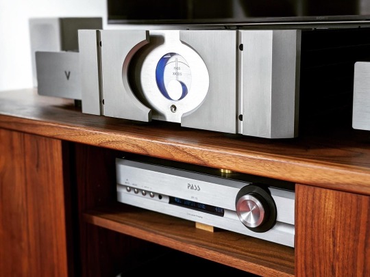
Pass’s XA.5-series styling certainly wasn’t known for its subtlety...
The Valvet counters with a faster, more incisive sound. One of the distinguishing features of the Valvet is the use of a single pair of transistors in the output stage. A number of manufacturers have been taking this approach as of late, including Pass in their XA25 amplifier which takes purism a step further by also eliminating the emitter degeneration resistors. The argument for such a simple topology is that no two transistors behave identically, and thus paralleling them causes some loss of fidelity as you can never get all of them at an identical ideal operating point and things kind of “average out.” The XA30.5 uses 10 pairs of MOSFETs per channel, and it’s only when you listen to the Valvet that you realize the Pass might have a few extra dancers in the troupe who aren’t quite as perfectly in lockstep with the music. The Valvet paints with a finer-tipped brush that can trace all the contours and curves of a musical line with great agility; the Pass doesn’t lack for resolution, but feels a tad slower and mushier, like a brush that has a bit of fuzz around it. This is particularly apparent in the upper frequencies where the Valvet has noticeably more sparkle and precision.
Tonally, both strike me as not deviating very far from neutral, but the Valvet has a subtle bit of upper midrange highlighting that methinks is in part due to its silver internal wiring. Silver tends to have a shinier sound to it, and when balanced well in a system it can really bring the details of a performance alive; but if not properly balanced, it risks sounding lean and forward. With the Valvet, the silver character is applied very judiciously, but I did find I needed to use more relaxed interconnects and speaker wires (e.g. Audience) to get the right overall tonality and perspective. The payoff is in the upper frequencies, where the Valvet makes the Pass sound a bit thick and cloudy by comparison. With a suitable source and preamp (the Gryphon Essence preamp was transformative in this respective), the tinkle of triangles and sheen of violins are presented with effortlessly clarity.

For reference, that’s a bookshelf speaker (Role Kayak) with 4″ woofers.
In terms of Class A qualities, both have wonderfully colorful midranges and a fair helping of liquidity and naturalness, but the Pass wears these quality more on its sleeve by sounding downright lush at times. It also maintains this warmth at higher volume levels where the Valvet can start to get a bit brighter and more strained, perhaps indicating where it’s leaving its Class A bias range. Where both excel is in conveying the lyricism of a tune or the palpability of an instrument or voice owing to their resolving, tonally complete midrange presentations. Both have a singing character that sounds and feels so organic and unencumbered vs. a typical Class AB amp. The Valvet does it with a slightly sharper focus on the lines around instruments and a bit more sparkle and dynamic alacrity; the Pass does it with a big, easy smoothness and weighty low end. Though the Valvet has no problem driving my full-range Audiovector speakers to satisfying volume levels, the Pass feels like it’ll be a bit more effortless and stable into a wider variety of speakers given its beefier output stage.
Going out on a limb: based on Gary Beard’s insightful remarks in Positive Feedback, methinks the Valvet might have more in common with the sound of the newer XA30.8. Gary’s observations of the XA30.5 align very closely with mine, and he describes the 30.8 as being more precise and incisive vs. the 30.5, similar to how I hear the Valvet vs. the 30.5. I would certainly expect the newer Pass to have more grunt than the Valvet given its even more massive power supply, but the Valet might capture some of the delicate qualities of the Pass XA25 as well. Both of those amps would make a really interesting comparison to the Valvet.
Closing Thoughts 🤔
Nit-picking power ratings aside, the Valvet A4 and Pass XA30.5 are both fantastically musical amplifiers that deliver plenty of the famed Class A magic with verve and character. It’s no coincidence that after the Valvet landed in my system, the next two amplifiers I’ve sought out - the Pass and the Gryphon Essence - are also Class A. This isn’t to say I’ll never go back to Class AB (and I’m actually expecting a Class D amplifier soon 😱), but after years of swearing I’d only seek out more practical amps that weren’t so ridiculously big and hot, the Class A bug has bitten me pretty hard. If tonal purity and musical nuance are top priorities for you, amps like the Valvet and Pass Labs deserve a spot on your audition list.
1 note
·
View note
Text
How a MOSFET Works - with animation! | Intermediate Electronics
How a MOSFET Works – with animation! | Intermediate Electronics
In this tutorial, using some animation, Josh explains how a MOSFET works. These Metal Oxide Semiconductor Field Effect Transistors are strangely straightforward in their operation but the logical leap to create them, and the way they have changed the way the world works is amazing. While there are different types of Field Effect Transistors (FETs), the MOSFET is a great example of how a field…
View On WordPress
0 notes
Video
tumblr
Zeus Mining Maintenance Tutorial: Replacing the 2N7002mos Tube Chip on the Antminer S19 Control Board The 2N7002 is a logic level MOSFET with low on-resistance. MOSFETs have a low gate-to-source threshold voltage of 2.1V, which typically makes MOSFETs even suitable for 3.3V application circuits. To replace: https://www.zeusbtc.com/ASIC-Miner-Repair/Parts-Tools-Details.asp?ID=1175
0 notes
Text
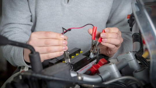
Can I charge the motorcycle battery with a charger?
The user can easily charge the battery of his motorbike by using a USB car charger. This will reduce the time and effort required in charging the battery.
In this tutorial, we will look at how to charge a 24V battery of a motorcycle with a USB car charger.
How to Charge a Battery of a Car with a Charger?
If you are using an external battery charger, the first thing you need to do is plug into the car’s power socket. It will then start charging your battery.
If you have a USB cable, you can connect it to the car’s USB port and use it to charge your phone. It should be noted that there are some cars that do not have any USB ports or can only be charged via an external power source.
These cars must also be plugged into the car’s power socket so if you want to charge them, make sure you have a compatible power source for them as well.
What is a MOSFET and why do we need it?
According to The Moto Gears, MOSFET is a type of field-effect transistor that consists of an insulator and a metal gate. The gate is separated from the source by a thin film of metal, which allows current to flow through the gate when it is in its high-voltage state. The insulator forms a barrier to prevent any current from passing through the gate, and thus prevents it from conducting.
A mops circuit consists of two parts: an input terminal and an output terminal. When the input terminal has its high voltage at zero volts, it will conduct current to the output terminal when it changes states to high voltage (when in its low-voltage state). When this happens, this part of the circuit becomes a MOSFET (an n-channel field-effect transistor).
Can I Charge Motorcycle Batteries With A Charger?
A charger is an item that you can use to charge your mobile phone. Many of us have a charger at home, but we don't use it. We may not know how to charge our mobile phone and we may not even know where the charger is at home.
This article is a review of the charger that i have been using for the last 3 years. I am sure you will find it useful.
We need to think about charging motorcycles with a charger. It is a common problem for many people and even for professionals. In this article, we will discuss the problem of charging motorcycles with a charger and how you can solve it.
How Can I Use a Charger to Charge My Motorcycle Battery?
This article will help you understand the concept of charging your motorcycle battery.
You can use a charger to charge your motorcycle battery. A charger is a device that is used to charge a battery, usually an electric car's or motorcycle's battery. It works by connecting the positive and negative terminals of the battery together and then allows them to flow freely through it. This process takes about 2 hours for an electric car's or motorcycle's batteries, and about 4 hours for an ordinary household appliance.

A charger does not need a separate power source, as it uses electricity from your home’s electrical system or from the grid if you have solar panels on your house or farm. It can also be used with batteries that are not connected to mains electricity in order to provide them with power .
Conclusion
In order to charge your motorcycle battery, you may need a USB car charger. This charger can be used to charge your motorcycle battery while you are on the road.
When you're on the road, you need to be able to charge your battery as soon as possible. Using a USB car charger is a good way of doing it.
1 note
·
View note
Text
Channel Mosfet

MOSFET Tizen deezer 2.
N Channel Mosfet Circuit
P Channel Mosfet Operation
N Channel Mosfet Symbol
ST's P-channel MOSFET portfolio is optimized to meet a broad range of requirements for load switch, linear regulator, automotive applications and specifically designed for portable applications. The MOSFET is another category of field-effect transistor.There are two types of MOSFET, Enhancement mode MOSFET and Depletion mode MOSFET. Major Brands BS250 N-Channel MOSFET Transistor, TO-92, 3 Pin, 5.2 mm H x 4.2 mm W x 4.8 mm L (Pack of 10) 5 $8 79 ($0.88/Transistor). This Article Shows A Detailed And Clear Explanation Of MOSFET Working, Structure, Analysis, Example, Applications, Benefits And Many Others. If you need to switch high current and or high voltage loads with a micro controller you'll need to use some type of transistor. I'm going to be covering how to use a MOSFET since it's a better.
The MOSFET is an important element in embedded system design which is used to control the loads as per the requirement. Many of electronic projects developed using MOSFET such as light intensity control, motor control and max generator applications. The MOSFET is a high voltage controlling device provides some key features for circuit designers in terms of their overall performance. This article provides information about different types of MOSFET applications.
MOSFET and Its Applications
The MOSFET (Metal Oxide Semiconductor Field Effect Transistor) transistor is a semiconductor device which is widely used for switching and amplifying electronic signals in the electronic devices.The MOSFET is a three terminal device such as source, gate, and drain. The MOSFET is very far the most common transistor and can be used in both analog and digital ckt.
The MOSFET works by varying the width of a channel along which charge carriers flow (holes and electrons). The charge carriers enter the channel from the source and exits through the drain. The channel width is controlled by the voltage on an electrode is called gate which is located between the source and drain. It is insulated from the channel near an extremely thin layer of metal oxide. There is a different type of MOSFET applications which is used as per the requirement.
Types of MOSFET Devices
The MOSFET is classified into two types such as;
Depletion mode MOSFET
Enhancement mode MOSFET
Depletion Mode: When there is zero voltage on the gate terminal, the channel shows its maximum conductance. As the voltage on the gate is negative or positive, then decreases the channel conductivity.
Depletion Mode MOSFET
Enhancement Mode
When there is no voltage on the gate terminal the device does not conduct. Twitch deezer. More voltage applied on the gate terminal, the device has good conductivity.
Enhance Mode MOSFET
MOSFET Working Principle
The working of MOSFET depends upon the metal oxide capacitor (MOS) that is the main part of the MOSFET. The oxide layer presents among the source and drain terminal. It can be set from p-type to n-type by applying positive or negative gate voltages respectively. When apply the positive gate voltage the holes present under the oxide layer with a repulsive force and holes are pushed downward through the substrate. The deflection region populated by the bound negative charges which are allied with the acceptor atoms.
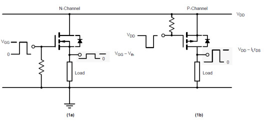
P- Channel MOSFET
The P-Channel MOSFET consist negative ions so it works with negative voltages. When we apply the negative voltage to gate, the electrons present under the oxide layer through pushed downward into the substrate with a repulsive force. The deflection region populates by the bound positive charges which are allied with the donor atoms. The negative voltage also attracts holes from p+ source and drain region into the channel region.

P-Channel MOSFET
N- Channel MOSFET
When we apply the positive gate voltage the holes present under the oxide layer pushed downward into the substrate with a repulsive force. The deflection region is populated by the bound negative charges which are allied with the acceptor atoms. The positive voltage also attracts electrons from the n+ source and drain regions into the channel. Now, if a voltage is applied among the drain and source the current flows freely between the source and drain and the gate voltage controls the electrons in the channel. In place of positive voltage if we apply a negative voltage (hole) channel will be formed under the oxide layer.
N-Channel MOSFET
MOSFET Applications
The applications of the MOSFET used in various electrical and electronic projects which are designed by using various electrical and electronic components. For better understanding of this concept, here we have explained some projects.
MOSFET Used as a Switch
In this circuit, using enhanced mode, a N-channel MOSFET is being used to switch the lamp for ON and OFF. The positive voltage is applied at the gate of the MOSFET and the lamp is ON (VGS =+v) or at the zero voltage level the device turns off (VGS=0). If the resistive load of the lamp was to be replaced by an inductive load and connected to the relay or diode to protect the load. In the above circuit, it is a very simple circuit for switching a resistive load such as LEDs or lamp. But when using MOSFET to switch either inductive load or capacitive load protection is required to contain the MOSFET applications. If we are not giving the protection, then the MOSFET will be damaged. For the MOSFET to operate as an analog switching device, that needs to be switched between its cutoff region where VGS =0 and saturation region where VGS =+v.
Auto Intensity Control of Street Lights using MOSFET
Now-a-days most of lights placed on the highways are done through High Intensity Discharge lamps (HID), whose energy consumption is high. Its intensity cannot be controlled according to the requirement, so there is a need to switch on to an alternative method of lighting system, i.e., to use LEDs. This system is built to overcome the present day drawbacks of HID lamps.
Auto Intensity Control of Street Lights using MOSFET
This project is designed to control the lights automatically on the highways using microprocessor by variants of the clock pulses. In this project, MOSFET plays major role that is used to switch the lamps as per the requirement. The proposed system using a Raspberry Pi board that is a new development board consist a processor to control it. Here we can replace the LEDs in place of HID lamps which are connected to the processor with the help of the MOSFET. The microcontroller release the respective duty cycles, then switch the MOSFET to illuminate the light with bright intensity
Marx Generator Based High Voltage Using MOSFETs
The main concept of this project is to develop a circuit that delivers the output approximately triple to that of the input voltage by Marx generator principle. It is designed to generate high-voltage pulses using a number of capacitors in parallel to charge during the on time, and then connected in series to develop a higher voltage during the off period. If the input voltage applied is around 12v volts DC, then the output voltage is around 36 volts DC.
This system utilizes a 555 timer in astable mode, which delivers the clock pulses to charge the parallel capacitors during on time and the capacitors are brought in a series during the off time through MOSFET switches; and thus, develops a voltage approximately triple to the input voltage but little less, instead of exact 36v due to the voltage drop in the circuit. The output voltage can be measured with the help of the multimeter.
EEPROM based Preset Speed Control of BLDC Motor
The speed control of the BLDC motor is very essential in industries as it is important for many applications such as drilling, spinning and elevator systems. This project is enhanced to control the speed of the BLDC motor by varying the duty cycle.
EEPROM based Preset Speed Control of BLDC Motor
The main intention of this project is to operate a BLDC motor at a particular speed with a predefined voltage . Therefore, the motor remains in an operational state or restarted to operate at the same speed as before by using stored data from an EEPROM.
Before using Praat to do sound analysis, we have to be clear about know that what information we can get from Praat. Table 1 presents some major acoustic variables we usually use to analyze the speech sounds. 49) for visual presentation of the variables. Praat is a free software package used for speech analysis in phonetics. It is designed and continuously developed by Paul Boersma and David Weenink of the University of Amsterdam. It is a flexible tool that offers a broad range of standard and non-standard procedures such as spectrographic analysis, speech synthesis, articulatory synthesis and neural networks. Praat allows you to divide up the sound signal into temporal stretches or intervals, and to assign text or labels to these intervals. It does this by means of what it calls a TextGrid. The basic idea is that one might want to divide a signal into intervals in more than one way. Praat scripts Phonetics Laboratory Scripts and batch processes are a handy way of saving time while performing repetitive operations. In this page we share some of the Praat scripts we use in our Lab. All the scripts include instructions (either at the begining of the file or in the first form of the script). PRAAT is a very flexible tool to do speech analysis. It offers a wide range of standard and non-standard procedures, including spectrographic analysis, articulatory synthesis, and neural networks. This tutorial specifically targets clinicians in the field of communication disorders who want to learn more about the use of PRAAT as part of an. Praat phonetics.
The speed control of the DC motor is achieved by varying the duty cycles (PWM Pulses) from the microcontroller as per the program. The microcontroller receives the percentage of duty cycles stored in the EEPROM from inbuilt switch commands and delivers the desired output to switch the driver IC in order to control the speed of the DC motor. If the power supply is interrupted, the EEPROM retains that information to operate the motor at the same speed as before while the power supply was available.
LDR Based Power Saver for Intensity Controlled Street Light
In the present system, mostly the lightning-up of highways is done through High Intensity Discharge lamps (HID), whose energy consumption is high and there is no specialized mechanism to turn on the Highway light in the evening and switch off in the morning. Recoverit download mac.
LDR Based Power Saver for Intensity Controlled Street Light
N Channel Mosfet Circuit

P Channel Mosfet Operation
Its intensity cannot be controlled according to the requirement, so there is a need to switch to an alternative method of lighting system, i.e., by using LEDs. This system is built to overcome the present day, drawback of HID lamps.
This system demonstrates the usage of LEDs (light emitting diodes) as light source and its variable intensity control, according to the requirement. LEDs consume less power and its life is more, as compared to conventional HID lamps.
The most important and interesting feature is its intensity that can be controlled according to requirement during non-peak hours, which is not feasible in HID lamps. A light sensing device LDR (Light Dependent Resistance) is used to sense the light. Its resistance reduces drastically according to the daylight, which forms as an input signal to the controller . A cluster of LEDs is used to form a street light. The microcontroller contains programmable instructions that controls the intensity of lights based on the PWM (Pulse width modulation) signals generated.
The intensity of light is kept high during the peak hours, and as the traffic on the roads tend to decrease in late nights; the intensity also decreases progressively till morning. Finally the lights get completely shut down at morning 6 am, to resume again at 6pm in the evening. The process thus repeats.
SVPWM (Space Vector Pulse Width Modulation)
The Space Vector PWM is a sophisticated technique for controlling AC motors by generating a fundamental sine wave that provides a pure voltage to the motor with lower total harmonic distortion. This method overcomes the old technique SPWM to control an AC motor that has high-harmonic distortion due to the asymmetrical nature of the PWM switching characteristics.
In this system, DC supply is produced from the single-phase AC after rectification, and then is fed to the 3-phase inverter with 6 numbers of MOSFETs. For each phase, a pair of MOSFETare used, and, therefore, three pairs of MOSFETs are switched at certain intervals of time for producing three-phase supply to control the speed of the motor. This circuit also gives light indication of any fault that occurs in the control circuit
N Channel Mosfet Symbol
Therefore, this is all about types of MOSFET applications, Finally, we will conclude that, the MOSFET requires high voltage whereas transistor requires low voltage and current. As compared to a BJT, the driving requirement for the MOSFET is much better.Furthermore, any queries regarding this article you can comment us by commenting in the comment section below.
0 notes
Text
MOSFET as a Switch

We now know that there are two main differences between field effect transistors, depletion-mode only for JFET’s and both enhancement-mode and depletion-mode for MOSFETs. In this tutorial we will look at using the Enhancement-mode MOSFET as a Switch as these transistors require a positive gate voltage to turn “ON” and a zero voltage to turn “OFF” making them easily understood as switches and also easy to interface with logic gates.
The operation of the enhancement-mode MOSFET, or e-MOSFET, can best be described using its I-V characteristics curves shown below. When the input voltage, ( VIN ) to the gate of the transistor is zero, the MOSFET conducts virtually no current and the output voltage ( VOUT ) is equal to the supply voltage VDD. So the MOSFET is “OFF” operating within its “cut-off” region. Read more..
0 notes
Text
Tutorial Arduino Boost Converter Simulasi Proteus 8
Tutorial Arduino Boost Converter Simulasi Proteus 8
Sebelumnya saya menulis tentang artikel buck converter konvensional dengan arduino dan kali ini saya lanjutkan menulis artikel yang berkaitan dengan boost converter atau rangkaian penaik tegangan dan arduino sebagai kontrol output teganganya. Beda dengan sebelumnya yang mana mosfet yang digunakan memerlukan frekuensi lumayan tinggi kisaran 50 Khz. dan yang untuk boost converter arduino ini tidak…

View On WordPress
0 notes
Text
How to Transfer Data From One USB Hard Drive to Another USB
youtube
How to Transfer Data From One USB Hard Drive to Another USB |USB to USB data transfer cable (Unboxing + Review) | Transfer Files From USB Flash To Any Smartphone Without PC, ****************************************************************** If You Want To Purchase the Full Project or Software Code Mail Us: [email protected] Title Name Along With You-Tube Video Link Project Changes also Made according to Student Requirements http://svsembedded.com/ è https://www.svskits.in/ M1: +91 9491535690 è M2: +91 7842358459 ****************************************************************** 1. PEN DRIVE TO PEN DRIVE DATA TRANSFER USING RASPBERRY PI, 2. USB TO USB Data Transfer using Raspberry Pi, 3. Pendrive to pendrive data transfer without pc, 4. How to Transfer Data From One USB Hard Drive to Another, 5. How to Replace the Redmi Note 3/Redmi Note 3 Pro Screen, 6. USB TO USB Data Transfer using Raspberry Pi, 7. Micro USB Hub - Simultaneous Charging & OTG - works only on some Windows/Android devices, 8. DIY Very Easy and Simple to Make diy USB Speaker | Powerful Ultra Amplifier Circuit, 9. Portable Raspberry Pi 3 Project - Raspberry Pi Portable Computer, 10. Pen Drive Life Hack - How to Turn Usb Pendrive into OTG Pendrive, 11. USB to USB data transfer cable (Unboxing + Review), 12. Easy Transfer 3 in 1 OTG USB Flash Drive for Android, iPhone & Computer, 13. Water Cooled Raspberry Pi 3, 14. How to Replace the Xiaomi Mi Max Screen, 15. Creating rawprogram.xml and patch for flashing LG Qualacomm mobiles, 16. Transfer Files From USB Flash To Any Smartphone Without PC, 17. Arduino based women safety security system using gsm and gps modem, 18. Raspberry Pi Mount a USB Drive, 19. Mobile to Pen Drive Data Transfer in 5 Seconds, 20. Simple Basic audio Amplifier Circuit using 1 MOSFET Transistor, 21. How to Copy Data from Laptop to Pen drive, Computer to Pen Drive to Laptop, Computer, 22. Smart Garbage Collecting Truck Using Arduino, GSM, GPS and Internet of Things (IOT), 23. How to Assemble or Build a Computer - easy way, 24. program arduino with android smartphone, 25. Android Phone to Pen Drive Directly Transfer Images, Video, Music & All Date, 26. How to transfer files to Pendrive using OTG cable in Moto G4 Plus December 2020, 27. RJ45 Crimping Tutorial - Straight Cable Crimping - Network Cable Color Code, 28. HOW TO SEND FILES COMPUTER TO PENDRIVE, 29. How to Copy or Transfer Data from a USB Flash Drive to a Computer, 30. How to use a pen drive with android to transfer DSLR pics without a computer, 31. WiFi Home Door Lock| Blynk | iot project, 32. Don't buy a GSM module, use your old phone, 33. Computer Basics: Hardware, 34. Basic concept of Arduino in Hindi | Arduino tutorials for beginners part, 35. Control Your Room Lights With Your Mobile | Make Your Home "Smart" | Arduino Uno FULL Setup, 36. Raspberry Pi Reading Car Diagnostics – Data, 37. Hand Gesture Controlled Robot using Arduino | How to Make a Gesture Control Robot, 38. Top 10 IoT(Internet Of Things) Projects Of All Time | 2020, 39. What is Arduino? Arduino Projects? Arduino Vs Raspberry Pi3, 40. DHCP Explained - Dynamic Host Configuration Protocol, 41. Network Troubleshooting using PING, TRACERT, IPCONFIG, NSLOOKUP COMMANDS, 42. How to Format a Drive using Command Prompt, 43. How to configure a Shared Network Printer in Windows, 44. Four Distributed Systems Architectural Patterns by Tim Berglund, 45. LET`S BUILD - my first Raspberry Pi SMART MIRROR, 46. Arduino RFID Sensor (MFRC522) Tutorial, 47. Android Studio For Beginners Part
1 note
·
View note
Text
Como consertar fontes atx de computadores Curso Conserto Fonte ATX de Computadores e faturar

Acesse agora o curso

https://hotm.art/fonteatx
fonte, fonte atx, atx, fonte de computador, eletrônica, conserto, computador, fonte de pc, como, dicas, defeito, fontes atx, queimada, teste, curso, consertando, reparo fonte atx, capacitor, diodo, corrente, aprenda, consertar, pc, liga, eletrônica geral, faça você mesmo, diy, como consertar, passo a passo, curso fonte atx, fonte queimada, eletrônica básica, manutenção em fontes atx, testando, multimetro, não, para, canal amor a vida, amor a vida, alcyj, descobrir, como consertar fonte atx, transistor, curso de fonte, curso conserto em fonte atx, conserto fonte real, curso fonte, fonte com defeito, manutenção, fontes para computador, curto, duplo, primário, conserto de fonte, mosfet, curso fontes atx, solda, abrindo, técnico, tutorial, alta, tensão, aula, componente, desliga, gira, circuito, como consertar fontes atx, conserto fonte, como testar fonte atx, resistor, completo, como consertar fonte, não liga, hm-2090, placa, curso de fonte atx, em, de, tensão power good, consertar fonte, banggood, 10, 2090, 3040, 3045, aprenda a conserta fonte atx, computadores, suporte, ti, informática, 220v, 110v, manutenção de desktop, desktop, soldagem, wellington ti, fonte não liga, p4, 24 pinos, consertando fonte queimada, troca de capacitor queimado, aprenda eletronica, noções de eletrônica, como soldar placas eletronicas, solda eletrônica, montar fonte, power supply diagram, projeto de fonte, fonte de alta potencia, electrolabcanaleletronica2016, fonte atx de bancada caseira, como fazer uma fonte atx de bancada, fonte de bancada, fonte de 12v, como fazer uma fonte de bancada, como consertar uma fonte de pc, como funciona uma fonte atx, secundário, fonte chaveada, smps, acoplador óptico, aula de fontes, conserto fonte de computador, conserto fontes atx, andrecisp, curso manutencao de fontes, reaproveitando, pirógrafo, hikari, hm, ferro, sugador, 30a, pasta, termica, calor, dissipador, montando, 12volts, 3.3volts, 5volts, -5volts, -12volts, grátis, explosões, capacitores, retificador, retificação, onda, completa, meia, ntc, amortecer, para que serve, aula 1, erros cometidos, erros, simular, simulação, peça, funcionamento, entrada, energia, elétrica, alternada, proteções, dobrador, dobradores de tensâo, com, curso conserto em fontes de computador, curso conserto de fontes atx, curso conserto de fontes de computadores, conserto de fontes, como consertar uma fonte atx, manutenção de fontes atx, preventiva, teste de transistor, defeito na fonte, tipo de defeito, tensão de stand by, como consertar fonte de pc, como consertar fonte de computador, pesquisa de defeito, como achar o defeito, stand, by, fria, trincada, alimentação, voltagem, 350v, 5v, 12v, 3.3v, 175v, descarregar, identificando, encontrando, acoplador, óptico, variação, canal, amor, vida, alcy, josé, silva, montagem de computadores, pc gamer, como montar um pc do zero, aprenda a montar um pc, monte seu pc do zero, intel, amd, gigabyte, msi, windows, microsoft, testando fonte atx, ligar fonte atx, como testar uma fonte, video aula fonte atx, conserto fontes, curso conserto de fontes, fonte do computador não liga, como consertar uma fonte, queimado, torrada, computador não liga, passo, surpresa, ligar, ohm, fusivel, ikari, hm2090, abrir, volts, ampere, amperes, potencia, potência, real, nominal, fontímetro, fontimetro, descobrindo, ventoinha, vibra, curso de fonte de pc, curso de fonte de computador, conserto de fonte atx, consertando fonte atx, consertando fonte de pc, consertando fonte, aprenda consertar fonte, video aula, descobrir o defeito, ganhe dinheiro, venda de curso, vendendo curso, afiliado, defeito fonte atx, conserto fonte atx, reparando fonte atx, transistores chaveadores, circuito chaveador com defeito, eu conserto minha fonte, como consertar uma fonte atx – transistor chaveador em curto, capacitor estufado, chaveador, arrumar fonte, placa mãe, placa de vídeo, reparo, concertar, reparo em fonte at� de computador como concertar, como conserta/8fmtfqzk, qual melhor fonte atx?, conector atx 24 pinos, como testar uma fonte atx?, secundário da fonte atx, circuito de saída, exemplos práticos de consertos, simulações de defeitor, termômetro infra-vermelho, sugador de solda, simulações de erros, aula 10, gratis, exemplo prático, aula prática, experiências, erres cometidos, passa a passo, liga e para, testadores de fonte atx, consertar fonte atx, manutenção fonte atx, curso manutenção de fonte atx, como reparar fonte atx, pwm, ci, ci pwm, encontrar, como encontrar, como descobrir, defeito no pwm, kit solda, ferramenta, testando ci, detalhes, dica, metodo, facil, pratico, eficiente, integrado, basico, desarma, desarmando, defeito no ci, curso aula manutencao fonte atx bt eletronica adendo analise sc6105, manutencao fonte, defeito fonte, diagrama esquematico da fonte, circuito
The post Como consertar fontes atx de computadores Curso Conserto Fonte ATX de Computadores e faturar appeared first on Cursos Online.
from WordPress http://www.buytravelhotel.com/como-consertar-fontes-atx-de-computadores-curso-conserto-fonte-atx-de-computadores-e-faturar-2/?utm_source=rss&utm_medium=rss&utm_campaign=como-consertar-fontes-atx-de-computadores-curso-conserto-fonte-atx-de-computadores-e-faturar-2
0 notes
Text
Project : gathering info
Before further continuing my project, I had to first do some research onto the topic and how all of the components are used as well as how my particular project would work. My lecturer pointed me in the direction of a YouTube channel with some tutorials on building drones from Arduino boards. https://www.youtube.com/channel/UCjiVhIvGmRZixSzupD0sS9Q . This channel had a set of videos for both brushless and brushed drones with links to a website for code and templates. One problem I found consistently with this channel was a lack of explanation behind the instructions. As only a single combination of board and radio were shown and his example/useable code only accounted for this. This was a problem as I used a different board and chip structure. The tutorials were also reused in some parts leading to a hard time watching them in order or finding specific information.
Link to code and website :
https://www.electronoobs.com/eng_arduino_tut23_parts1.php
https://www.electronoobs.com/eng_arduino_tut23_sch1.php
http://www.electronoobs.com/eng_robotica_tut5_1.php
And YouTube playlists :
https://www.youtube.com/playlist?list=PLsR1AO4QH1AztoVVaw4sKqnq0RcA3rO7v
https://www.youtube.com/playlist?list=PLsR1AO4QH1Azezx2KBeHrlakiOjN65BGX
after looking at the tutorials i bought a list of parts:
-5 IRFZ44N Transistor Mosfet’s
-4 SR5100 Schottky Diodes
-2 NRF24L01 wireless Transceivers
1 GY-521 MPU-6050 3 axis accelerometer
4 3.7v 1000mAh rechargable batteries
1 - resistor kit including 10Kohm resistors
1 Arduino Leonardo micro-controller
the design for the circuit diagram is here (some parts where changed later to fit changes in information available to me).

0 notes
Photo

Laptop Chip Level Repair – Mosfets 2 Today i am going to show you how to test mosfet on laptop motherboard. its very easy to learn. more in formation and more tutorials available please visit this ... source
0 notes