#networklayer
Explore tagged Tumblr posts
Visit Tumblr Blog
Explore Tumblr blogs with no restrictions, modern design and the best experience.
Last Seen Tumblr Blogs


Fun Fact
Tumblr’s reach among the 26-to-35-year-olds in the US is 11%.
Text
Static and Default Routing Configuration on GNS3 | Step-by-Step Guide - 2025
youtube
#ping#internetworkingdevices#Switch#ICMP#datalinklayer#framing#mac#macaddress#hub#bridge#collision#Applicationlayer#networklayer#icmp#ccna#ccnacourse#ccnaclasses#ccnatraining#ccna200301#ccnaonline#routing#switches#switching#router#routingprotocols#vlan#trunking#dtp#stp#Spanningtree
0 notes
Video
youtube
Understanding Cyber-Security In-Depth Network Layer Internet Protocol [C...
0 notes
Text
Networking - OSI Model

The OSI ( Open System Interconnection ) model is actually a pretty overlooked topic in general. The model which is responsible for the reason why you are able to view this website and even use the internet. The model which was created mainly to standardize computing systems to be able to communicate with each other. Without the OSI model, each company would probably have their own ways of communication which would make it so that computing system bought from a company will not work for the other. The Open Systems Interconnection model (OSI model) is a conceptual model that characterises and standardises the communication functions of a telecommunication or computing system without regard to its underlying internal structure and technology. Its goal is the interoperability of diverse communication systems with standard communication protocols.Wikipedia The model itself is basically a universal standard for computing networks. There are a total of 7 layers in the OSI model, each layer having its own job and importance. If you ever tried any DDoS services, you should be familiar with the layers. For example, application-layer attacks target the 7th layer and the protocol layer attacks target the 3rd and 4th layers which are also known as the internet and transport model. Offnfopt, Public domain, via Wikimedia Commons Physical Layer The Physical Layer is the lowest layer of the whole model and consists of physical tools/devices - LAN Cable, Optical Fiber Cable. This layer tr Read the full article
0 notes
Text
Technical Question: Transport-Layer and Network-Layer
Technical Question: Transport-Layer and Network-Layer
[ad_1]
Hi could someone tell me what protocols IOTA is using?
Transport-Layer: application side, means no need for a specific protocol?
Network-Layer: will probably still be IPv6?
Sorry but i dont really know where to ask such questions other here
[ad_2] View Reddit by DifferentRatio0 – View Source
View On WordPress
0 notes
Text
OPC UA server on a FPGA using open62541
Overview
Open Platform Communications Unified Architecture (OPC-UA - IEC62541) is a standardized platform-independent architecture which provides a service-based data exchange. In combination with TSN it allows new possibilities when it comes to high interoperability and deterministic communication.
Based on the open62541 implementation the following steps show how everything has to be setup to get it up and running on a FPGA (Artix7 with MicroBlaze). In combination with NetTimeLogic’s complete FPGA based TSN solution you get the full solution for industrial communication 4.0.
The example FPGA project and the application are available here:
https://github.com/NetTimeLogic/opcua
The open62541 implementation is available here:
https://github.com/open62541/open62541
Introduction
It is not straight forward to get the open62541 OPC UA stack up and running on an embedded system even if FreeRTOS and lwip is supported. The following implementation description is based on the open62541 documentation which describes how to build the library and how to implement a basic OPC UA server. The application creates an OPC UA server thread which is running under FreeRTOS with lwip.
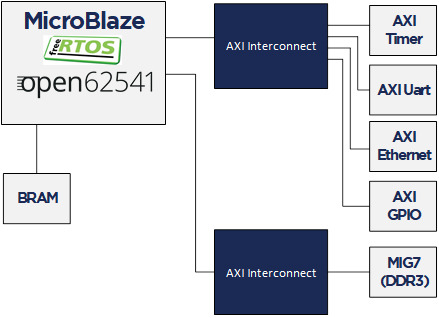
The FPGA use a MicroBlaze softcore with DDR3, Axi Ethernet Lite, Axi Uart Lite AXI GPIO and AXI Timer. As hardware an Arty A7-100T development board from DIGILENT is used.
Required tools
To build the full project, the following tools are required:
Xilinx Vivado 2019.1
Xilinx SDK 2019.1
CMAKE (Python 2.7.x or 3.x)
UA Expert
BSP adjustments for LWIP
Open62541 supports “freertosLWIP” as an architecture. In that case it uses the libraries of the target device which are the ones of the BSP in Xilinx SDK.
To be able to compile the open62541 library some adjustments for the lwipopts.h file are needed:
Line 10-19 https://github.com/open62541/open62541/blob/master/arch/common/ua_lwip.h
Since this file is managed by the BSP in Xilinx SDK, manual modifications are overwritten when the BSP is generated. With the following workaround, it is possible to add the additional defines over the BSP setting GUI.
1. Go to: C:\Xilinx\SDK\2019.1\data\embeddedsw\ThirdParty\sw_services\lwip211_v1_0\data
2. Open the lwip211.tcl
3. Search the proc generate_lwip_opts {libhandle} and go to the end of this procedure
4. Add before the line puts $lwipopts_fd "\#endif" the following code:
#OPEN62541 implementation
set open62541_impl [expr [common::get_property CONFIG.open62541_impl $libhandle] == true]
if {$open62541_impl} {
puts $lwipopts_fd "\#define LWIP_COMPAT_SOCKETS 0"
puts $lwipopts_fd "\#define LWIP_SOCKET 1"
puts $lwipopts_fd "\#define LWIP_DNS 1"
puts $lwipopts_fd "\#define SO_REUSE 1"
puts $lwipopts_fd "\#define LWIP_TIMEVAL_PRIVATE 0"
puts $lwipopts_fd ""
}
5. Save the file
6. Open the file lwip211.mld
7.Add the new Parameter e.g. at line 47:
PARAM name = open62541_impl, desc = "Used as an open62541 implementation?", type = bool, default = false;}
8.Save the file
9. Restart Xilinx SDK
After this change and a restart of Xilinx SDK the new option will be visible in the BSP settings GUI of the lwip.
Design preparation
Before everything is ready to build the open62541 library, the implemented FPGA design from Xilinx Vivado and a software application project in Xilinx SDK is needed. In this example project a MicroBlaze design with DDR3 is used (unfortunately the application does not fit into the available block RAM).
Vivado
The Vivado project can be created with the available tcl script. By running the implementation of the Vivado project the bitstream can be created. With File->Export->Export Hardware the hardware definition can be created.
File->Launch SDK starts the SDK.
Xilin SDK
In Xilinx SDK a new empty Application Project with the OS Platform “freertos10_xilinx” can be created.
File->New->Application Project.
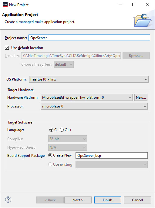
After the project is created some adjustments in the OpcServer_bsp are needed
Select lwip211 as supported libraries
Go to the lwip211 and adjust following parameter:
api_mode = socket_API
open62541_impl = true
Go to the freertos20_xilinx and adjust the following parameters:
Check_for_stack_overflow = 1
total_heap_size = 2097152
Re-generate BSP sources
The environment is now ready to start with CMake.
CMake
The easiest way is to work with the CMake GUI. Later it can be used in Xilinx SDK.
CMake for open62541 is used with following adjustment:
UA_ENABLE_AMALGAMATION = ON
UA_ENABLE_HARDENING = OFF
UA_ARCH_EXTRA_INCLUDES = <path to microblaze/include>
UA_ARCH_REMOVE_FLAGS = -Wpedantic -Wno-static-in-inline -Wredundant-decls
CMAKE_C_FLAGS = -Wno-error=format= -mlittle-endian -DconfigUSE_PORT_OPTIMISED_TASK_SELECTION=0 -DconfigAPPLICATION_ALLOCATED_HEAP=3 -DUA_ARCHITECTURE_FREERTOSLWIP
UA_LOGLEVEL = 100 (optional for debugging)
1. Start the CMake GUI
2. Select the correct source code path where the open62541 GIT repository is located and define the path where you want to build the binaries:

3. Click Configure:
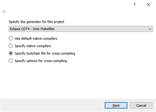
4. Select the CMake file which defines the compilation toolchain and other settings:

5. Click again on Configure and after that on Generate
6. The Unix Makefiles are now ready and can be added Xilinx SDK workspace:
File->Open Projects from File system
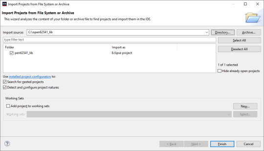
7. Now it should be possible to generate the open62541.c/h file in Xilinx SDK.
Make Target->all
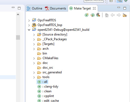
8. The workspace should have now following structure:

Creating the OPC UA server application
C/C++ Build settings
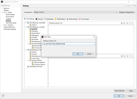
For a compilation without errors some adjustments in the application project Build settings are required.
1. Add the symbol for UA_ARCHITECTURE_FREERTOSLWIP
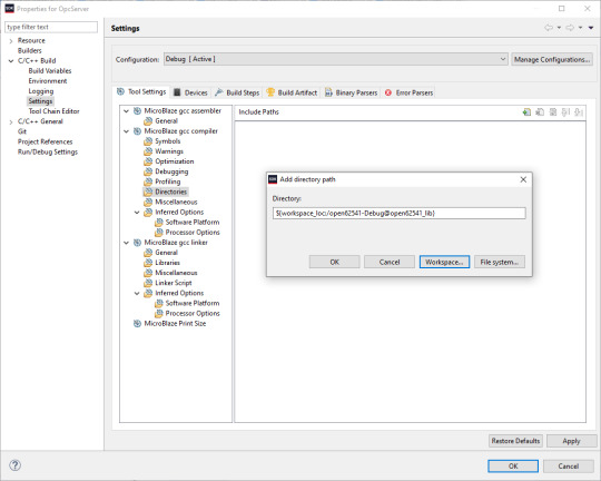
2. Add the open62541 build directory as include path
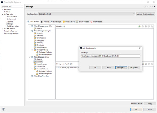
3. Add the open62541 build directory as library search path
4. Link the folder to the source location of open62541.c/h

5. Add an exclusion pattern that only the open62541.c/h are used:

Linker script
The linker script for our OPC UA server application needs some small adjustments.
With Xilinx->Generate linker script a new lscript.ld with following settings can be created:
Heap Size: (min) 1MB
Stack Size: (min) 1MB

Now the application project should be ready for a successful compilation.
OPC UA Server app
The complate Workspace is here available:
https://github.com/NetTimeLogic/opcua/tree/master/Src/Sdk_workspace
In Xilinx SDK the source file OpcServer.c can be imported to the OpcServer application project.
The thread stack size is defined with 4096 it might be possible that the application is not running properly with other values. However, the hook functions for MallocFailed or StackOverflow might be helpful.
In a first step the network initialization is done. This includes auto negotiation, ip configuration, interface binding and starting the lwip receive thread. After that the opcua thread gets started.
Important for a working server is the configuration and especially the buffer size of the network layer. With the following settings, the server was running without any problems:
config->networkLayers->localConnectionConfig.recvBufferSize = 32768; config->networkLayers->localConnectionConfig.sendBufferSize = 32768; config->networkLayers->localConnectionConfig.maxMessageSize = 32768;
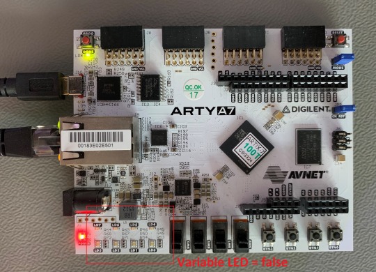
Before the server is started an object and a variable are added to the server. Additionally, a callback for the variable is configured, which allows to control the LEDs on the ArtyA7 board by an OPC client. After that the server gets started and runs until the running variable is set to false (never in this case).
Connecting to the OPC UA Server
After a successful implementation of the MicroBlaze FPGA design, building the open62541 library and compiling the OPC UA server application everything is ready.
The Arty A7 board should be connected to the PC over USB and the RJ45 is connected to a network interface adapter.
1. Open a serial terminal for the debug print out (baud rate: 115200)
2. Loading the bitstream (from Vivado or SDK)
3. Run the Application (from SDK)
4. If the application has successfully started, in the serial terminal following text is printed out:
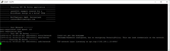
5. Start UaExpert
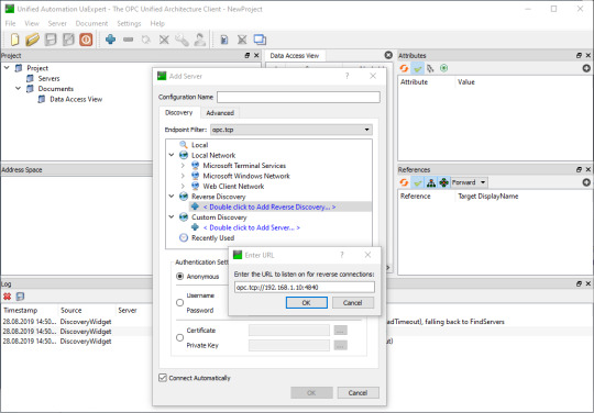
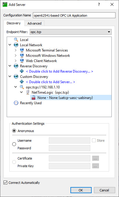
6. Add the server via “Custom Discovery” with the configured open62541 hostname
7. Expand the added server to add the connection. In the serial terminal you get already some information that a new connection over TCP was detected
8. After a successful connection in UaExpert the defined object a variable are visible.
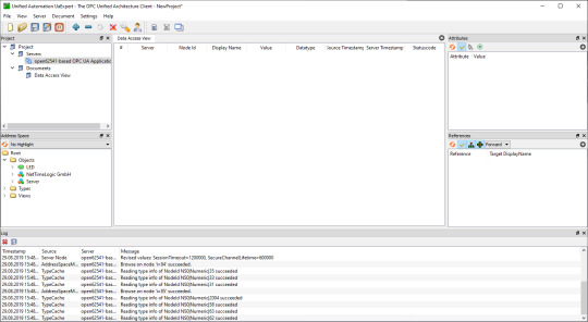
9. The variable LED can now be added to the Data Access View via drag & drop
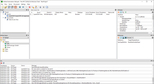
10. By changing the boolean value of the variable, the LEDs on the ArtyA7 can be switched on /off.

Summary
To get an open62541 server running on a MicroBlaze softcore following adjustments are needed:
Add the defines in the lwip BSP for lwipopts.h:
#define LWIP_COMPAT_SOCKETS 0
#define LWIP_SOCKET 1
#define LWIP_DNS 1
#define SO_REUSE 1
#define LWIP_TIMEVAL_PRIVATE 0
Adjust the BSP settings for lwip:
api_mode = socket_API
open62541_impl = true
Adjust the BSP settings for FreeRTOS:
Check_for_stack_overflow = 1
total_heap_size = 2097152
Adjust CMake options for open62541:
UA_ENABLE_AMALGAMATION = ON
UA_ENABLE_HARDENING = OFF
UA_ARCH_EXTRA_INCLUDES = <path to microblaze/include>
UA_ARCH_REMOVE_FLAGS = -Wpedantic -Wno-static-in-inline
-Wredundant-decls
CMAKE_C_FLAGS = -Wno-error=format= -mlittle-endian
-DconfigUSE_PORT_OPTIMISED_TASK_SELECTION=0
-DconfigAPPLICATION_ALLOCATED_HEAP=3
-DUA_ARCHITECTURE_FREERTOSLWIP
UA_LOGLEVEL = 100 (optional for debugging)
Generate a linker script with at least: 1MB heap and 1MB stack
Adjust the C/C++ build settings / include sources/libraries
Define the thread stack size to 4096
Adjust the buffer size of the server config:
config->networkLayers->localConnectionConfig.recvBufferSize = 32768;
config->networkLayers->localConnectionConfig.sendBufferSize = 32768;
config->networkLayers->localConnectionConfig.maxMessageSize = 32768;
1 note
·
View note
Text
#civillian #must #demystify #intel @law .@law @laws @harvard_law .@berlin @ap @reuters @bbc_whys @france24 @snowden @haaretzcom @judge .@judges @fisa .@deutschland the realdeal is simply a networked decentralised controlsystem ruling exploiting the civilpopulation with intelmethods depends on realms of control each intheir own way nobigdeal as any slea zy northkorea behind the courtains more intel networked integrated decentralised swift i nfo within own bunch and networklayer but semi autistic towardsother networks withcommon broad info for each but else decentralised each exploits rules their populations as they want all in a hierarchy foodchain with verfassungsschutz on topofit ///// how the german govt and its controlsystem kept the case daytime and themother allalong where i suspec ted new warcoma s itislikely they mutate to be immune and that since 90s ifnot earlier u sually itis federalgovt over stategovt landesverfassungsschutz proxies 5dictators timecon trollers accomplice shuffled interest groups like firms invitedfind intel radiocontroller o f fake zombi namewho played whosayhomersimpsoy is masseldorn landesverfassungsschutz sss exxxbadensen towhale usuallytheyknowwho radio controls and setsup names and hooker smeariti s criminal controlsystem german govt landesverfassungsschutz for their usually govt inter estof somany crimes how they rulelandesverfassungsschutzand controller of molest harms night
#civillian #must #demystify #intel @law .@law @laws @harvard_law .@berlin @ap @reuters @bbc_whys @france24 @snowden @haaretzcom @judge .@judges @fisa .@deutschland the realdeal is simply a networked decentralised controlsystem ruling exploiting the civilpopulation with intelmethods depends on realms of control each intheir own way nobigdeal as any slea zy northkorea behind the courtains more intel networked integrated decentralised swift i nfo within own bunch and networklayer but semi autistic towardsother networks withcommon broad info for each but else decentralised each exploits rules their populations as they want all in a hierarchy foodchain with verfassungsschutz on topofit ///// how the german govt and its controlsystem kept the case daytime and themother allalong where i suspec ted new warcoma s itislikely they mutate to be immune and that since 90s ifnot earlier u sually itis federalgovt over stategovt landesverfassungsschutz proxies 5dictators timecon trollers accomplice shuffled interest groups like firms invitedfind intel radiocontroller o f fake zombi namewho played whosayhomersimpsoy is masseldorn landesverfassungsschutz sss exxxbadensen towhale usuallytheyknowwho radio controls and setsup names and hooker smeariti s criminal controlsystem german govt landesverfassungsschutz for their usually govt inter estof somany crimes how they rulelandesverfassungsschutzand controller of molest harms night
#civillian #must #demystify #intel @law .@law @laws @harvard_law .@berlin @ap @reuters @bbc_whys @france24 @snowden @haaretzcom @judge .@judges @fisa .@deutschland the realdeal is simply a networked decentralised controlsystem ruling exploiting the civilpopulation with intelmethods depends on realms of control each intheir own way nobigdeal as any sleazy northkorea behind the courtains more intel…
View On WordPress
0 notes
Photo

Integrating NetworkLayer Privacy Protecti... New publication in StubFeed.com/education from blockonomi.com Come to see more... stubfeed.com • #stubfeed #stubfeededucation #education * stubfeed.com/blockonomi.com http://bit.ly/2CpgGKI
0 notes
Text
Network Works

Network Works Using HUB, SWITCH, ROUTER. All These Three Devices Are Similar But There Is A Difference In The Way They Handle Data. So Lets Understand About These Three.
HUB
The Purpose Of A Hub Is To Connect All Of Your Network Devices Together On A Internal Network. It Is A Device That Helps Multiple Ports That Accepts Ethernet Connection From Network Devices. A Hub Is Considered Not To Be Intelligent. Because It Does Not Filter Any Data Or Has Any Intelligence As To Where The Data Is To Be Sent. The Only Thing A Hub Knows Is If A Device Is Connected To One Of Its Ports So When A Data Packet Arrives To One Of Its Ports It Copies To All Of The Other Ports. So All The Devices On That HUB Sees That Data Packet. If The Data Packet Comes To Its One Port, The Data Packet Rebroadcasts That Data To Every Port The Device Connected To It. If The Computer 1 Only Wants To Communicate With Computer 3, The Computer 3 And Computer 4 Receives The Data Same Data Sent To Computer 3. So When This Happens, It Not Only Creates Security Concerns, It Also Creates Unnecessary Traffic Which Wastes Bandwidth.
SWITCH
SWITCH Is Very Similar To A HUB, It Is Also A Device Which Has Multiple Ports That Accepts Ethernet Connection From Network Devices But Unlike A HUB A SWITCH Is Intelligent. A SWITCH Can Actually Learn The Physical Addresses Of The Devices That Are Connected To It. And It Stores These Physical Addresses Called MAC Addresses In Its Table. So When A Data Packet Is Sent To A SWITCH, It Is Only Directed To The Intended Destination Port. Unlike A HUB Were HUB RebraodCast The Data To Every Port. If Computer 1 Wants To Send Data Packet To Computer 3, The Data Packet Arrives At The SWITCH And Switch Will Look At Its Table MAC Addresses And Matching Ports And Deliver The Data To The Correct Port And The Data Packet Will Go To That Computer. So That Is The Major Difference Between A HUB And A Switch. So As A Result SWITCH Is Far More Preferred Over HUBS Because They Reduce Any Unnecessary Traffic On The Network.
Difference Between HUB And SWITCH
A HUB Only Detects A Device Is Physically Connected To It.SWITCH Can Detect Specific Devices Connected To It Because It Keeps A Record Of MAC Addresses Of Those Devices. HUBS And SWITCHES Are Used To Exchange Data Within A Local Area Network. For Example Such As Your Home Network Or In A Bussiness. They Are Not Used To Exchange Data Outside Their Own Network. Such As Out On The Internet. Because To Exchange Or Route Data Out Side Their Own Network To The Other Network Such As Out On The Internet. A Device Needs To Be Able To Read IP Addresses And HUBS And SWITCHES Do Not Read IP Addresses.So Thats Where Teh Router Comes In.
ROUTER
Router Does What Exactly What Its Name Implies.A Router Is A Device Which Routes And Forwards Data From One Network To Another Network Based On Their IP Address. When A Data Packet Is Received From The Router, The Router Inspects The Data's IP Address And Determines If The Packet Was Meant For Its Own Network Or If It Meant For Another Network. If The Router Determines That The Data Packet For Its Own Network, It Receives It. But If It is Not Meant For Its Own Network It Sends It Off To Another Network. So A Router Is Essentially A Gateway Of A Network.

If You Observe The Above Picture Two Computers(A Network) Connected To A Router And Router Receives Different Ip Addresses, The Different Colors(Yellow, Green, Orange, Red) Are IP Addresses. The Network Is Red, Router Only Receives Red Colored Packets And Sends To Two Computers(Network) From The Internet. All The Other Colors(IP Addresses) Are Rejected By The Router Because Those Are Not Intended For This Network, The IP Addresses Are Not Meant For This Network.

If You See The Above Picture, There Are Four Routers Over The Internet. There Are Four Networks Each Network Receives Different Color Packets. Different Color Means Different IP Address. Each Network Is Exchanging Information Within Their Own Network. If The Red Color Receiving Computer Wants To Send Data To Green Color Receiving Computer, First It The Data Packet Reaches To It Own Router And Then Reaches To Router Of Blue Color And Then Sent To The Computer Or Blue Color. Hubs And Switches Are Used To Create Networks, Routers Are Used To Connect Networks.
BRIDGE
BRIDGES Are Used To Divide A Network Into Separate Collision Domains. For Example, If You Observe The Below Network The Bridge Is Placed In Between And It Separated 3 Computers On Left And 4 Computers On The Right, To Reduce Unnecessary Traffic Between Two Segments(3 Computers And 4 Computers). By Filtering The Data Based On Their MAC Address, The Bridge Only Allows The Data To Cross Over If It Meets The Required MAC Address Of The Destination. Because The BRIDGE Keeps The Record Of All The MAC Addresses Which Are Connected To It. It Also blocks All Data From Crossing Over If It Fails To Meet This Requirement.

GATEWAYS
A Gateway Can Be Defined As A Device That Joins Two Networks Together. They Interconnect Networks With Different Or Incompatible Communication Protocols. A Gateway However Doesn't Change The Data,It Only Changes The Format Of The Data. So On Simple Terms, The Below Picture Is The Demonstration Show's How A Gateway Is Transforming A Simple Single Into Something Totally Different. The Circular Padder Represent One Network And It Goes Through The Gateway And Transforming Into A Wave Pattern Which Represents A Different Network.
ARP,RARP,ICMP PROTOCOLS
Address Resolution Protocol (ARP) This Is The Protocol That Is Use To Resolve IP Address To MAC Addresses. Whenever A Computer Needs Communicate With Another Computer On The Network.It Needs The MAC Address Of That Computer. Computers Use MAC Addresses For Communication Between Each Other. If A Computer Wants To Communicate With Another Computer First It Looks At Its Internal List ARP Cache To See If The Targeted Computer's IP Address Already Has a Matching MAC Address In Its Table. If It Doesn't It Will Sent A Broadcast Message Out On The Network Asking Which Computer Has The IP Address. And The Computer That Has The Matching IP Address Will Respond Back Informing That It Has IP Address Its Looking For. Then The Original Computer Ask For The MAC Address And Then Once It Receives It, The Communication Will Takes Place Between TWO. See Below Picture

REVERSE ADDRESS RESOLUTION PROTOCOL (RARP)
It Is Just Opposite Of ARP. RARP Is Used To Resolve MAC Address To IP Address.
Internet Control Message Protocol(ICMP)
When Something Unexpected Occurs, The Event Is Reported By ICMP (Internet Control Message Protocol), Which Is Also Used To Test The Internet. About A Dozen Types Of ICMP Messages Are Defined. The Most Important Ones Are Listed Below.EachEach ICMP Message Type Is Encapsulated In An IP Packet. Message Type Description The DESTINATION UNREACHABLE Message Is Used When The Subnet Or A Router Cannot Locate The Destination Or When A Packet With The DF Bit Cannot Be Delivered Because A "small-packet" Network Stands In The Way. The TIME EXCEEDED Message Is Sent When A Packet Is Dropped Because Its Counter Has Reached Zero. The PARAMETER PROBLEM Message Indicates That An Illegal Value Has Been Detected In A Header Field.This Problem Indicates A Bug In The Sending Host's IP Software Or Possibly In The Software Of A Router Transited. The SOURCE QUENCH Message Was Formerly Used To Throttle Hosts That Were Sending Too Many Packets. When A Host Received This Message, It Was Expected To Slow Down. The REDIRECT Message Is Used When A Router Notices That A Packet Seems To Be Routed Wrong.It Is Used By The Router To Tell The Sending Host About The Problem Error. The ECHO And ECHO REPLY Messages Are Used To See If A Given Destination Is Reachable And Alive. Upon Receiving The ECHO Message, The Destination Is Expected To Send An ECHO REPLY Message Back. The TIMESTAMP REQUEST And TIMESTAMP REPLY Messages Are Similar, Except That The Read the full article
#howNetworkWorkspdf#network18#networkanalysis#Networkarchitechture#networkbooster#networkengineer#Networklayers#networkmarketing#Networkrailworks#NetworkrailWorksdelivery#networksecurity#networkspeedtest#networktopology#NetworkWorks#NetworkWorksbutnointernet#NetworkWorksinleh#NetworkWorksworksinsafemodeonly#networking#whichNetworkWorksinamarnath#whichNetworkWorksinjammukashmir#whichNetworkWorksinkedarnath
0 notes
Link
Hostwinds dedicated server down 2+ hours, tech support dead silent, nmap shows all other hosts on subnet answering, one client seems to be piping into someplace called netsystemsresearch.com via toronto(?) tor01.networklayer. Any ideas? Seems suspicious…
Submitted July 30, 2020 at 05:15PM by BrendenCom https://www.reddit.com/r/webhosting/comments/i0xfyn/hostwinds_dedicated_server_down_2_hours_tech/?utm_source=ifttt
from Blogger http://webdesignersolutions1.blogspot.com/2020/07/hostwinds-dedicated-server-down-2-hours.html via IFTTT
0 notes
Text
CCNA Day 36. Introduction to OSPF Protocol: Understanding Open Shortest Path First
youtube
#ping#internetworkingdevices#Switch#ICMP#datalinklayer#framing#mac#macaddress#hub#bridge#collision#Applicationlayer#networklayer#icmp#ccna#ccnacourse#ccnaclasses#ccnatraining#ccna200301#ccnaonline#routing#switches#switching#router#routingprotocols#vlan#trunking#dtp#stp#Spanningtree
0 notes
Text
CCNA Day 35 EIGRP Route Manipulation | EIGRP Path Manipulation
youtube
#ping#internetworkingdevices#Switch#ICMP#datalinklayer#framing#mac#macaddress#hub#bridge#collision#Applicationlayer#networklayer#icmp#ccna#ccnacourse#ccnaclasses#ccnatraining#ccna200301#ccnaonline#routing#switches#switching#router#routingprotocols#vlan#trunking#dtp#stp#Spanningtree
0 notes
Text
CCNA Day 34 EIGRP Route Metric Calculation | Delay and Bandwidth
youtube
#ping#internetworkingdevices#Switch#ICMP#datalinklayer#framing#mac#macaddress#hub#bridge#collision#Applicationlayer#networklayer#icmp#ccna#ccnacourse#ccnaclasses#ccnatraining#ccna200301#ccnaonline#routing#switches#switching#router#routingprotocols#vlan#trunking#dtp#stp#Spanningtree
0 notes
Text
CCNA Day 33 EIGRP Packet Capture using Wireshark | EIGRP messages
youtube
#ping#internetworkingdevices#Switch#ICMP#datalinklayer#framing#mac#macaddress#hub#bridge#collision#Applicationlayer#networklayer#icmp#ccna#ccnacourse#ccnaclasses#ccnatraining#ccna200301#ccnaonline#routing#switches#switching#router#routingprotocols#vlan#trunking#dtp#stp#Spanningtree
0 notes
Text
CCNA Day 32 EIGRP Protocol | EIGRP Configuration | EIGRP Packets
youtube
#ping#internetworkingdevices#Switch#ICMP#datalinklayer#framing#mac#macaddress#hub#bridge#collision#Applicationlayer#networklayer#icmp#ccna#ccnacourse#ccnaclasses#ccnatraining#ccna200301#ccnaonline#routing#switches#switching#router#routingprotocols#vlan#trunking#dtp#stp#Spanningtree
0 notes
Text
CCNA Day 31 RIP Best Path Selection Mechanism | Routing Information Protocol Best Path
youtube
#ping#internetworkingdevices#Switch#ICMP#datalinklayer#framing#mac#macaddress#hub#bridge#collision#Applicationlayer#networklayer#icmp#ccna#ccnacourse#ccnaclasses#ccnatraining#ccna200301#ccnaonline#routing#switches#switching#router#routingprotocols#vlan#trunking#dtp#stp#Spanningtree
0 notes
Text
CCNA Course - Day 30 RIP Version 2| Routing Information Protocol version 2 in English
youtube
#ping#internetworkingdevices#Switch#ICMP#datalinklayer#framing#mac#macaddress#hub#bridge#collision#Applicationlayer#networklayer#icmp#ccna#ccnacourse#ccnaclasses#ccnatraining#ccna200301#ccnaonline#routing#switches#switching#router#routingprotocols#vlan#trunking#dtp#stp#Spanningtree
0 notes