#seeedstudio
Explore tagged Tumblr posts
Visit Tumblr Blog
Explore Tumblr blogs with no restrictions, modern design and the best experience.
Last Seen Tumblr Blogs


Fun Fact
Tumblr has 4 main sources of revenue.
Text
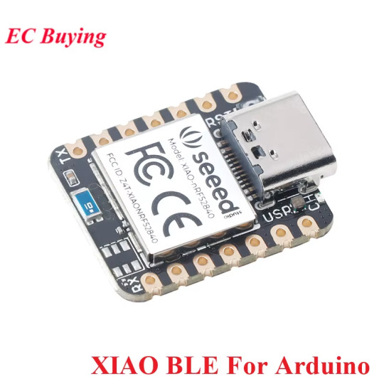
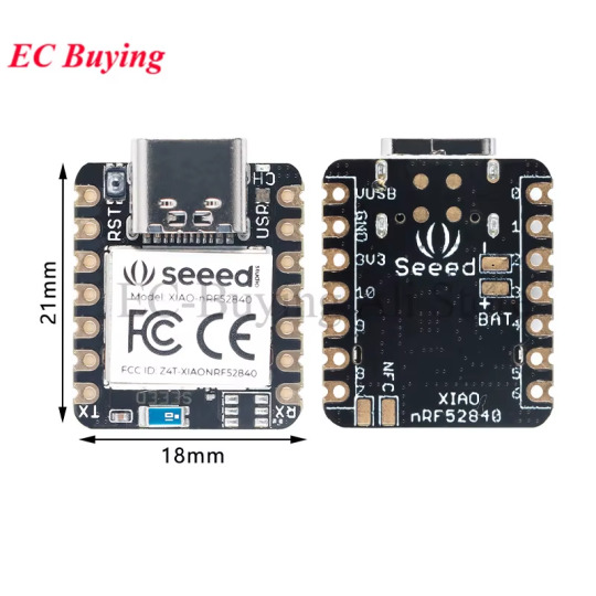
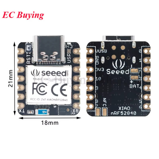
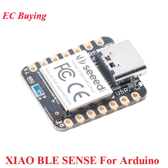
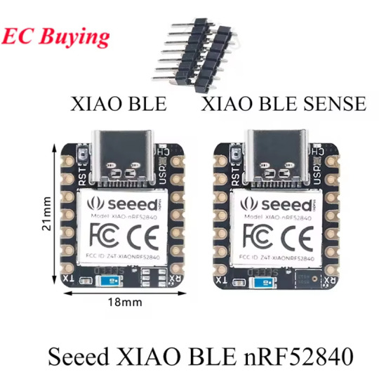
Ideal for IoT, Wearables & TinyML Projects Seeeduino XIAO BLE SENSE - Advanced IoT Microcontroller ⚡ Powerful ARM Cortex-M4 CPU with FPU @ 64 MHz 🌐 Bluetooth 5.0, NFC, Zigbee for wireless connectivity 🔋 Ultra-low sleep power: 5 μA deep sleep mode 🔋 BQ25101 chip for lithium battery charge management Price Now: USD 5.02 (Original price: USD 6.70, 25% off) 🔗Click & Buy:
#SeeeduinoXIAO#BLEsense#ArduinoFun#RP2040#nRF52840#BluetoothMagic#MicrocontrollerLife#TechTinkering#GadgetGoals#MakerMovement#DIYProjects#ElectronicsEnthusiast#CodingAdventures#TechieTuesdays#InnovateWithUs#SmartTech#ArduinoCommunity#SeeedStudio#GeekyGear#TechSavvy#CircuitBoardLove#CreativeCoding#BuildAndLearn#HandsOnTech#FutureOfMaking#NerdyByNature#GizmoGuru#RoboticsFun#TechieVibes#ExploreElectronics
0 notes
Text
Mikrocontroller ESP32C3 von Seeed Studio
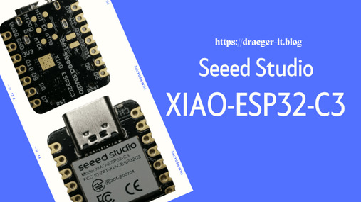
In diesem Beitrag möchte ich dir den Mikrocontroller ESP32C3 von der Firma Seeed Studio vorstellen.

Dieser Mikrocontroller trägt durch seine geringen Abmaße mal wirklich zurecht die Bezeichnung "Mikrocontroller".

ESP32-C3 von Seeed Studio

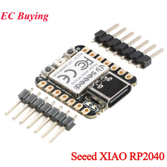
ESP32-C3 von Seeed Studio (Rückseite) Von der Firma Seeed Studio habe ich dir bereits den Seeed Studio XIAO RP2040 – ein Zwerg mit großer Leistung vorgestellt, welcher die gleichen Abmaße hat, wie der hier gezeigte ESP32C3.

Vergleich XIAO RP2040 mit ESP32-C3 von Seeed Studio
Bezug des ESP32C3 von Seeed Studio
Den mir vorliegenden Mikrocontroller habe ich auf berrybase.de für 8,45 € zzgl. Versandkosten erstanden. ShopPreisVersandkostenhttps://www.berrybase.de8,45 €3,95 €https://botland.de7,90 €4,95 €https://eckstein-shop.de7,95 €1,99 € Lieferumfang Der Mikrocontroller wird zusammen mit einer externen Antenne in einer kleinen Plastiktüte geliefert.

Mikrocontroller ESP32-C3 verpackt

ESP32-C3 von Seeed Studio mit externer Antenne Damit du diesen also auf ein Breadboard stecken möchtest, benötigst somit noch zusätzlich zwei 7-Pin Stiftleisten im 2,54 mm Rasterformat. Diese Stiftleisten bekommst du auf ebay.de bereits ab knapp 3 € für ein ganzes Pack mit 5 Leisten mit je 20 Pins.
Technische Daten des ESP32C3
Nachfolgend zunächst die technischen Daten des ESP32C3. ProzessorESP32-C3, 32bit, RISC-VTaktgeschwindigkeit160 MHzSpeicher400 KB SRAM, 4 MB FlashSchnittstellenI²C, UART, SPI, I²Sdrahtlose SchnittstellenWiFi, Bluetooth Low Energy 5 (BLE)Pins11 digitale PWM Pins, 4 analoge PinsFeaturesReset-Button, Boot-Button, Lötaugen für JTAG & Batterie Einen Vergleich mit den anderen Mikrocontrollern sowie weitere Informationen findest du auf der englischen Seite Getting Started with Seeed Studio XIAO ESP32C3.
Pinout des ESP32C3
Der Mikrocontroller hat nachfolgendes Pinout.

Pinout des Mikrocontrollers ESP32-C3
Stiftleisten anlöten
Wie erwähnt liegen dem Mikrocontroller keine Stiftleisten bei, jedoch werden diese benötigt um diesen mit Sensoren & Aktoren per Breadboardkabel oder einem XIAO Grove Base zu verbinden. Ich empfehle dir den Mikrocontroller auf ein Breadboard zu stecken, denn so kannst du die Stiftleisten in einem vernünftigen 90° Winkel anlöten.


XIAO Grove Base Shield
Wenn wir die Stiftleisten angelötet haben, dann können wir den Mikrocontroller auf das XIAO Grove Base Shield stecken und haben somit nicht nur die Möglichkeit Sensoren/Aktoren per Breadboardkabel zu verbinden, sondern auch per Grove Adapter.


Auch hier habe ich noch zusätzlich die Stiftleisten angelötet und kann somit parallel Breadboardkabel und Grove Adapter anschließen.
Einrichten und Programmieren des ESP32-C3 in der Arduino IDE 2.0
Im nachfolgenden YouTube-Video erläutere ich dir, wie du den Mikrocontroller in der Arduino IDE 2.0 einrichtest und ein erstes kleines Programm schreibst. https://youtu.be/yu5lj6qLxVk
Programmieren in der Arduino IDE
Gem. Hersteller Seeed Studio kann dieser Mikrocontroller in der Arduino IDE programmiert werden. Dazu musst du jedoch zunächst den Boardtreiber installieren. Zunächst musst du jedoch die Adresse zu dem benötigten Boardtreiber in den Einstellungen der Arduino IDE hinzufügen. https://raw.githubusercontent.com/espressif/arduino-esp32/gh-pages/package_esp32_index.json Der Mikrocontroller wird unter Tools > Port als "Adafruit QT Py ESP32-C3" erkannt.

Wenn wir den Port gewählt haben, wählen wir noch aus der Liste der Mikrocontroller von Tools > Board: xyz > esp32 > XIAO_ESP32C3 aus.

LED blinken am ESP32-C3 von Seeed Studio
Zunächst ein kleines Beispiel mit einer LED am ESP32.

Mikrocontroller ESP32-C3 mit Grove LED Hier nun der Code um eine LED welche am GPIO8 angeschlossen ist im Intervall von 250 Millisekunden blinken zu lassen. //LED am GPIO8 angeschlossen #define led 8 void setup() { //definieren das der Pin //der LED als Ausgang dient pinMode(led, OUTPUT); } void loop() { //aktivieren der LED digitalWrite(led, HIGH); //eine kleine Pause von 250 ms. delay(250); //deaktivieren der LED digitalWrite(led, LOW); //eine kleine Pause von 250 ms. delay(250); } Read the full article
1 note
·
View note
Text
ML_SynthTools ~ Arduino Synthesizer Library
This library is made to be used for synthesizer projects. It contains modules to create sound, to drive an audio codec and create some audio effects. This library supports different platforms: ESP32, ESP32S2, ESP32S3 ESP8266 Seeedstudio XIAO (samd21 – cortex-m0plus) Teensy 4.1 (imxrt1062) Daisy Seed (cortex-m7) Raspberry Pi Pico (rp2040) STM32F407…
View On WordPress
0 notes
Text
Raspberry Pi, MQTT and RealVNC
When I got Sensecap S2103 LoRaWAN® CO2, Temperature, and Humidity Sensor, I was thinking to integrate it with commercial Scada HMI system. One of the reasons is because Sensecap S2103 is a set of sensors which are applicable in industrial applications. Later, an idea came to me why not to use Raspberry PI with screen - Human Machine Interface together with RealVNC to make Industrial – grade reusable application.
The best thing in this project Remote Access for your Raspberry Pi from Anywhere in the world via VNC connection, meaning you have Scada HMI system anywhere, on any device.
In this post I am going to show how to integrate Sensecap S2103 sensor and display collected data on Raspberry Pi display.
Since picture is worth a thousand words, block schematics below shows architecture of my project.

I will show data from SenseCap S2103 sensor on Home Assistant which is installed on reTerminal . I will not go step-by-step on configuration/installation of Home Assistant on reTerminal, but you can see great guide on seeedstudio wiki here https://wiki.seeedstudio.com/reTerminal_Home_Assistant/.
I used the guides from link above and Home Assistant Supervised installation/configuration method in order to have data displayed on reTerminal LCD.
Home Assistant acts as a central smart home controller hub by combining different devices and services in a single place and integrating them as entities. That means you can integrate various sensors and variouts services in one single place.
Process of installing Home Assistant Supervised on reTerminal is like following:
I am assuming that you already have installed Raspberry PI OS.
Install RealVNC https://www.realvnc.com/en/
Install docker
Visit Home Assistant OS Agent page, and install Home Assistant Agent V1.3.0. and also Home Assistant-Supervised
Install Portainer Docker management platform
On portainer dashboard make sure that Home Assistant primary containers are up and running
On a web browser, type the following URL homeassistant.local:8123
If everything is installed without problems, you can view Home Assistant Dashboard UI on your web browser and proceed with making your account
RealVNC server should come preinstalled no your SD card with Raspbian OS. If, for any reason this is not case with you, below are informations on how to Install the RealVNC for Raspberry pi.
How to Install the RealVNC on Raspberry Pi
Update the system repositories:
Open the terminal if you have direct access. Or, take an SSH session to the Raspberry Pi CLI. $ sudo apt-get update && apt-get upgrade
2. Install the RealVNC server:
$ sudo apt-get install realvnc-vnc-server.
3. Enable VNC server:
$ sudo raspi-config Got to Interfacing options Select VNC Answer Yes Select Finish to quit (or ESC)
Note: VNC runs on port 5900. You should open this port on all the middle devices to work the communication from your PC to the Raspberry Pi.
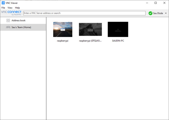
On PC side, you must install RealVNC Viewer, in ordes to access HMI remotely. Below is how RealVNC viewer loooks after installation.
First big part of the project is finished. Now we are going to configure SenseCAP sensor by using Sensecap MATE Android application. Again, amazing guideline can be followed on Seed's wiki: https://wiki.seeedstudio.com/Cloud_Chain/SenseCAP_Mate_APP/SenseCAP_APP/
The next step is to configure mqtt integration with Home Assistant and subscribe to SenseCAP data.
First, what you need to know is SenseCAP account API ID, Organization ID, and Access API keys. Nice quickstart can be found on sensecap page.
https://sensecap-docs.seeed.cc/data_openstream_quickstart.html
Got to https://sensecap.seeed.cc/portal/#/security, in order to create Access Key and view information about Organization ID.

By clicking on API ID, you can also see API keys information.
So, your important connectivity informations for Home Assistant, which will be important in order to connect to MQTT, are as below:
Host: sensecap-openstream.seeed.cc
User: org-<OrgID> (here you replace OrgID with your Organization id-example for this parameter will be org-428131654987987)
Password: here you insert your Acces Key which is in form XBA6E65464 (a combination of letters and numbers).
Client ID: org-<OrgID>-quickstart (example: org-428131654987987-quickstart)
After this, go to https://www.home-assistant.io/integrations/, which allows integration with a lot of services. You will need, of course MQTT. Enter MQTT in search box, and choose MQTT, as shown below:
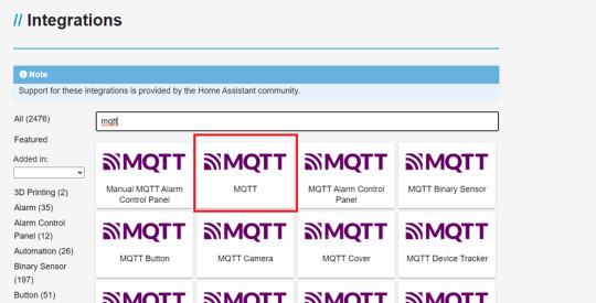
In Home Assistant now go to Settings->Devices & Services, Click add integration button and search MQTT. Now you enter the informations from above for MQTT connectivity:
Username= OrgID, password= client ID

Now, in order to test that MQTT connectivity works, click the CONFIGURE button and listen to the topic : device_sensor_data/OrgID/+/+/+/+
(example: device_sensor_data/428131654987987/+/+/+/+).
After few seconds, you will have response: vaule and timestamp in JSON format.
Since we want to show values of temperature, CO2 and humidity, we need to add multiple entities to store aquired sensor data, by editing the Home Assistant configuration file.
Go to the settings, click to Add-ons,search for File Editor, modify the YAML file /config/configuration.yaml by entering:
mqtt:
sensor:
- name: "Air Temperature"
state_topic: "/device_sensor_data/<orgID>/<DeviceEUI>/1/+/4097"
unit_of_measurement: "℃"
value_template: "{{ value_json.value }}"
- name: "Air Humidity"
state_topic: "/device_sensor_data/<orgID>/<DeviceEUI>/1/+/4098"
unit_of_measurement: "%RH"
value_template: "{{ value_json.value }}"
- name: "Air CO2"
state_topic: "/device_sensor_data/<orgID>/<DeviceEUI>/1/+/4100"
unit_of_measurement: "ppm"
value_template: "{{ value_json.value }}"
DeviceEUI is Unique identification of device eg. 2CF7F12000000001, and it can be found on the sensor itself.
Now the last step is create dashboard.
go to overview and find the "Edit Dashboard"
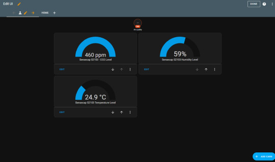
You can add cards as much as you want. I have added Gauge card, and subscribed to entities (temperature, CO2 and humidity).
Finally, the IoT dashboard is shown on your reTerminal Home assistant main screen.
Here below are few pictures for you to see how it looks like:


0 notes
Text
#AzureIoT – Using a Raspberry Pi @Seeedstudio Grove Sensors 👀 in an ☁ Azure IoT Edge Module
#AzureIoT – Using a Raspberry Pi @Seeedstudio Grove Sensors 👀 in an ☁ Azure IoT Edge Module
Hi ! Last week during my sessions for #JulyOT, I had several questions about how to use SeeedStudio Grove sensors and actuators in custom Azure IoT Edge modules. I’m updating my previous series of posts to how how to access to specifics sensors connected to the device and send telemetry, and more. I’m missing the Digital Twin part, however, I will wait some time to publish that series. It all…

View On WordPress
0 notes
Photo

Working with this cute board @seeedstudio XIAO is the smallest Arduino compatible board in Seeeduino Family. It is an Arduino microcontroller that is embedded with the SAMD21 microchip. #xiao #seeedstudio #seeeduinoxiao #arduino #microcontroller #programming #ide #electronics #developmentboard #embedded #programmerlife #techvideo https://www.instagram.com/p/CfGCY4iLcoV/?igshid=NGJjMDIxMWI=
#xiao#seeedstudio#seeeduinoxiao#arduino#microcontroller#programming#ide#electronics#developmentboard#embedded#programmerlife#techvideo
0 notes
Text
4 PCB prototyping services
흥미로운 질문을 발견했다.
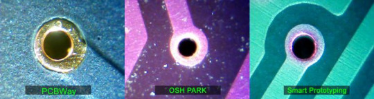
PCBWay vs OSH Park vs Smart Prototyping
from http://electronics-lab.com/community/index.php?/topic/41373-pcbway-vs-osh-park-vs-smart-prototyping/
해당 링크에 방문해서 보면 아래처럼 직접 생산해보고 비교한 그림을 올려 뒀으니 참고하시고,

무튼 회로도는 설계를 했는데, PCB 프로토타입을 어디에서 생산하느냐?
아니면, 회로도에서 PCB 조립까지 해 주는 곳이 없나?
이런 고민이 있는 경우, 아래 서비스들을 살펴보면 되겠다. 먼저, 내가 알고 있는 서비스는
1. OSH Park (https://oshpark.com/)
made in the U.S 눈에 띄네!!
그래서인지, tindie.com 에 보면 많은 maker 들이 이 서비스를 이용해 bare PCB를 판매하고 있���.

아까 찾은 질문에 보면 관련된 업체가 더 많은 것을 알 수 있다.
2. PCBWay (https://www.pcbway.com/)

3. Smart Prototyping (https://www.smart-prototyping.com/)

그리고, 아주 유명한 업체 하나더~
4. Seeed Studio (https://www.seeedstudio.com/fusion.html)
7일 이내로 생산 조립(?) 까지 가능하다고 얘기하는 거냐 ^^
머 나름 중국업체지만 믿을만한 브랜드 이미지를 가지고 있다. 최소한 나한테는~

0 notes
Text

It's happening! Starting to see more and more folks IN PERSON! Eric from seeedstudio stopped by Adafruit - will be doing some colabs maybe together! check out seeed ! https://www.seeedstudio.com/
8 notes
·
View notes
Text
While browsing in a thrift store some months ago, I found a selection of stepper motors. I picked up some matching NEMA 17 motors, the size you find in 3d printers, but also two NEMA 08s.

The 08 refers to the size. NEMA specifies the size numbers as the size of the faceplate (around the motor's shaft), measured in tenths of an inch. So a NEMA 08 motor's face is 0.8" across — nicely compact, and I plan to make a little pen plotter with these.
The trouble starts when you try to make them run. These aren't "hobby motors", where if you stick one wire on either end of a battery, it runs. Stepper motors have, at minimum, four wires, so that's not going to work. You can look at a good description of how they work on Wikipedia, but suffice it to say that the easiest way to get real control on these is to use a microcontroller and a motor driver board. The microcontroller is a tiny computer that tells the motor driver how and when to move the motor, and the driver translates that into the proper voltages on the right wires.
Fortunately, I have both of these. For a microcontroller, I have an Arduino — just an old one I had lying around, which is plenty — and for a motor driver, I have a Seeedstudio Motor Shield, which plugs into the Arduino and provides places to connect the stepper motor and the power to drive it (I got these at Radio Shack, which may indicate just how long I've had them). Unfortunately, a Motor Shield can only drive a single stepper, and I want to drive both of them. I could buy a driver board to run both motors, but I don't really want to spend extra money right now. I do have a second Motor Shield, so the quickest thing would be to use two Arduinos, put a Motor Shield on each one, and have the two microcontrollers coordinate somehow. But that's much more complicated than running both motors off one micro.

What I arrived at is the above. A Motor Shield uses pins 8, 11, 12, and 13 to drive the motor. But each Motor Shield also has what Seeed calls Grove connectors along the side, which let you get to the pins on the Arduino that the shield isn't using. So I've wired some of those to the operative pins on the second shield. So when the standard setup to use a Motor Shield goes like:
StepperMotor myStepper(stepsInARevolution, 8, 11, 12, 13);
I can turn around and say:
StepperMotor myStepper1(stepsInARevolution, 8, 11, 12, 13);
StepperMotor myStepper2(stepsInARevolution, 2, 3, 4, 5);
and behave as though I had a shield that could run both at once.
4 notes
·
View notes
Text
Looking to Safely Overclock Raspberry PI 4 to max 2.17ghz
Over clocking that Raspberry PI 4 is a must and if done wrong can lead into buying a new one. Nobody wants that for sure. Lol Well looking into the best way to overclock a pi 4 I ran across this article below on seeedstudio written by Shaun With the default at 1.5GHz Shaun goes over the exact script that needs to be in place to overclock it all the way up 2.14GHz if you want. I decided to keep…

View On WordPress
1 note
·
View note
Text
Nouvelle carte de développement SeeedStudio Sipeed Maixduino format Arduino+ESP32 avec unité traitement AI vision+audio
Nouvelle carte de développement @seeedstudio Sipeed Maixduino au format #Arduino intégrant un #ESP32 et une unité traitement AI pour la vision et audio
La nouvelle carte de développement Sipeed Maixduino du fabricant chinois SeeedStudio vient compléter la nouvelle gamme MAIX AIpermettant de réaliser des traitements à base d’intelligence artificielle directement au niveau de l’objet connecté sans avoir recours à des ressources déportés tel qu’un cloud. La Sipeeed Maixduino est une carte de développement au format Arduino Uno ce qui permettra de…
View On WordPress
0 notes
Text
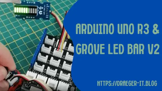
Arduino UNO R3 & Grove LED Bar v2

In diesem Beitrag möchte ich dir die Grove LED Bar v2 vorstellen und zeigen, wie diese am Arduino UNO R3 programmiert wird.
Wie du eine LED Balkenanzeige am Arduino programmieren kannst habe ich dir bereits in zwei Beiträgen gezeigt, dieses Modul hier ist jedoch etwas spezieller und daher widme ich es einen speziellen Beitrag.
Welche Projekte sind mit einer Grove LED Bar am Arduino UNO R3 möglich?
Das mir vorliegende Model hat eine rote, gelbe, hellgrüne sowie sieben grüne LEDs, an diesen können wir nun Sensordaten (Temperatur, Luftdruck etc.) visualisieren oder auch die Lautstärke über einen Geräuschdetektor. In den nachfolgenden Abschnitten werde ich dir die kleinen Projekte beschreiben und aufzeigen, wie diese in der Arduino IDE 2.0 programmiert werden.
Benötigte Ressourcen für die Projekte mit der Grove LED Bar am Arduino UNO R3
Wenn du die nachfolgenden Projekte nachbauen möchtest, dann benötigst du: - einen Arduino UNO R3, - ein USB-Datenkabel, - ein Grove Base Shield, - eine Grove LED Bar v2, - einen Grove Drehpotentiometer, - ein Grove Water Level Sensor
Aufbau der Grove LED Bar v2
Auf der Vorderseite des Moduls findest du die LED Balkenanzeige und auf der Rückseite die Grove Schnittstelle mit den Pinbeschriftungen. Zusätzlich hast du noch oben und unten Lötaugen für Stiftleisten im Rastermaß 2,54 mm.
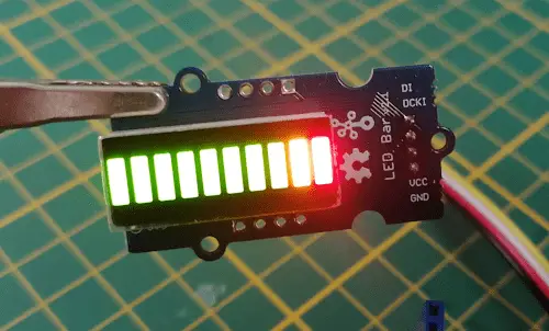
Technische Daten Betriebsspannung3.3V / 5VUmgebungstemperatur-20 °C bis +80 °CLEDs10 StückAbmaße (L x B x H)40 mm x 20 mm x 17 mm Wie erwähnt sind 10 LEDs auf dem LED Bard Modul verbaut, diese LEDs haben nachfolgende Daten: LEDWellenlängeLichtintensitätRot630 - 637 nm50 - 70 mcdGelb585 - 592 nm45 - 60 mcdGelb-grün570 - 573 nm28 - 35 mcd Dieses ist lediglich ein Auszug aus den technischen Daten, welche du auf der offiziellen Seite von Seeed Studio zu diesem Modul findest.
Bibliothek für den Chip MY9221 auf der Grove LED Bar
Damit du dieses Modul in der Arduino IDE programmieren kannst, benötigst du eine Bibliothek. Von der Firma Seeed Studio bekommst du neben einer kleinen Wiki-Seite zu diesem Bauteil auch ebenso eine Bibliothek nebst Beispielen. Um diese Bibliothek zu finden und zu installieren, musst du lediglich nach MY9221 im Bibliotheksmanager suchen und die Schaltfläche "INSTALL" betätigen.

Bibliothek für Grove LED Bar v2 von Seeed Studio
Programmieren in der Arduino IDE 2.0
Wenn die Bibliothek installiert wurde, dann können wir mit der Programmierung starten. Steuern der LEDs per Drehpotentiometer Für den Aufbau benötigst du zusätzlich noch einen Grove Drehpotentiometer, welcher am analogen Pin A0 angeschlossen wird. #include //der Drehpotentiometer ist am //analogen Pin A0 angeschlossen #define rotaryResistor A0 // CLK Pin = 7, // DATA Pin = 6, // Orientation = 0 // Typ = LED_BAR_10 Grove_LED_Bar bar(7, 6, 0, LED_BAR_10); void setup() { //beginn der Kommunikation mit der LED Bar bar.begin(); //Wenn wir unseren Drehpotentiometer drehen //soll von grün nach rot navigiert werden bar.setGreenToRed(true); } void loop() { //auslesen des Wertes vom analogen Pin int value = analogRead(rotaryResistor); //mappen des Wertes auf den Gültigkeitsbereich der LED Bar float level = map(value, 0, 1020, 0, 10.1); //setzen des ermittelten Wertes bar.setLevel(level); //ein kleine Pause von 25 Millisekunden delay(25); } Wenn du das kleine Programm auf den Arduino UNO gespielt hast und den Drehpotentiometer drehst, dann wird je nach Stellung ein Level an der LED Balkenanzeige gesetzt.
Grove Water Level Sensor & LED Bar v2
Mit dem Grove Water Level Sensor können wir den Füllstand eines Gefäßes prüfen. Natürlich müssen wir aufpassen, dass wir die offene Elektronik nicht mit Wasser benetzen, aber das Ganze ist natürlich erstmal sehr experimentell und daher in einem geschützten Bereich. Für den Aufbau benötigen wir jetzt zusätzlich noch ein kleines Gefäß und etwas Wasser.
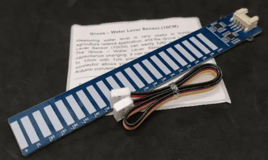
Die offizielle Dokumentation zum Grove Water Level Sensor findest du auf der Wiki-Seite von Seeed Studio. Auf der Seite findest du auch zusätzlich noch ein Beispiel, wie du dieses per I2C programmierst. Ich habe den Code in eine Bibliothek umgewandelt und stelle dir diese auf meinem GitHub Repository StefanDraeger / Grove-Water-Level-Sensor zum Download als ZIP-Datei bereit. Wie du eine Bibliothek in der Arduino IDE installierst, habe ich dir bereits im Beitrag Arduino IDE, Einbinden einer Bibliothek erläutert. #include #include // CLK Pin = 7, // DATA Pin = 6, // Orientation = 0 // Typ = LED_BAR_10 Grove_LED_Bar bar(7, 6, 0, LED_BAR_10); WaterLevelSensor sensor = WaterLevelSensor(); void setup() { //beginn der seriellen Kommunikation mit 9600 baud Serial.begin(9600); //beginn der Kommunikation mit der LED Bar bar.begin(); bar.setGreenToRed(true); } void loop() { //lesen des Grove Wasser Level Sensors int waterLevel = sensor.readPercentage(); //Ausgeben des ermittelten Wertes Serial.print(waterLevel); Serial.println("%"); //mappen des Wertes auf den Gültigkeitsbereich der LED Bar float level = map(waterLevel, 0, 100, 0, 10.1); //setzen des ermittelten Wertes bar.setLevel(level); //ein kleine Pause von 25 Millisekunden delay(25); } Wenn du den Code auf dem Arduino ausführst und das Gefäß nun langsam mit Wasser befüllst, dann steigt ebenso auch die LED Balkenanzeige. https://youtube.com/shorts/BZPkmXJ3B-4 Read the full article
0 notes
Text
【IoTchallenge】アルコールセンサ&Lチカ電子工作編 #100
ウェアラブルデバイスを一人メーカーで���ってみよう!
#IoT #電子工作 #Wearabledevice #アルコールセンサ #LED #Arduino #seeedstudio
ついにIoT関連投稿100回目になった妄想ダイスキOKstyleです。 (more…)
View On WordPress
0 notes
Text
Making of an ESP8266 Vibrator Development Board - traps and pitfalls
Making of an ESP8266 Vibrator Development Board - traps and pitfalls #sextech @SeeedFusion #maker #DIY #ESP8266

About a year ago I made a ESP8266 based design for a vibrator development board including IMU, motor driver and battery charging. The design was based on the Adafruit ESP Huzaah, but I used components of Seeedstudio Open Parts Library. This is a library of parts (IC, connector, resistors) which are stocked at Seeedstudio especially for their PCBA (printed circuit board assembly) service. PCBA is…
View On WordPress
#Design#development board#eagle#esp8266#Fusion#internet of things#PCBA#printed circuit board assembly#Seeedstudio#serial connection#wireless charging
0 notes
Text
Notes on Shenzhen
Considered as the place for hardware pilgrimage, Shenzhen is home to the Silicon Valley of Hardware. We finally made the trip end May 2017 and had a chance to experience the evolving city. Below are a few recaps for my future reference.
youtube
How We Got There and Around
We took the scenic route by flying to Hong Kong and then transiting to Shenzhen’s Shekou Ferry Terminal from HKIA. It’s a 40 minutes ride, similar to a ferry from Singapore to Batam! I guess the flexibility in terms of flight timings to and fro HK made it more appealing.
Our meetings for the first two days were scheduled tightly so we mostly got about through petrol or electric taxis on metered fares (quite affordable at around 10 yuan starting price and 2.40 yuan/km). The electric taxis (all by BYD) were cleaner and more comfortable in my opinion. Having not taken any other transports, I would not be able to comment much on the metro and buses (although they seem pretty okay too from the outside).
Establishing Phone Communications
From our recent experience, I would certainly go online the next time and get one of these 4G data SIM cards from CUniq for traveling in both Hong Kong and China. You can have it delivered to you before you travel over. Otherwise, you could try data roaming with your existing local bundle (which is something Singapore carriers offer) for a one-time fee.

Paradise for Crowdfunding Seekers?
We managed to network with a few design houses and manufacturers located in Shenzhen to support our upcoming Kickstarter campaign and future distribution. Having met with the ‘locals’ there, we had a better understanding of how business is currently conducted in China and how even that is transforming in the near future. The ‘Shanzai’ spirit that people associate with copycat products nowadays are starting to become more like turning high-end products more accessible to the public but are starting to have more or even better quality than the originals. It is also relatively easy for people to start new businesses by tapping on the abundance of ODMs/OEMs, with each company differentiating by making a few changes to a similar product. The key thing here is about distributing the product fast and generating revenue. Very pragmatic.
Met with local incubator - Leaguer-Star


Met with Seeedstudio

Met with NOA Labs

Met with Workshop

Huaqiangbei Shopping Spree
What are a few big boys to do when you’ve got a whole day in Huaqiangbei? SHOPPING!!! We spent our last full day in Shenzhen at SEG Electronics Market and Huaqiang Electronics World. The entire area is littered with shops but we were told that people are starting to move out and find cheaper rentals. I’ll end this post with pictures of the items which I bought.

10x Lightning and MicroUSB 2-in-1 connectors - 5 yuan
These are for a simple project that I have in mind.

1x Rubber Desk Mat - 40 yuan
No more worries of sweaty elbows.

1x Lightning Cable - 10 yuan

1x RGB mechanical keyboard - 149 yuan
The only qualm that I have is that the backslash is beside ‘Enter’ rather than above it. Guess I’ll be shopping for another TKL mechanical keyboard =P

1x REMAX Water Tap Filter - 119 yuan

1x Wireless Soundbar - 100 yuan
youtube
1x Mi 5000 mAh Powerbank - 75 yuan

#shenzhen#hardware#electronics#huaqiangbei#silicon valley#seeedstudio#noa-labs#meetworkshop#seg#dji#byd#workshop#leaguerstar
0 notes
Text
Circuitrocks: Arduino and Raspberry Pi Shop
Circuitrocks is one of the general distributors of opensource-hardware in the Philippines. We were founded in 2015, and located in Metro Manila, Philippines. We provide low-cost and high-quality products, on-time delivery, and the best customer support.The products we distribute are widely applied to computer electronics, automotive electronics, consumer electronics, industrial controllers, medical, and Online Distributors of Arduino Raspberry Pi DFRobot Adafruit and SeeedStudio.
0 notes