
Let's enjoy DIY using the raspberry pi , Edison/Intel, and Arduino. hnegi38 engineer tweeting on the RPi etc.
Don't wanna be here? Send us removal request.
Statistics
We looked inside some of the posts by hnegi38 and here's what we found interesting.
Average Info
Notes Per Post
9
Likes Per Post
5
Reblog Per Post
4
Reply Per Post
0
Time Between Posts
2 months
Number of Posts By Type
Photo
11
Video
4
Text
2
Last Seen Tumblr Blogs


Fun Fact
Tumblr was attacked by a cross-site scripting worm deployed by the Internet troll group GNAA on Dec 3, 2012.
Photo
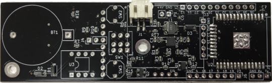
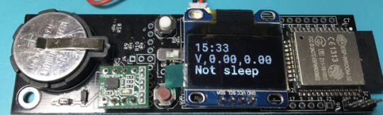
Li-ion battery based ESP32-WROOM-32 board
Li-ion x1 cell operation voltage is 2.8V ... 4.2V The power supply voltage of ESP32-WROOM-32 is 3.3V.
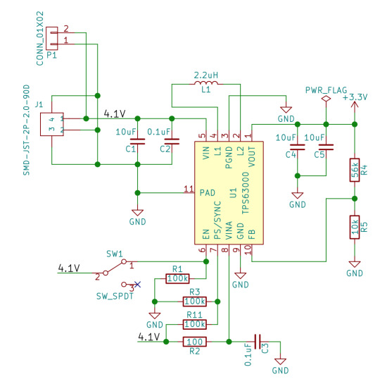
To get 3.3V efficiently, TI's Switching Regulator IC TPS63000DRCR, which can switch Step-Down / Step-Up automatically, is attractive.
However, this chip has narrow pins, making it difficult to solder even if a board is made. So, I tried the Fusion PCBA. I registered Gerber data on 5/30 and received boards on 6/15. Incredibly fast! The finish is also Good and I am satisfied!
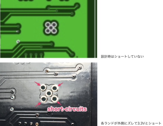
However, there was one point that was disappointing. The space between five lands was expanded by the Fusion side. This board was designed with L1 = GND and L2 = 3.3V, so L1 were short-circuited with the L2 by the four outer lands...
Fortunately, the short detection of TPS63000 has been successful.
As a countermeasure, insulation was obtained by scraping the land surface with a 3.5mm drill. :D
0 notes
Photo
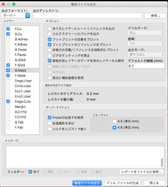
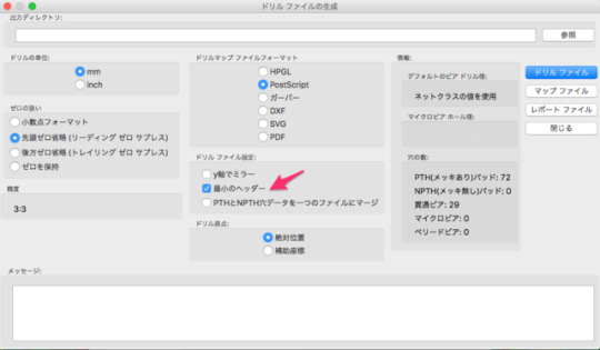
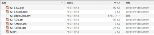
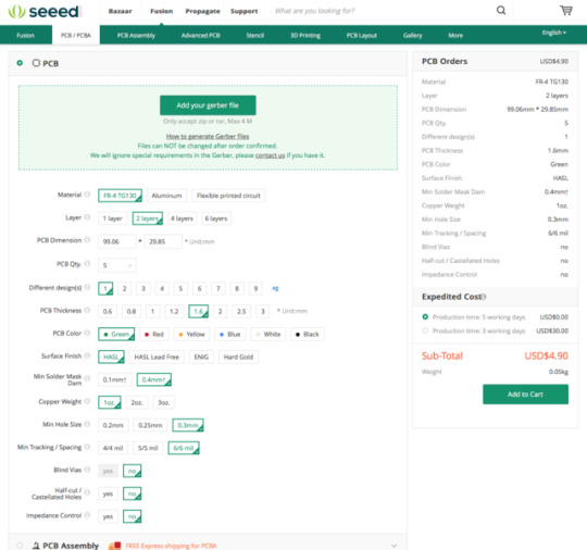
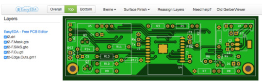

I made my PCB for first time by using KiCAD and ordered it to "Seeed Fusion PCB".
note ...
1. make 7 files (Gerber and Drill files), and zip 2. attach a zip file, and click "Add to Cart" button 3. you can see your PCB on the viewer of "Seeed" site beforehand
0 notes
Video
vimeo
LED will light when you approach.
Digispark ATTINY85 + HC-SR04
0 notes
Text
Digispark ATTINY85 + HC-SR04
LED will light when you approach.
Micro controler : Digispark ATTINY85 Ultrasonic Distance sensor: HC-SR04 1. setup ATTINY85 to your Arduino IDE http://digistump.com/wiki/digispark/tutorials/connecting 2. write your sketch 3. connect USB and upload the sketch, within 4 seconds
int interval = 0; double distance = 0; void setup() { pinMode( 1, OUTPUT); //LED on Model A or Pro pinMode( 0, OUTPUT ); //HC-04 trig pinMode( 2, INPUT ); //HC-04 echo } // the loop routine runs over and over again forever: void loop() { digitalWrite( 0, HIGH ); delayMicroseconds( 100 ); digitalWrite( 0, LOW ); // mesure the interval interval = pulseIn( 2, HIGH ); distance = interval * 0.017; // cm if ( distance < 20 ) { digitalWrite(1, HIGH); } else { digitalWrite(1, LOW); } delay(250); }
0 notes
Text
Remote PIR Motion Sensor
#include <SPI.h> #include <Wire.h> #include <Adafruit_GFX.h> #include <ESP_Adafruit_SSD1306.h> #define OLED_RESET 4 Adafruit_SSD1306 display(OLED_RESET); extern "C" { #include "user_interface.h" } #include <ESP8266WiFi.h> #include <ESP8266WebServer.h> #define WIFI_SSID "PUTYOURSSID" #define WIFI_PWD "PUTYOURPASSWD" ESP8266WebServer server(80); // HTML #define HTML_HEADER "<!doctype html>"\ "<html><head><meta charset=\"UTF-8\"/>"\ "<meta name=\"viewport\" content=\"width=device-width\"/>"\ "</head><body>" #define HTML_FOOTER "</body></html>" byte x=0; void setup() { // put your setup code here, to run once: pinMode(3, INPUT); //GPIO3=RxD pinMode(15, OUTPUT); //3V3B enable digitalWrite(15, HIGH); Wire.begin(4,5); //SDA,SCL = IO4,IO5 display.begin(SSD1306_SWITCHCAPVCC, 0x78>>1); // OLED ADDRESS display.clearDisplay(); display.setTextColor(WHITE); display.setTextSize(1); display.setCursor(0,0); display.println("\nWeb Server"); display.display(); WiFi.begin(WIFI_SSID, WIFI_PWD); // Wait until WiFi is connected while(WiFi.status() != WL_CONNECTED){ delay(1000); display.print("."); display.display(); } //display.println(""); display.clearDisplay(); display.setCursor(0,0); display.println("Connected!"); display.println("IP Address:"); display.println(WiFi.localIP()); display.display(); delay(3000); // Setup WebServer Handlers server.on("/", [](){ //String html = HTML_HEADER "<h1>NodeMCU!</h1>" HTML_FOOTER; String html = HTML_HEADER "<h1>PIR Motion Sensor: "; if ( x == 0) { html += "There is nobody."; } else { html += "There is somebody!"; } html += HTML_FOOTER; server.send(200, "text/html", html); }); server.begin(); } void loop() { // put your main code here, to run repeatedly: display.setTextSize(2); display.setCursor(0,40); display.setTextColor(BLACK); //clear the previous display display.println(x); display.setCursor(0,40); display.setTextColor(WHITE); //a = system_adc_read(); x = digitalRead(3); //result of PIR sensor display.println(x); display.display(); delay(1000); server.handleClient(); }
2 notes
·
View notes
Photo

programming to Wio Node as arduino (ESP-WROOM-02)
0 notes
Photo

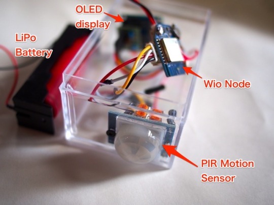
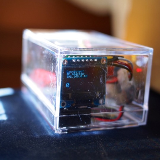


Is there somebody in the room?
You can see it from outside of the door by web-browser by putting this box in the room.
The PIR Motion Sensor DSUN can detect the existence of the homoiothermic animal. The DSUN's output pin is discriminated by the ESP-WROOM-02 that was programmed as web-server. So You can watch it from a separated place.
PIR Motion Sensor D-SUN PIR http://www.aitendo.com/product/10254
Wio Node (ESP-WROOM-02) http://wiki.seeed.cc/Wio_Node/
Grobe 4P Conversion Cable https://www.seeedstudio.com/Grove-4-pin-Female-Jumper-to-Grove-4-pin-Conversion-Cable-(5-PCs-per-PAck)-p-1020.html
0.96-inch OLED display I2C https://www.amazon.co.jp/product-reviews/B01MECPQ05/ref=cm_cr_dp_see_all_btm?ie=UTF8&reviewerType=all_reviews&showViewpoints=1&sortBy=recent
LiPo Battery18650 single cell
Battery Holder for LiPo
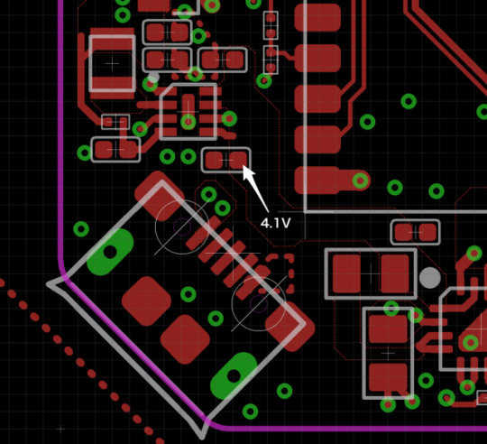
The DSUN's Vcc need 3.6V to 20V. The output voltage is 0V to 3.3V. Wio Node’s VSYS voltage was 4.1V when I measured. So, I used VSYS as Vcc of the DSUN.
0 notes

Video
vimeo
Weight sensor
#include "HX711.h" #include <SPI.h> #include <Wire.h> #include <Adafruit_GFX.h> #include <ESP_Adafruit_SSD1306.h> #define OLED_RESET 4 Adafruit_SSD1306 display(OLED_RESET); extern "C" { #include "user_interface.h" } byte x=0; HX711 scale(14, 12);//data, clk void setup() { // put your setup code here, to run once: pinMode(13, OUTPUT); //LED Wire.begin(4,5); //SDA,SCL = IO4,IO5 display.begin(SSD1306_SWITCHCAPVCC, 0x78>>1); // OLED ADDRESS display.clearDisplay(); display.setTextSize(2); display.setTextColor(WHITE); display.setCursor(0,0); display.println("Calibrating..."); display.display(); //scale.set_scale(); //for 1st scale testing scale.set_scale(952.8f); delay(400); scale.tare(20); delay(400); scale.tare(20); delay(400); scale.tare(20); display.clearDisplay(); display.setCursor(30,40); display.println("Done."); display.display(); delay(400); } void loop() { // put your main code here, to run repeatedly: display.clearDisplay(); display.setCursor(30,10); display.println( scale.get_units(20) ); display.setCursor(80,30); display.println( "g" ); display.display(); digitalWrite(13, HIGH); delay(4); digitalWrite(13, LOW); //delay(500); }
0 notes
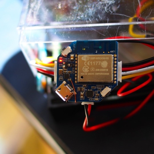
Photo
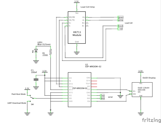

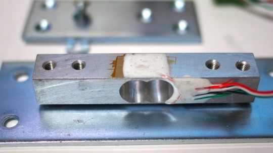

Weight Sensor
Load Cell (1kg) ---> HX711 (AMP) ---> ESP-WROOM-02 ---> 0.96inch OLED Display
Link http://barcelona.lomo.jp/wp/?p=23 https://github.com/bogde/HX711
2 notes
·
View notes
Video
vimeo
Upload a sketch to ESP-WROOM-02(ESP8266)
2 notes
·
View notes
Photo
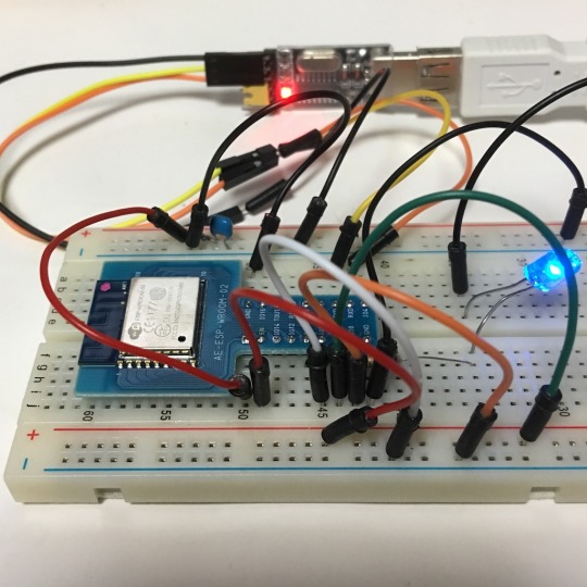
AT command of ESP-WROOM-02 (ESP8266) was working. Uploading a sketch was working, by Arduino IDE. But, after sketch uploading, AT command was not working. Arduino IDE was overwriting the firmware of AT command. So, I wrote the new AT firmware to WSP8266.
Download firmware writing tool: I use the terminal on MacOS Sierra. https://github.com/espressif/esptool $ cd esptool-master $ sudo python setup.py install
Test esptool.py: $ esptool.py --baud 115200 --port /dev/***usbserial*** read_mac esptool.py v1.3-dev Connecting... MAC: **:**:**:**:**:**
Download the AT firmware http://www.electrodragon.com/w/Category:ESP8266_Firmware_and_SDK $ esptool.py --baud 115200 --port /dev/***usbserial*** write_flash 0x00000 a.bin
Notice: ESP-WROOM-02 (ESP8266) need a bypath-condenser !
0 notes
Photo

3.5 inch TFT LCD 480x320 (SPI) with TouchPanel + RaspberryPi3
Amazon https://www.amazon.co.jp/gp/product/B01LXM8NL4/ref=od_aui_detailpages00?ie=UTF8&psc=1
SPI setting $ sudo raspi-config 7 Advanced Options - A6 SPI - “ON"
driver download $ wget https://www.sunfounder.com/wiki/images/7/73/LCD-show.tar.gz $ tar xvf LCD-show.tar.gz $ cd LCD-show/ /LCD-show $ ./LCD35-show
2 notes
·
View notes
Photo
Spirit Level = Arduino 101 Accelerometer + I2C OLED Display The Arduino 101 has 3-axis Accelerometer. Their results are displayed on I2C-OLED. The "u8glib library for Arduino" could not use, some compiler-error occurred. So I made this with https://www.mgo-tec.com/blog-entry-31.html as a reference. Thank you.
#include "CurieIMU.h" #include "CurieTime.h" #include "Wire.h" #define OLED_ADDR (0x3C) byte DotB1[8]={ B00000000, B00000000, B01111110, B11100111, B11000011, B11000011, B11100111, B01111110 }; int axRaw, ayRaw, azRaw; float ax, ay, az; void setup_i2c(){ byte i,j,k; Wire.beginTransmission(OLED_ADDR); Wire.write(0xAE); Wire.write(0xA4); Wire.write(0xA5); Wire.write(0x00); Wire.write(0x10); Wire.write(0x00); Wire.write(0x2E); Wire.write(0x21); Wire.write(0x00 | 0); Wire.write(B01111111); Wire.write(0x22); Wire.write(0x00); Wire.write(0x07); Wire.write(0xB0 | 0); Wire.write(0x81); Wire.write(0x7f); Wire.write(0xA6); Wire.write(0xC0); Wire.write(0x8d); Wire.write(0x14); Wire.write(0xAF); Wire.endTransmission(); //Clear Display for(i=0; i < 8; i++){ Wire.beginTransmission(OLED_ADDR); Wire.write(0x00); //set display start line Wire.write(0xB0 | i); Wire.write(0x21);//set column addres Wire.write(0x00 | 0);//start column addres Wire.write(B01111111);//stop column addres Wire.endTransmission(); for(j=0; j < 16; j++){ Wire.beginTransmission(OLED_ADDR); Wire.write(0x40); for(k=0; k < 8; k++){ Wire.write(0x00); } Wire.endTransmission(); } } } void Disp88(byte x, byte y) { byte k; Wire.beginTransmission(OLED_ADDR); Wire.write(0x00); Wire.write(0xB0 | y); Wire.write(0x21); Wire.write(0x00 | x); Wire.write(B01111111); Wire.endTransmission(); Wire.beginTransmission(OLED_ADDR); Wire.write(0x40); for(k=0; k < 8; k++){ Wire.write(DotB1[k]); } Wire.endTransmission(); } void Del88(byte x, byte y) { byte k; Wire.beginTransmission(OLED_ADDR); Wire.write(0x00); Wire.write(0xB0 | y); Wire.write(0x21); Wire.write(0x00 | x); Wire.write(B01111111); Wire.endTransmission(); Wire.beginTransmission(OLED_ADDR); Wire.write(0x40); for(k=0; k < 8; k++){ Wire.write(0); } Wire.endTransmission(); } void setup() { CurieIMU.begin(); CurieIMU.setAccelerometerRange(2); CurieIMU.initialize(); CurieIMU.autoCalibrateAccelerometerOffset(X_AXIS, 0); CurieIMU.autoCalibrateAccelerometerOffset(Y_AXIS, 0); CurieIMU.autoCalibrateAccelerometerOffset(Z_AXIS, 1); Wire.begin(); setup_i2c(); } void loop() { CurieIMU.readAccelerometer(axRaw, ayRaw, azRaw); ax = (axRaw * 2) / 32768.0; ay = (ayRaw * 2) / 32768.0; az = (azRaw * 2) / 32768.0; ax *= 80; ay *= -40; ax += 7; ay += 3; if (ax >= 15) { ax = 15; } else { if ( ax <= 0){ ax = 0; } } if (ay >= 7) { ay = 7; } else { if ( ay <= 0){ ay = 0; } } Disp88(ax*8, ay); delay(100);//100ms Del88(ax*8, ay); }
0 notes
Photo

1. IDEをDLする https://www.arduino.cc/en/Main/Software 1.6.9をJUST DOWNLOADする。 2. programming 初期化とループが最初から用意されているのでCで書く 左上のチェックマークでコンパイル 3. USBでつなぐ ツール:ボードArudiono/Genuino 101を選択 シリアルポート:/dev/cu.usbmodem1441(Arudiono/Genuino 101) を選択する。 チェックマークの横の右矢印でArduinoに書き込み
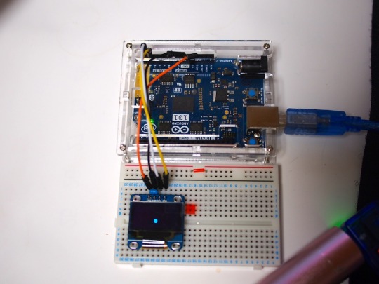
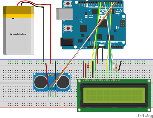
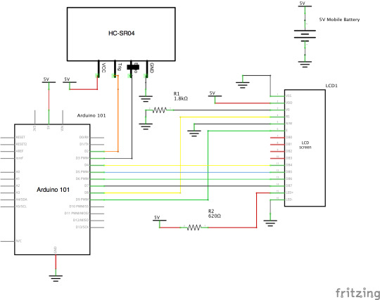
Digital measure : LCD 1602A + HC-SR04 + Arduino 101
LCD: 1602A
Supersonic distance sensor: HC-SR04
Arduino 101 (Intel CURIE)
------------------------------
#include <LiquidCrystal.h> LiquidCrystal lcd(8,9,4,5,6,7); int interval = 0; double distance = 0; int int_distance = 0; void setup() { pinMode( 2, OUTPUT ); //HC-04 trig pinMode( 3, INPUT ); //HC-04 echo lcd.begin(16,2); lcd.clear(); lcd.setCursor(0,0); lcd.write("Distance"); lcd.setCursor(0,1); lcd.write(" "); } void loop() { // pulse ! digitalWrite( 2, HIGH ); delayMicroseconds( 100 ); digitalWrite( 2, LOW ); // mesure the interval interval = pulseIn( 3, HIGH ); distance = interval * 0.017; // cm int_distance = round(distance); lcd.setCursor(0,1); lcd.print( int_distance ); lcd.write ( " cm "); delay(250); }
------------------------------
1 note
·
View note
Photo
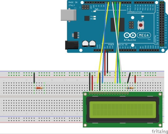

Try the 1602A LCD and the Arduino Mega2560
---
#include <LiquidCrystal.h> /* lcd(RS, E, DB4, DB5, DB6, DB7) */ LiquidCrystal lcd(8,9,4,5,6,7); void setup() { // put your setup code here, to run once: lcd.begin(16,2); lcd.clear(); lcd.setCursor(0,0); lcd.write("LCD Sample"); lcd.setCursor(0,1); lcd.write("Hello World!"); } void loop() { // put your main code here, to run repeatedly: for (int i=16; i > 0; i--){ lcd.setCursor(i-1,1); lcd.write("Hello World !!!!"); delay(500); } lcd.setCursor(0,1); lcd.write(" "); delay(1000); }
0 notes